1
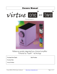
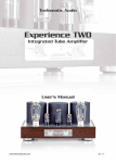
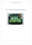
Modular Series
Line 2B SE Stereo Line Preamplifier
User’s Manual
Revised Nov 18/13
Mapletree Audio Design
Lloyd Peppard
R. R. 1, Seeley's Bay, Ontario, Canada, K0H 2N0
(613) 387-3830
www.mapletreeaudio.com
[email protected]
© Copyright Lloyd Peppard 2002-2013
Introduction
_
The Mapletree Audio Design Line 2B SE Stereo Line Preamplifier is part of the MAD
Modular Series of preamp/power supply components. It offers the audiophile a number of
desirable features:
? ? Compact chassis layout for use with separate power supply for low noise.
? ? Exclusive use of NOS 12SN7GT octal tubes, known for low distortion and
musicality.
? ? Heater voltage switch for use of 6SN7GT tubes if desired.
? ? Low output impedance (less than 500 Ohms).
? ? Parallel output jacks.
? ? User-specified gains of from 0 to 22 dB.
? ? Premium Auricap polypropylene film signal coupling capacitors.
? ? Alps volume control.
Power Supply Connections______
The Mapletree Line 2B SE consists of a preamplifier chassis with a separate power
supply. This allows separation between the two units and eliminates induced hum
originating from power supply circuitry and components. The Mapletree PS 2 or PS 2a
power supplies provide 12 VDC (regulated) at 0.6 A for the heater supply and +200 VDC
at full load (12 mA) for the B+ plate supply. The PS 2a has dual power outputs that allow
the Phono 3 phono preamp to share the power supply with the Line 2B. The power
connections to the preamplifier chassis are made through a special power cord that plugs
into jacks located on the rear panels of the power supply and preamplifier chassis. This
manual refers to the PS 2 power supply. Operation with the PS 2a is identical.
CAUTION: Do not operate the power supply when it is not connected to the
preamp. Damage of components may result.
Once the interconnecting power cord is securely attached between the two chassis and the
line cord is plugged in, the toggle switch on the front panel of the PS 2 is used to activate
the power supply. The pilot lamp indicates that the unit is on. It takes about 30 seconds
2
for the tubes to reach operating temperature ready for use. During operation, is it normal
for the power supply chassis to become warm to the touch.
The power supply is protected by a 1 A/250 V fast-acting fuse located inside the power
supply chassis. Under normal conditions, it should not be necessary to replace the fuse. If
power fails to come on, you can check the fuse and replace with a spare if necessary.
Wait 60 sec with the unit unplugged before removing the bottom cover. If the fuse blows
a second time, you should not try to operate the unit. Contact Mapletree Audio Design for
information regarding service.
Input/Output Connections______
The signal input/output jacks are located on the rear panel of the preamplifier chassis.
RCA jacks are provided for three stereo line inputs, and two stereo line outputs.
Depending on how you ordered your Line 2B SE, the line input gains may be different.
The standard configuration is 10 dB for all inputs. Consult the invoice included with your
shipment to verify the gains for your unit. The upper jacks are the left channel. The line
input impedance (resistance) is normally 100 k? , which provides minimal loading of any
line source such as CD/DVD player, tape deck, tuner, or PC sound card. If one or more
inputs have been configured for other than the 10 dB standard gain, the input impedance
will be affected. See the schematic diagram for details. The line output impedance is less
than 500 ? ? which is suitable for connection to a power amplifier through cables up to 10
ft in length.
The heater voltage switch located next to the power input jack allows you to
accommodate either 12SN7GT (supplied) or 6SN7GT tubes in your Line 2B. Note that
operation in the 12SN7 position with 6SN7 tubes installed will most certainly damage
the tubes.
1 Line
12SN7
2 Out 1
3 In 2
1 L R
6SN7
3
Preamp Controls____
The front panel controls of the preamplifier include a three-position source selector
switch to select between one of the three line inputs, balance control, and volume control
that acts on both channels.
Tubes____
The vacuum tubes supplied are new-old stock (NOS) and have been pre-tested. A burn-in
period of several hours may be needed to achieve the best sonic performance. Tube life
should be thousands of hours. Aging tubes may result in a reduced gain in one or both
channels or an increase in noise levels. Infrequently, a heater may burn out which is
indicated by total loss of sound. Replacement tubes can be obtained from several
suppliers in the U. S. and Canada. Mapletree Audio Design will attempt to provide
replacement tubes to customers at cost plus shipping. Some listeners enjoy trying
different brands and variants of tubes. The highly regarded 12SX7GT is equivalent to the
12SN7GT. The heater voltage switch permits the use of 6SN7GT tubes including the
5692 variant and currently manufactured types.
4
Parts List______
Part No.
C2a,b, C4a,b
Description
1.0uF/200 V polypropylene film capacitor
C3a,b
0.1uF/400 V pp film cap.
C5
D1a,b
J1a,b–J5a,b
J6
P1a,b
P2
R1a,b
R2a,b
R4a,b
R6a,b
R7a,b
R8a,b
R9a,b
R10
SW1
SW2
V1a,b
100uF/400 V electrolytic cap.
10 mA red LED
RCA gold plated phono jack
chassis jack (power in)
100K dual audio potentiometer (Alps)
100K linear potentiometer
100K 0.6 W 1% metal film resistor for 10 dB gain (see schematic)
511K 0.6 W 1% metal film res.
47.5K 0.6 W 1% metal film res.
511K 0.6 W 1% metal film res.
1K 0.6 W 1% metal film res.
10K 0.6 W 1% metal film res.
1M 0.5 W 1% metal film res.
5.1K 2 W metal oxide film res.
3 position, 2-pole rotary switch
DPDT toggle switch (heater voltage)
12SN7GT tube
5
Mapletree Audio Design
Line 2B SE Stereo Line Preamplifier
© Copyright Lloyd Peppard 2002-2013
Rev. Nov 4/13
Gain
1
1.8
3
4
5.6
8
10
dB
0
5
10
12
15
18
20
R1
340K
182K
100K
68K
47K
24.6K
22.1K
B
A
Input resistance ~ R1
+185 V
R2a
511 1%
+210 V
V1a
6/12SN7GT
R4a
47.5K 1%
J3a
3
J2a R1a-3
L. Line inputs 2
J1a R1a-2
1
+75 V
2
SW1a
Source
C2a
1.0/200
Auricap XO
1
R1a-1
R1a
100K 1%
C3a
0.1/400
Auricap XO
+49 V
4
P1a
Volume
100K
5
L. outputs
C4a
1.0/200
6
Auricap XO
+54 V
3
chassis
R6a
511K
1%
R1a replaces R1a-1,2,3 if
custom gains are not
required
D1a
10 mA red LED
J4a
J5a
R7a
1K 1%
R9a
1M
R8a
10K 1% 1%
P2
Balance
100K
V1b
6/12SN7GT
B
A
+185 V
3
R. Line inputs 2
1
J3b
+210 V
R4b
47.5K 1%
R2b
511K 1%
R1b-3
J2b R1b-2
+75 V
2
SW1b
Source
J1b
1
R1b-1
chassis
R1b
100K 1%
R1b replaces R1b-1,2,3 if
custom gains are not
required
C3b
0.1/400
C2b
1.0/200
P1b
100K
3
5
+49 V
4
R6b
511K
1%
R. outputs
6
+54 V
C4b
1.0/200
J4b
J5b
R7b
1K 1%
D1b
10 mA red LED
R9b
R8b
1M
10K 1% 1%
Ground bus
B
+185 V
A
+210 V
R10
5.1K 2W
C11
100/400
B-
+
_
12 VDC
+
12 V
7
7
8
8
A+ 4
3
A-
1
2 B+
J6
Power In
Rear View
6V
SW2
Heater Voltage
6/12SN7s
6
Circuit Operation______
Both channels are identical as shown in the schematic diagram. Operation will be
described for the left channel. The selector switch (SW1) selects from one of the three
line inputs (jacks J1–J3). Series resistors (R1) determine the gain of each line input. The
maximum gain, with zero resistance, is approximately 22 dB. The selected signal is
applied to the grid of the first section of the 12SN7GT which is configured as a commoncathode voltage amplifier with current feedback. The output from this stage is capacitor
coupled through C2 to the top of the volume control potentiometer P1. The signal at the
wiper of the level control is capacitor coupled through C3 to the grid of the output stage
comprising the second section of the 12SN7GT configured as a cathode-follower stage.
The grid bias voltage is established by R7 and the plate voltage by the sum of R7 and R8.
The operating conditions are chosen to provide the maximum possible output voltage
swing (around 13 V rms). The output voltage is taken from the cathode of this stage,
capacitor coupled to the output jacks J4 and J5 through capacitor C4. The gain of this
stage is less than unity but the output impedance is sufficiently low (less than 500? ) to
enable driving capacitive interconnect cables without high frequency loss.
Specifications______
Frequency response (100 k? ?50 pF load, 1 V output): 10 Hz–20 kHz –0.2 dB
Maximum input voltage: 5 V (rms)
Voltage Gain (100 k? load, 1 kHz): 10 dB (standard configuration)
Output impedance (1 kHz): 450?
Input impedance (1 kHz): 100 k? ?for 10 dB gain configuration
Hum and noise at output (max volume): less than 200 ? V rms
Phase: Inverting
Power consumption: 30 W
Warranty___
Assembled MAD components are warranted for 2 years to the original purchaser for
failure of parts (excluding tubes) and workmanship. Tubes are warranted for 90 days
exclusive of shipping cost. Service, including parts and labor (but excluding shipping), is
free within the warrantee period.
7
Mapletree Audio Design Preamplifier Power Supply PS 2
© Copyright Lloyd Peppard 2003-13
Rev. Nov 18/13
SW1
Power
FU1
1A/250V
1
L
G
J2
120 VAC 50-60 Hz
R1
6.8K 5W
3
5
115
VAC
V1
6X5GT
D3, D4
MUR180
TR1
2
115 VAC
25 mA
6
4
8
8
+
5
+
C1a
50/500
C1b
50/500
N
Chassis
4
330K 1W
115
VAC
115
VAC
1
2
3
7
3
Rear View
TR2
1
D1
1N4007
5
115
VAC
IC1
2
6
3
7
14 VAC
1.4 A
BR1
6A
3
+
4
TL780-12
12 V/1.5 A
1
R3
1.8K
+
2
C2
10000/25
115
VAC
D2
LED
8
1 2 3
TR3
5
6
4
8
6X5
2
7812
2
115
VAC
3
D1
7
6.3 VAC
0.9 A
IC1
1
115
VAC
Mounting tab
connected to pin 2
insulated from chassis
7
Power Supply Parts List ______
Reference No.
BR1
C1a,b
C2
D1
D2
D3, D4
FU1
J1
J2
IC1
R1
R2
R3
SW1
TR1
TR2
TR3
V1
J1
Power Out
Description
6A/200V diode bridge
Dual 50uF-50uF/500V electrolytic capacitor
10000uF/25V electrolytic capacitor
1N4007 diode
10 mA LED
MUR180 high speed diode (800 V)
1A/250V fast action fuse
3-pin chassis jack
IEC ac line receptacle
TL780-12 voltage regulator
6.8K 5W 5% wire-wound resistor
220K 1W 5% metal oxide resistor
1.8K 1W 5% carbon film resistor
SPST power switch (250 V rated)
230 VAC/25 mA power transformer
14 VAC/1.4 A filament transformer
6.3 VAC/0.9 A filament transformer
6X5GT rectifier tube
8