1
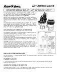
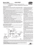
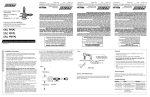
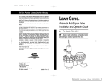
Connecting the Valve Wires (Figure 3)
Step 1- Route 18 AWG direct-burial sprinkler cable
from the timer to the valves.
Step 2- Using wire splice connectors, attach either
wire from each valve solenoid to the white cable
wire. This wire is designated as the valve “Common
Wire.” Connect the remaining wire from the solenoid to one of the color-coded wires.
Important: All wire splices must be insulated
with grease caps or similar waterproofing devices.
Step 3- At the timer, connect the control wires to
the numbered terminals in the desired operating
sequence and the valve common wire to the common terminal.
Step 4- Using the timer’s manual control feature,
test the operation of each valve.
Figure 3
Grease Cap
- Installation Guide -
Common
Wire
Figure 4
Flow Control
Screw
Manual Operation (Figure 4)
Bleed
• Bleed Screw (external bleed): To open the valve,
Screw
Bleed
turn the Bleed Screw counterclockwise one full turn
Handle
or until water begins discharging from the port.
Note: Removing the bleed screw is not required but
can be removed to help flush debris from the upper diaphragm area.
To close the valve, turn the bleed screw clockwise until it stops. Do not over-tighten!
• Bleed Handle (internal bleed): To open the valve, move the Bleed Handle counterclockwise to the stop. To close the valve, move the handle clockwise until resistance is
felt. Do not over-tighten!
• Flow Control Adjustment: With the valve operating, use a small screwdriver to turn
the flow control screw clockwise to decrease flow or counterclockwise to increase flow.
Note: The flow control screw requires approximately seven turns to adjust from maximum to minimum flow.
Caution: Do not use the flow control to shut off the valve. Do not force the flow
control screw past the end of normal adjustment travel. Damage can occur.
The Toro Promise — Limited One-Year Warranty
The Toro Company and its affiliate, Toro Warranty Company, pursuant to an agreement between them, jointly warrants, to the owner,
each new piece of equipment against defects in material and workmanship for the period of one year from the date of purchase.
Neither Toro nor Toro Warranty Company is liable for failure of products not manufactured by them even though such products may
be sold or used in conjunction with Toro products.
During such warranty period, we will repair or replace, at our option, any part found to be defective.
Return the defective part to the place of purchase.
Our liability is limited solely to the replacement or repair of defective parts. There are no other express warranties.
This warranty does not apply where equipment is used, or installation is performed, in any manner contrary to Toro’s specifications and
instructions, nor where equipment is altered or modified.
Neither Toro nor Toro Warranty Company is liable for indirect, incidental or consequential damages in connection with the use
of equipment, including but not limited to: vegetation loss, the cost of substitute equipment or services required during periods of
malfunction or resulting non-use, property damage or personal injury resulting from installer’s negligence.
Some states do not allow the exclusion or limitation of incidental or consequential damages, so the above limitation or exclusion may
not apply to you.
All implied warranties, including those of merchantability and fitness for use, are limited to the duration of this express warranty.
Some states do not allow limitations of how long an implied warranty lasts, so the above limitation may not apply to you.
This warranty gives you specific legal rights and you may have other rights which vary from state to state.
© 2007 The Toro Company, Irrigation Division
1" In-line Valve Models 53707 and 53709
Timer Connection
Form Number 373-0141 Rev. B
The Toro 1" in-line electric valves are designed for use in
an automatic sprinkler system controlled by a 24 V a.c.
sprinkler system timer. The valves feature manual flow
control adjustable down to zero flow and manual
bleed controls which enable the valve to be operated
without the use of the timer. The 53707 valve is
designed for slip-fit pipe connections and model
53709 features female-threaded inlet and outlet.
These valves are generally installed below grade,
grouped with other valves in a manifold arrangement and housed in a protective valve box.
53707
Important: These valves do not provide backflow protection.
53709
A backflow prevention device installed between the 1" in-line
valve(s) and the water source point of connection is required in most areas to prevent
back-siphoning of contaminants through the sprinkler system into the potable water
supply. The Toro 1" Pressure Vacuum Breaker (PVB), model number 53300, is
specifically designed for this purpose. Before connecting your irrigation system to the
potable water supply, consult with your local water utility department for information
regarding backflow prevention requirements. Where local water pressure exceeds 70
psi, a presure regulator should be used. (See Uniform Plumbing Code, Sec. 1007[b].)
It is advisable to use a regulator with any automatic valve to assure long life as well as
uniform and controllable operation.
Valve Specifications:
Operating Pressure: 20–150 PSI
Flow Range: 0.25–30 GPM
Solenoid:
24 V a.c., 60 Hz (nominal)
19 V a.c., 60 Hz (minimum)
Inrush: 0.40 amps, 9.6 VA @ 24 V a.c., 60 Hz
Holding: 0.20 amps, 4.8 VA @ 24 V a.c., 60 Hz
Friction Loss:
GPM Flow
PSI Loss
0.25 5
2.0 3.5
10
4.0
15
3.0
20
3.3
30
6.2
Installation Procedure
Note: To ensure ease of installation and optimum valve performance, please read
through the following instructions completely before starting the installation procedure.
Step 1- Route 1" schedule 40 PVC pipe from the backflow preventer or system
shut-off device to the valve location. Flush the supply line thoroughly!
Caution: Dirt, rocks and debris entering the valve can damage the valve and/or
cause the valve to malfunction.
Step 2- The instructions and illustrations on the next page provide the most commonly recommended methods of installing in-line valves in a manifold arrangement.
Use the appropriate step-by-step instruction for the valve model being installed.
• Model 53707 Installation (Figure 1)
Step 1- Cut a 4" length of 1" schedule 40 PVC pipe for each valve.
Step 2-Using PVC primer and cement, assemble the pipe section to the valve inlet
and tee fitting, aligning the tee perpendicular to the valve. Repeat this procedure for
each valve in the manifold.
Note: The last valve in the manifold can be connected with a 90° elbow instead of
a tee. However, if future expansion of the sprinkler system is expected, use the tee
fitting and a 4" section of 1" schedule 40 PVC pipe capped on the end. This enables
the main line to be easily connected to additional downstream valves.
Step 3- Using 4" sections of 1" schedule 40 PVC pipe, connect the valve assemblies
together to create the manifold, making sure the valves are aligned during assembly.
Step 4- Ensure the end of the supply line is dry and free of burrs. Cement the manifold to the main line.
Step 5- Allow the cemented connections to cure for a minimum of one hour (or
per the cement manufacturer’s directions) before applying water pressure. If no
leaks occur after pressurization, begin connecting the sprinkler zone piping using
1" class 200 PVC pipe.
Figure 1
Valve Inlet
1" Sch 40 PVC
4" Long
Valve Manifold Assembly
Cement
Joints
1" Slip x Slip x
Slip PVC Tee
• Model 53709 Installation (Figure 2)
1" Sch 40 PVC
4" Long
Step 1- Apply three complete wraps of PTFE tape to the slip/thread adapters.
Caution: Use only PTFE tape on threaded connections. Pipe dope and other
types of pipe thread sealants can damage plastic threads.
Step 2- Install a slip/thread adapter into each end of the valve and tighten securely.
Step 3- Cut a 4" length of 1" schedule 40 PVC pipe for each valve.
Step 4- Using PVC primer and cement, assemble the valve and PVC components as
shown, aligning the tee fitting perpendicular to the valve. Repeat this procedure for
each valve in the manifold.
Note: The last valve in the manifold can be connected with a 90° elbow instead of
a tee. However, if future expansion of the sprinkler system is expected, use the tee
fitting and a 4" section of 1" schedule 40 PVC pipe capped on the end. This enables
the main line to be easily connected to additional downstream valves.
Step 5- Using 4" sections of 1" schedule 40 PVC pipe, connect the valve assemblies
together to create the manifold, making sure the valves are aligned during assembly.
Step 6- Ensure the end of the supply line is dry and free of burrs. Cement the
manifold to the main line.
Step 7- Allow the cemented connections to cure for a minimum of one hour (or
per the cement manufacturer’s directions) before applying water pressure. If no
leaks occur after pressurization, begin connecting the sprinkler zone piping using
1" class 200 PVC pipe.
1" Class 200 PVC
Pipe To Sprinklers
1" Sch 40 PVC
Water Supply Pipe
Figure 2
90° Elbow or Tee and Cap Plug
Valve Inlet
1" Sch 40 PVC
4" Long
1" Slip x Thread Adapter
(PTFE-Taped threads)
Cement
Joints
1" Slip x Slip x
Slip PVC Tee
1" Sch 40 PVC 4" Long