1
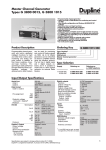
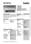
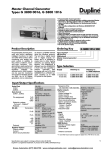
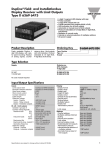
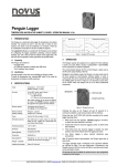
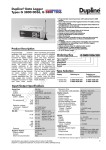
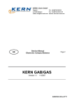
Du line
Monitoring Controller
Type G 3890 0034
®
Fieldbus
Installationbus
• Channel generator and logging unit
• Windows-based configuration software
• Up to 112 AnaLink signals
• Reading of analog and digital values via RS232
• Control of digital outputs via RS232
• Direct connection to printer through Centronics port
• Print-outs of continuous-, daily or history reports
• 48 loggins per point stored in EEPROM
• ISA alarm monitoring
• Alarm on-delay time configurable
• Built-in realtime clock and display
• 4 pushbuttons for manual operations
• AC or DC power supply
Product Description
Ordering Key
Generator controller 1 is designed for monitoring of analog signals, measured by 1channel AnaLink sensors. The
generator, once configured,
Type: Dupline®
Logging unit
Power supply
is able to monitor up to 112
analog signals and generate
various reports on a standard
IBM-graphics printer or compatible.
Type Selection
Supply
115/230 VAC
10 to 30 VDC
Input/Output Specifications
Ordering no.
Serial Port
Pin assignment
G 3890 0034 230
G 3890 0034 800
Supply Specifications
Power supply
AC-type
Rated operational voltage
through term. 21 & 24
jumper term. 22 & 23
jumper term. 21 & 23
and term. 24 & 22
Frequency
Rated operational power
Rated impulse withstand
voltage
115/230 V
Dielectric voltage
Supply - Dupline®
Supply - Output
Supply - Input
Supply - Com. ports
Power supply
DC-type
Rated operational voltage
through term. 21 & 22
Reverse polarity protection
Rated operational power
Inrush current
Rated impulse withstand
voltage
Dielectric voltage
Supply - Dupline®
Supply - Output
G 3890 0034 230
Overvoltage cat. III (IEC 60664)
Dielectric voltage
Com.port - Dupline®
Parallel Port
Pin assigment
230 VAC ± 15% (IEC 60038)
115 VAC ± 15% (IEC 60038)
45 to 65 Hz
Typ. 7 VA/3 W
4 kV
≥ 4 kVAC (rms)
≥ 4 kVAC (rms)
≥ 4 kVAC (rms)
≥ 4 kVAC (rms)
Overvoltage cat. III (IEC 60664)
10 - 30 VDC
Yes
7W
1A
800 V
500 V
200 V
T.D
R.D
GND
RTS
CTS
Strobe
Data D0-D7
Busy
Paper out
GND
Dielectric voltage
Com.port - Dupline®
Output
Output voltage
Current
Short-circuit protection
Output impedance
Sequence time
32 channels
128 channels
Analog channel update
32 channels
128 channels
Distance to AnaLink sensors
Output
Function
Output voltage VDD
Output current
Output voltage drop
Off-state leakage current
Short-circuit protection
Built-in protective diodes
Dielectric voltage
Output - Dupline®
Output - Input
Inductive loads
Specifications are subject to change without notice (28.09.99)
Dupline® is a registered trademark. A product of the CARLO GAVAZZI Group
RS 232, 9-pole female SUB-D
Pin 2
Pin 3
Pin 5
Pin 7
Pin 8
≥ 2 kVAC (rms)
Centronic
25-pole female SUB-D
Pin 1
Pins 2-9
Pin 11
Pin 12
Pins 18-25
≥ 2 kVAC (rms)
Dupline® carrier
8.2 V
< 100 mA
Yes
≤ 15 Ω
Time for 1 pulse train ±1%
38.6 ms
132.3 ms
9.75 s
33.8 s
See graph next page
1 NPN transistor
Watchdog
≤ 35 VDC
≤ 100 mA
≤2V
≤ 100 µA
None
None
≥ 4 kVAC (rms)
≥ 4 kVAC (rms)
External noise sup. required
1
Du line
G 3890 0034
®
Fieldbus
Input/Output Specifications (cont.)
General Specifications
Input
Function
Isolated in groups of
Input voltage range
Reverse polarity protection
Rated operational current
Input resistance
Cable length
Dielectric voltage
Input - Dupline®
Adjustment
4 tactile pushbuttons
(Mode, Up, Down, Enter)
Real-time clock
Accuracy
Internal backup time
Unit parameter backup time
Power ON delay
Backup supply
Real-time clock
1x1
4.5 to 9 V
Yes
10 to 100 µA
> 47 kΩ
< 0.5 m
Distance versus No. of Sensors
DC loop
resistance (Ω)
^
= 1/2 cable
distance
Better than ± 1 minute/month
Typ. 120 hours
> 1 year
< 2.5 s until start of
Dupline® carrier 1)
Indication for
Supply ON
ON Line
Busy
Fault
AM
Time, date etc.
≥ 4 kVAC (rms)
Time, Date, Year, Day
Manual reporting
Example: Max. distance for 75 sensors D 8911 1010: 75 x 0.8 mA = 60
mA ⇒ loop resistance ~ 35 Ω. If 1.5
mm2 cable @ 12 Ω/km is used, the
distance is:
35 Ω
= 1.45 km max.
2 x 12 Ω/km
Dupline® load (mA)
from AnaLink sensors
LED, green
LED, yellow
LED, yellow
LED, red
LED, yellow
4-digit LCD display
red background light
Environment
Degree of protection
Pollution degree
Operating temperature
Storage temperature
Humidity (non-condensing)
Mechanical resistance
Shock
Vibration
Dimensions
Material
(see "Technical Information")
Weight
1)
Installationbus
IP 20
3 (IEC 60664)
0° to +50°C (+32° to +122°F)
-20° to +85°C (-4° to +185°F)
20 to 80% RH
15 G (11 ms)
2 G (6 to 55 Hz)
H8-housing
540 g
< 90 s until start of analog
measuring.
Wiring Diagrams
G 3890 0034 230
Dupline®
S
1
2
3
4
5
0.1 A
35 V
+
6
7
G 3890 0034 800
Dupline®
S
8
9
10
11
12
13
14
15
16
1
2
3
4
5
0.1 A
35 V
+
6
7
8
9
10
11
12
13
14
Noise red.
Noise red.
Watchdog NPN
RS 232
21
22
23
24
25
26
28
29
30
31
32
33
34
Backup
4.5-9 V
Supply
Power supply
230 VAC
2
27
35
36
15
16
Centronic
Centronic
+
21
22
Watchdog NPN
RS 232
23
24
25
26
27
28
29
30
31
32
33
34
35
36
Backup
4.5-9 V
Supply 10-30 VDC 7 W
Power supply
115 VAC
Specifications are subject to change without notice (28.09.99)
Dupline® is a registered trademark. A product of the CARLO GAVAZZI Group
Du line
G 3890 0034
®
Fieldbus
Installationbus
Mode of Operation
The G 3890 0034 230 is basically a channel generator which is
capable of supplying and reading AnaLink sensors. It can operate
in two different ways:
1) As a stand-alone unit (no PC required) with automated functions
like printing out reports of monitored analog signals and ISA alarm
monitoring of limit-values.
2) As a digital and analog I/O-system for a PC or PLC through the
RS232 port.
Configuration (required for stand-alone operation)
The configuration is performed from a PC with a Windows based
Software supplied with the unit. Complete configurations can be
up- and downloaded to the unit via a RS-232 link or stored to disk.
From the Object Oriented Graphically menues all relevant parameters can be setup in a easy way.
* Basic functions, such as number of channels, number of analog
measuring points and logging intervals, are defined.
Alarm Function
If enabled, the controller con-tinuously checks the actual readings
from AnaLink sensors for a value within free selectable upper and
lower alarm limits. Any reading outside this bandwidth causes the
summary alarm channel B8 to turn ON. Additionally, a group
alarm channel turns ON for easier alarm localisation (B1 for AnaLink sensors in groups C-D, B2 for sensors in groups E-F etc.)
The alarming follows the ISA alarm sequencing and uses the following channels for control:
Lamp test:
Acknowledge:
Reset:
Continuous
report request:
A2
A3
A4
A5
Alarm Suppression
For every AnaLink sensor an ON-delay timer (0 - 255 m) may be
assigned to suppress the alarm of its analog value. This function
may be used to suppress the alarm generation of the signal, e.g.
during defrosting.
* Specific functions for each block of 16measuring points are used
for:
- Enabling or disabling of measuring points.
- Assigning a specific Ana-Link sensor to a measuring point.
- Assigning alarm levels to a measuring point.
- Assigning descriptive text for reporting.
Multiplex Analog Outputs
If enabled, multiplexed analog receivers (G 3496 6470) or displays
(D 6369 6475) may be used to output the signals from AnaLink
sensors in analogue form or for display purposes. The AnaLink
sensors are related to receivers (display) as follows:
* Range specification of 8 dif-ferent types of sensors in engineering units.
AnaLink
channel
Receiver Rec.Mux
channel Address
C1
C2
.
.
.
D8
E1
.
.
.
P8
C-D
C-D
.
.
.
C-D
E-F
.
.
.
O-P
Number of Dupline channels
Number of analog points
Dupline output mode
Parallel port
128
0
Normal Dupline Operation
Off
Default Settings
The controller is shipped with the following settings:
Setup
The four pushbuttons in the front are used together with the 4-digit
LCD display for the basic setup: setting time and date, selecting
report print-outs, selecting printer operation and serial port operation etc.
Display Mode
The display normally shows the
actual time. By pressing either the UP-key or the Down-key, the
month, day of week and year will be displayed. By pressing Enter,
the software revision number will be displayed. With the Modekey the setup changes from display mode to main settings mode.
0
1
.
.
.
F
0
.
.
.
F
If the multiplexed analog output function is disabled, a digital
receiver coded to the same channel as the AnaLink sensor can be
used to indicate an alarm condition of that sensor.
For more information, please refer to user manual.
Main Settings Mode
When entering the Main Set-tings Mode, the unit is in the setup
menu and the display shows SEt. By pressing Enter the unit scrolls through the setup menu. By pressing Up or Down the unit
scrolls through the main setting menu.
Specifications are subject to change without notice (28.09.99)
Dupline® is a registered trademark. A product of the CARLO GAVAZZI Group
3
Du line
G 3890 0034
®
Fieldbus
Installationbus
Key Operation Diagram
Time
<u/d>
Date
<e>
Software
Revision
D
I
S
P
L
A
Y
Year
Day
<m>
<m>
Setup Menu
[SEt]
Set
Time
[HrS]
<e>
<d>
Hour
Min
<u>
Report Menu
[rEP]
<e>
<d>
<e>
Continuous
Report <e>
[Cont]
<u>
Time
Format
[For]
EU_F
US_F
Daily
Report
[dAIL]
<e>
Set
Date
[DAtE]
<e>
Month
date
Min/Max
<e> Summary
<e>
[HISt]
Date
Format
[For]
<e>
Ascending
Descending
US format
Set
Day
[dAY]
day
<e>
Set
Year
[YEAr]
cent
deca
<e>
M
A
I
N
S
E
T
T
I
N
G
S
M
O
D
E
Paper Length
[PLEn]
P_A4
P_A5
P_11
P_8.5
Legend
<m:> Mode key <e:> Enter key
<u:> Up key
<d:> Down key
4
Specifications are subject to change without notice (28.09.99)
Dupline® is a registered trademark. A product of the CARLO GAVAZZI Group
Du line
G 3890 0034
®
Fieldbus
Pin Assignment
RS 232 Cables
9-pin male
to controller
1
6
9-pin female
to PC
5
2
2
9
3
3
5
5
Pin
Signal
7
7
2
3
5
7
8
TxD
RxD
Signal Ground
RTS
CTS
8
8
9-pin male
to controller
13
25-pin female
to PC
1
14
25
Pin
Signal
1
2-9
11
12
18-25
Strobe
Do - D7
Busy
Paper out
GND
Scope of Supply
1 x Monitoring Controller
1 x AnaLink Sensor coding cable
1 x User Manual
1 x RS 232 cable
1 x Configurations software
Installationbus
2
2
3
3
7
8
4
5
6
5
7
20
Accessories
D 3890 0034 ..
GTS-CAB
MAN G 3890 0034 ENG
RS 232-9 M/9F
SW G3890 0034
User manual
RS 232 cable (9 pole F)
Specifications are subject to change without notice (28.09.99)
Dupline® is a registered trademark. A product of the CARLO GAVAZZI Group
MAN G 3890 0034 ENG
RS 232-9 M/9 F
5