1
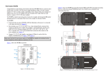
K R A ME R E LE CT R O N IC S L T D . USER MANUAL MODEL: F-121 XGA/Audio Line Transmitter Mounting Box for Ackermann Floor Boxes P/N: 2900-000715 Rev 2 Contents 1 Introduction 1 2 2.1 2.2 2.3 3 3.1 3.2 3.3 3.4 Getting Started Achieving the Best Performance Safety Instructions Recycling Kramer Products Overview Defining the F-121 Description About the Power Connect™ Feature Shielded Twisted Pair (STP) / Unshielded Twisted Pair (UTP) DDC Support 2 2 2 3 4 4 7 7 7 4 4.1 4.2 4.3 4.4 4.5 4.6 Connecting the F-121 Installing a Kramer Insert Connecting the Cables to the Rear Side of the F-121 Installing the F-121 inside the Ackermann Floor Box Connecting the Front Panel Ports Wiring the 8-pin Terminal Block Line Output Connector Wiring the TP LINE IN / LINE OUT RJ-45 Connectors 8 8 8 9 10 10 11 5 Technical Specifications 12 Figures Figure 1: The F-121 XGA / Audio Line Driver Mounting Box Figure 2: F-121 Fitted in an Ackermann Floor Box Figure 1: F-121 XGA Line Transmitter Mounting Box Figure 2: Installing the F-121 XGA / Audio Line Transmitter Mounting Box Figure 3: Terminal Block Pinouts Figure 4: TP PINOUT 5 5 6 9 10 11 F-121 – Contents i U U U U U U U U U U U U 1 Introduction Welcome to Kramer Electronics! Since 1981, Kramer Electronics has been providing a world of unique, creative, and affordable solutions to the vast range of problems that confront video, audio, presentation, and broadcasting professionals on a daily basis. In recent years, we have redesigned and upgraded most of our line, making the best even better! Our 1,000-plus different models now appear in 11 groups that are clearly defined by function: GROUP 1: Distribution Amplifiers; GROUP 2: Switchers and Routers; GROUP 3: Control Systems; GROUP 4: Format/Standards Converters; GROUP 5: Range Extenders and Repeaters; GROUP 6: Specialty AV Products; GROUP 7: Scan Converters and Scalers; GROUP 8: Cables and Connectors; GROUP 9: Room Connectivity; GROUP 10: Accessories and Rack Adapters and GROUP 11: Sierra Products. Congratulations on purchasing your Kramer F-121 XGA / Audio Line Transmitter Mounting Box, which is ideal for the following typical applications: • Presentation venues • Multimedia applications • Long-range graphics distribution for schools, hospitals, security, and stores F-121 - Introduction 1 2 Getting Started We recommend that you: • Unpack the equipment carefully and save the original box and packaging materials for possible future shipment • Review the contents of this user manual • Use Kramer high-performance, high-resolution cables i 2.1 Go to http://www.kramerelectronics.com to check for up-to-date user manuals, application programs, and to check if firmware upgrades are available (where appropriate). Achieving the Best Performance To achieve the best performance: • Use only good quality connection cables to avoid interference, deterioration in signal quality due to poor matching, and elevated noise levels (often associated with low quality cables) • Do not secure the cables in tight bundles or roll the slack into tight coils • Avoid interference from neighboring electrical appliances that may adversely influence signal quality • Position your Kramer product away from moisture, excessive sunlight and dust 2.2 Safety Instructions ! ! 2 Caution: There are no operator serviceable parts inside the unit Warning: Use only the Kramer Electronics input power wall adapter that is provided with the unit Warning: Disconnect the power and unplug the unit from the wall before installing This equipment is to be used only inside a building. It may only be connected to other equipment that is installed inside a building. F-121 - Getting Started 2.3 Recycling Kramer Products The Waste Electrical and Electronic Equipment (WEEE) Directive 2002/96/EC aims to reduce the amount of WEEE sent for disposal to landfill or incineration by requiring it to be collected and recycled. To comply with the WEEE Directive, Kramer Electronics has made arrangements with the European Advanced Recycling Network (EARN) and will cover any costs of treatment, recycling and recovery of waste Kramer Electronics branded equipment on arrival at the EARN facility. For details of Kramer’s recycling arrangements in your particular country go to our recycling pages at http://www.kramerelectronics.com/support/recycling/. F-121 - Getting Started 3 3 Overview The F-121 mounting box for Ackermann floor boxes is a twisted pair transmitter for computer graphics video signals up to and exceeding UXGA and unbalanced stereo audio. It converts the input signals into a twisted pair signal that it transmits to a compatible twisted pair receiver (for example, the Kramer TP-122). The F-121 includes two adjacent openings that lets you fit two single inserts or one dual insert into the device. In particular, the F-121 transmitter features: • A transmission range of more than 300ft (more than 100m), and a 20kHz audio bandwidth with an S/N ratio that exceeds 80dB on the same transmission range • The capability to store EDID when programmed by the Kramer FC-200 XGA EDID Copier The EDID of the display on the transmitter can be captured via the FC-200. 3.1 • Resolutions of up to UXGA • The Kramer Power Connect™ feature • A 12V DC power supply Defining the F-121 Description This section defines the F-121. Figure 1 shows the F-121 XGA / Audio Line Transmitter Mounting Box: 4 F-121 - Overview Figure 1: The F-121 XGA / Audio Line Driver Mounting Box Figure 2 shows the F-121 fitted in an Ackermann floor box: Figure 2: F-121 Fitted in an Ackermann Floor Box F-121 - Overview 5 Figure 3: F-121 XGA Line Transmitter Mounting Box # 6 Feature Function 1 Mounting Tabs For fitting the F-121 into an Ackermann floor box 2 Blank Inserts (2) Replace with Kramer wall plate inserts (see Section 4.1) 3 PC IN 15-pin HD F Connector Connect to the XGA source 4 Slide Screws (2) Release to increase or decrease the length of the unit; tighten to fix size 5 Adjustable Mounting Slide For adjusting the size of the unit to fit an Ackermann floor box 6 ON LED Lights red when receiving power, lights green when receiving a signal from a video source 7 AUDIO IN 3.5mm mini Connector Connect to an unbalanced stereo audio source 8 8-pin Terminal Block Line Output Connector Connect to the line in connector on the receiver (see Section 4.5) (located inside the mounting box) F-121 - Overview 3.2 About the Power Connect™ Feature The Power Connect feature applies as long as the cable can carry power. This feature is available when using STP cable and the distance does not exceed 50m (164ft) on standard CAT 5 cable. For longer distances, heavier gauge cable should be used (TP cable is still suitable for the video/audio transmission, but not for feeding the power at these distances). For units which are connected via RJ-45 connectors, make sure that the shield of the STP cable is connected to the metal casing of the connectors on both ends of the cable. For units which are connected via terminal block connectors, the shield of the STP cable must be connected to a ground terminal on the units at both ends (use the ground terminal of the power supply connection if necessary). For a TP cable exceeding a distance of 50m, separate power supplies should be connected to the transmitter and to the receiver simultaneously. 3.3 Shielded Twisted Pair (STP) / Unshielded Twisted Pair (UTP) We recommend that you use Shielded Twisted Pair (STP) cable, and stress that the compliance to electromagnetic interference was tested using STP cable. There are different levels of STP cable available, and we advise you to use the best quality STP cable that you can afford. Our non-skew-free cable, Kramer BC-STP is intended for analog signals where skewing is not an issue. In cases where there is skewing, our Unshielded Twisted Pair (UTP) skew-free cable, Kramer BC-XTP, may be advantageous, and UTP cable might also be preferable for long range applications. In any event when using UTP cable, it is advisable to ensure that the cable is installed far away from electric cables, motors and so on, which are prone to create electrical interference. 3.4 DDC Support When establishing a VGA connection between a PC or laptop and a display device, a set of parameters known as EDID is exchanged between them, which is carried over the DDC channel. In some PC graphic cards and laptops, this information exchange is essential for proper VGA OUT operation. F-121 - Overview 7 4 Connecting the F-121 i Always switch off the power to each device before connecting it to your F-121. After connecting your F-121, connect its power and then switch on the power to each device. To install the F-121 you have to install the inserts and the transmitter which is connected via TP to a receiver. To install the F-121, do the following: • Install the Kramer inserts (see Section 4.1) • Connect the cables to the rear side (see Section 4.2) • Install the F-121 inside the Ackermann floor box (see Section 4.3) • Connect the front panel ports (see Section 4.4) • Connect the twisted pair cable to the receiver (for example, the Kramer TP-122) 4.1 Installing a Kramer Insert To install a Kramer insert, do the following: 1. Unscrew the two screws holding the blank insert and remove it. 2. Place and align the required wall plate insert item over the opening. 3. Insert the two screws to fix the insert in place, and tighten them. 4.2 Connecting the Cables to the Rear Side of the F-121 To connect the rear side cables, do the following: 1. Run the cables through the Ackermann under-floor cable opening. 2. Connect the cables to the rear side of the inserts. 3. Connect the cables to the rear side of the F-121 transmitter, that is, attach the: 8 F-121 - Connecting the F-121 Terminal block line output of the F-121 to the pre-installed UTP wiring that connects to the TP receiver (for example, the Kramer TP-122 XGA / Audio Line Receiver) with a range of more than 300ft (>100m), see Section 4.5 12V DC power supply to the power terminal blocks (connect the wire labeled “+” to the +12V pin, and the wire labeled “–” to the GND pin) taking care that the polarity is correct (see Figure 5) 4.3 Installing the F-121 inside the Ackermann Floor Box To install the F-121 inside the Ackermann floor box, as illustrated in Figure 4, perform the following steps: 1. Slightly release the two slide screws (do not remove them) to let the adjustable mounting slide move freely. 2. Fit the F-121 mounting box into its designated place inside the Ackermann floor box (see Figure 2). 3. Insert the fixed tab into the slot in the Ackermann box. 4. Adjust the size of the unit to fit the space in the box. 5. Insert the tab on the adjustable mounting box to the appropriate slot in the Ackermann box. 6. Tighten slide screws to fix the size of the unit. Figure 4: Installing the F-121 XGA / Audio Line Transmitter Mounting Box F-121 - Connecting the F-121 9 4.4 Connecting the Front Panel Ports To connect the front panel ports: 1. On the F-121 transmitter section, connect: The XGA source (for example, a laptop’s graphics card) to the PC IN 15-pin HD (F) connector An audio source to the AUDIO IN 3.5mm mini jack, for example, using a Kramer C-GMA/GMA cable (VGA 15-pin HD (M) +Audio jack to VGA 15-pin HD (M) +Audio jack) Alternatively, you can connect an XGA source to the XGA INPUT 15-pin HD (F) connector, and a separate audio source to the AUDIO IN 3.5mm mini jack 2. Connect the appropriate connectors to the inserts. 4.5 Wiring the 8-pin Terminal Block Line Output Connector The 8-pin terminal block is an easy plug-in connector for attaching the UTP cable. Follow the colors of the color-coded sticker on these terminals for proper connection of the UTP cable. Figure 5 defines the pinouts for the terminal block. Figure 5: Terminal Block Pinouts Notes: • Use the connector clips only when removing wires, not when inserting them • Each wire should protrude 9mm (0.35in) from the plastic insulation so that it can be easily connected. To prevent the wires crossing, be sure that each wire is fully inserted 10 F-121 - Connecting the F-121 4.6 Wiring the TP LINE IN / LINE OUT RJ-45 Connectors This section defines the TP pinout, using a straight pin-to-pin cable with RJ-45 connectors. EIA /TIA 568B PIN 1 Wire Color Orange / White 2 Orange 3 Green / White 4 Blue 5 Blue / White 6 Green 7 Brown / White 8 Brown F-121 - Connecting the F-121 Figure 6: TP PINOUT 11 5 Technical Specifications INPUTS: 1 UXGA on a 15-pin HD (F) connector 1 Unbalanced stereo audio on a 3.5mm mini connector 1 Power 12V DC on 2-pin terminal block OUTPUTS: 1 UTP on an 8-pin terminal block with springs MAX. OUTPUT LEVEL: Video: 1.9Vpp Audio: 2.7Vpp RESOLUTION: Up to UXGA AUDIO BANDWIDTH: 20kHz DIFF. GAIN: 5.8% DIFF. PHASE: 0.5 Deg K-FACTOR: <0.05% S/N RATIO: Video: 60dB @5MHz Audio: 78dB @ 1KHz CONTROLS: Video detection LED COUPLING: Video: AC Audio: AC AUDIO THD + NOISE: 0.04% AUDIO 2nd HARMONIC: 0.001% POWER SOURCE: 12V DC 390mA (feeding TP-122-od receiver); self current 110mA OPERATING TEMPERATURE: 0° to +40°C (32° to 104°F) STORAGE TEMPERATURE: -40° to +70°C (-40° to 158°F) HUMIDITY: 10% to 90%, RHL non-condensing DIMENSIONS: Closed: 7.5cm x 15.7cm x 4.4cm (2.95” x 6.18" x 1.73") W, D, H Open: 7.5cm x 15.7cm x 4.4cm (2.95” x 6.18" x 1.73") W, D, H WEIGHT: 0.19kg (0.42lbs) approx. ACCESSORIES: Power supply Specifications are subject to change without notice at http://www.kramerelectronics.com U 12 U F-121 - Technical Specifications For the latest information on our products and a list of Kramer distributors, visit our Web site where updates to this user manual may be found. We welcome your questions, comments, and feedback. Web site: www.kramerelectronics.com E-mail: [email protected] ! P/N: SAFETY WARNING Disconnect the unit from the power supply before opening and servicing 2900- 000715 Rev: 2