1
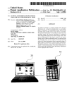
USER'S MANUAL
Thank you for purchasing our infrared wireless microphone system. Please be sure to
read the manual thoroughly to be fully familiarized with its functions and keep it for future
reference.
SYSTEM CONFIGURATION
1
PIRA250
Base Station Receiver
5
2
3
Power Supply
for PIRA250
MIW333
Beltpack Transmitter
6
7
4
MIW335
Handheld Transmitter
8
PIRT33
Mic Interface Sensor
ML63
Lavalier Microphone
MLI63
Short Microphone
9
10
11
12
MHS63
Headset Microphone
MC63
Collar Microphone
PIRS360
Ceiling Sensor
PIRS120
Wall Sensor
MIR63
IR Emittor Microphone
13
XC33
Charging Station
INFRARED RECEIVER
PIRA250 FRONT PANEL
1
2
Parts and Functions:
1. Power switch
2. Audio indicator
3. IR1 reception indicator
4. IR2 reception indicator
5. IR1 volume control
6. IR2 volume control
7. Low-tone control
3
4
5
6
7
8
9
10
11
12
13
14
8. Mid-tone control
9. High-tone control
10. Aux1 volume control
11. Aux2 volume control
12. Aux3 volume control
13. Line-in volume control
14. Volume control of assistive listening device
REAR PANEL
1
2
3
4
5
6
7
8
9
10
11
12
Parts and Functions:
1.External sensor input-Allows 3 external sensors to be used with this system.
2.Mic In volume control
3.Mic In
4.Aux In-Allows 3 audio sources to apply to this system.
5.Line Out
6.Audio output connector for assistive listening device. The volume level can be adjusted individually via the
volume knob (14) on the front panel of PIRA250.
7.Emergency Override-When this function is activated, all operation of this unit will be stopped temporarily,
emergency audio source will be amplified through this input. This function is specifically designed for
emergency or public broadcast.
8.Sensitivity setting of emergency override (EO)-Clockwise to increase the sensitivity of EO.
9.Volume setting of EO-Clockwise to increase the volume of EO.
10. Main speaker out
11.DC output-Provides power supply to another system such as XC33.
12.DC In
Handheld Transmitter MIW335
Parts and functions
1.Grille cover.
2.Status LED: Bicolor LED will glow when switch is put to ON :
Green : Battery is full and transmitter is in normal mode.
Red : Battery is weak and will shut off soon. Please charge the battery.
3.Power switch
Slide to turn microphone on or off.
4.Battery compartment.
5.Infrared emitter with charging contacts.
(IR ray radiates from here. Do not block or hold this part of the body.)
6.Channel selector. A stands for 2.08MHz and B stands for 2.54MHz.
7.Sensitivity control. Clockwise to increase sensitivity level. Factory preset is max level.
Battery Installation/Replacement
Turn the battery cover counterclockwise and pull out. As shown in figure.
Make sure the power switch is in OFF position when installing or replacing batteries.
And then install the new battery according to its correct polarity.
A. Battery installation (2100mA / 2.4V x 1)
B. Battery installation ( AA x 2)
1
2
battery sleeve
3
4
Beltpack Transmitter MIW333
Part and functions:
5
6
8
9
1 42 3
10
7
1.Volume control
2.Bi-color Power / Battery status indicator:
3.Power switch
4.mini XLR socket
5.Infrared emitter
6.Cover-release button
7.Charging contacts
8.Emission power selector
9.Channel selector
10.MT gain control
Various Settings in MIW333
Channel Selection:
First open the cover of MIW333's battery compartment by pressing its release buttons on
both sides. There are 2 channels for selection, namely "A" and "B" A stands for 2.08MHz
and B stands for 2.54MHz.
Making Changes to MT:
Low-impedance "MT" gain control is located inside the battery compartment. It can be
adjusted by using a small screw driver to rotate till a desired audio output level is selected.
BATTERY OPERATING TIME
Continuous operating time of fully charger Ni-MH 2100mA/2.4v battery is as follows:
Emission Power level
Operating time
Lo position
Hi position
6 hours
4 hours
*Operating times are approximate and not guaranteed.
Battery installation/replacement
T o install the batteries, first open the battery compartment by pressing the release
buttons on both sides of the MIW333. Batteries used are 2 pcs of NiMH 1.2V/2100 mAH
type(rechargeable) or Alkaline type(not rechargeable). When inserting batteries, please
place them according to the correct polarity.
Various Microphones for the MIW333
1. MIR63
Parts & Functions
3
1
1. mini XLR connector
2. IR emitter
3. mic capsule
2
Usage: Plug the XLR connector to the XLR socket of MIW333.
2. PIRT33
Parts & Functions
2
1. mini XLR connector
2. IR emitter
3. clip
4. mic input
4
3
1
Assistant microphones for PIRT33
ML63
Lavalier Microphone
MHS63
Headset Microphone
MC63
Collar Microphone
MLI63
Short Microphone
Usage: Plug the XLR connector of ML63 / MHS63 / MC63 / MLI63 to the XLR
socket of PIRT33.Then plug this set into the MIW333.
Charging Station XC33
Parts and Functions:
1 2 3 4
1.Fully charged
2.Charging
3.Charging (Rear)
4.Fully charged (Rear)
5
6
7
8
5.DC input
6.DC output
7.Charging socket (Rear)
8.Charging cable
Charging the transmitters:
1.Make sure that the batteries installed in the transmitter are rechargeable NiMH type
and transmitter power has been turned off.
2.Connect the adaptor to the DC IN port of XC33 with its end to the wall outlet or DC
output of PIRA250.
3.Place the transmitter into the slot and charging process will start automatically.
4.When another transmitter has to be charged simultaneously, simply connect a
charging cable between the external charging port and this transmitter.
5.There are 2 sets of LED to indicate the charging condition of both transmitters.
The left set indicates the front transmitter and the right for the rear one. During
charging the RED LED will keep lit. When charging is finished, the process will stop
automatically and the GREEN LED will light up.
CAUTION!!
The above chargers are specially designed for Ni-MH battery used in portable
transmitters/receivers only. Before charging, please make sure that the batteries are
Ni-MH rechargeable type.
Never try to charge an ordinary Zinc oxide or Alkaline battery as this may result in
explosion or fire.
OPERATING THE SYSTEM
1. Plug the adaptor in a nearby outlet and then connect the DC plug of adaptor to your
receiver.
2. Connect the receiver to speaker and turn on the PIRA250.
3. Slide the power switch of microphone to "ON". Then the channel indicator of receiver
will light up.
4. Adjust the volume control of amplifier to a comfortable level.
5. Find the best position with a wide view of the room then set the receiver.
CAUTIONS:
‧Do not cover the infrared emitter area of the wireless microphone or the surface of the
infrared sensor, which may disturb the unit and cause abnormal operation.
‧Since the unit uses infrared reflectance. Do not expose receiver to the black ceiling or
wall which may cause abnormal operation.
‧Do not use the microphones near speakers which may cause feedback.
‧Prevent the microphone from getting wet and avoid dropping.
‧Do not replace the battery when power is on.
‧Do not install the unit near heat source or in a place subject to direct sun-light, excessive
dust, mechanical vibration or shock.
Ceiling Sensor PIRS360
PIRS360 has a wide reception of 360-degree angle to see the entire room at once.
Users can select 1, 2 or more PIRS360 to operate with PIRA250 receiver according to
different locations. Below are 2 examples for sensor placement of 1 and 2 PIRS360 in two
applications.
A.In an ordinary space such
as a classroom
1.Locate the PIRS360 sensor in the middle of the ceiling (as
illustrated in below picture).
2.Connect the sensor cable to
PIRA250.
3.Turn on the IR system and
amplifier then operation can be
started.
B.In a larger space such as
a fitness center
ceiling sensor
1.Locate 2 PIRS360 sensors on
the suggested positions on the
imaginary catercorner of the
ceiling (as illustrated in below
picture).
2.Connect both sensor cables to
PIRA250.
3.Turn on the IR system and
amplifier then operation can be
started.
ceiling sensor
Specification:
PIRA250: Base Station Receiver
ITEM
Receiving frequency
Modulation
IR frequency response
Speakers
Speakers output power
Acoustic output
Auxiliary input level
Auxiliary input impedance
Signal-to-noise
Image rejection
THD
Maximum deviation
Squelch
Squelch level / Reception
sensivity
Power supply
User controls
PRODUCT SPECIFICATIONS
2.08MHz & 2.54MHz
FM wide-band
50Hz to 12kHz
6 to 8 Ω
50W+50W (4 Ω) / 25W+25W (8 Ω)
90dBa ± 3dB @ 1m into 8 Ω
-18dB ± 3dB
15k Ω, Nominal
>65dB
>40dB
<1% @ 1kHz into 8 Ω
± 22k Hz
RF carrier/tone control
32 dBuV ± 2 dBuV
Input : 100~240VAC / 50-60Hz /1.5A (typical, with switching adaptor)
Output : 24V / 2.5A (60W)MAX (typical, with switching adaptor)
@ might change 20V or 28V
Power on; AUX1 & AUX2 & AUX3 & IR1 & IR2 volumes; 3-band
equalizers; mic volume (back); EO sens (back); EO level (back).
Displays
LEDs for "IR1"; "IR2"; "AUDIO"; Red IR1 & Yellow IR2 LED indicates IR
signal reception; Green LED indicates audio signal reception.
Color
Size
Weight
Case
Operating range
Reception area
Reception angle
Inputs/outputs
Black case,plastics front face
42 x 18.8 x 4.5cm/16.5 x 7.4 x1.77in
1.6kg/3.7lbs, 1.93kg/4.45lbs (with switching adaptor)
Steel, baked enamel finish, solid ABS plastic front face
20 m line-of-sight (typical, with ceiling sensor)
240 m² (typical with ceiling sensor)
360° full semi-spherical (half dome coverage; typical, with ceiling sensor)
3 RCA stereo (L/R) aux in jacks; RCA stereo (L/R) line out jack; 3 RCA
jacks for external sensor connection; 2.0mm input power jack; 2.0mm
output power jack; 5.08mm combicon connector for main speaker out
connection; 3.81mm mini-combicon connector for emergency override
connection; 3.81mm mini-combicon connector for mic in connection.
10
ITEM
Transmitting frequency
Modulation
Frequency response
Operating range
Transmission angles
Microphone type
User controls
Inputs/outputs
Battery life
Size
Weight
Case
ITEM
Transmitting frequency
Modulation
Frequency response
Transmission angle
Audio distortion
Microphone type
User controls
Battery life
Size
Weight
MIW333: Beltpack Transmitter
PRODUCT SPECIFICATIONS
2.08MHz & 2.54MHz (switchable)
FM wide-band
50Hz to 10kHz
20 m line-of-sight
160° horizontally; 40° vertically
uni-directional hyper-cardioid
Switch [on/off]/volume/channel (A/B)/sensitivity (MT)/power(Hi/Lo)
5 pin XLR mic input; 0.6x0.6mm charge bomb-splinter.
maximum 8 to 9 hours @ Hi power (dual AA, 2600mAh rechargeable
NiMH)
maximum 16 to 18 hours @ Low power (dual AA, 2600mAh rechargeable
NiMH)
7x10.5x2.9cm/2.8x4.1x1.2in
90g/0.21lbs, 140g/0.32lbs (with batteries), 170g/0.39lbs (with batteries and
MIR-63)
ABS plastic
MIW335: Handheld Transmitter
PRODUCT SPECIFICATIONS
2.08MHz & 2.54MHz (switchable)
FM wide-band
50Hz to 12kHz
360° radial
<1.0% (± 15kHz deviation @ 1kHz)
uni-directional dynamic
Switch [on/off]/channel (A/B)/sensitivity
maximum 8 to 9 hours (dual AA, 2600mAh rechargeable NiMH)
23.7x5.7cm/9.3x2.2in
230g/0.53lbs, 300g/0.7lbs (with batteries)
Aluminum, baked enamel finish
11
ITEM
Operating frequency
Operating range
Signal/Power interface
Number of IR LEDs
Power indicator LED
Reception area
PIRS360: Ceiling Sensor / PIRS120: Wall Sensor
PRODUCT SPECIFICATIONS
Sensor wire
2.08MHz & 2.54MHz
2.08MHz & 2.54MHz
20 m line-of-sight (typical)
20 m line-of-sight (typical)
F-female jack, 8" lead
F-female jack, 8" lead
6
6
Red
Red
240 m² (typical with receiver)
240 m² (typical with receiver)
360° full semi-spherical (half dome 180° full semi-spherical (half dome
coverage)
coverage)
11x3.9 cm/4.33x1.54in
11x3.9 cm/4.33x1.54in
210g/0.48lbs (with bracket)
210g/0.48lbs (with bracket)
Drop ceiling acoustic tile or
Drop ceiling acoustic tile or sheetrock
sheetrock ceiling
ceiling
10m (RCA male-to-male) Flexible 10m (RCA male-to-male) Flexible
Plenum Jacket Type
Plenum Jacket Type
Case
Plastic, solid steel bracket
Reception angle
Dimensions
Weight
Mounting
ITEM
Input voltage
Charge time
Charge rate
Charge detect
Protection
Operating temperature
range
Suitable batteries
User controls
Displays
Size
Weight
Case
Plastic, solid steel bracket
XC-33: Charging Station
PRODUCT SPECIFICATIONS
12VDC 500mA (SUPPLIED FROM PIRA-250 OR OPTIONAL (PX33) AC
ADAPTER)
maximum 8 to 9 hours
300 mA @ 8V (C/6)
Peak voltage and Timeout
Shorting protection; peak voltage protection; over charging
0 -35°C on cell surface
dual AA, 2400 ~ 2700mAh rechargeable NiMH
Discharge button
LEDs for "FULL"; "CHG."; "COND."; Green LED indicates fully charged;
Red LED indicates charging; Yellow LED indicates discharging; 2.0mm
input power jack; 2.0mm output power jack.
12x10x9.3cm/4.7x3.9x3.7in
180g/0.42lbs, 490g/1.13lbs (with 12VDC/500mA adaptor)
ABS Plastic
12
CUSTOMER SERVICE
REPLACEMENT PARTS
Please provide complete information when you request
replacement parts from either the Factory or a Paso Authorized
Distributor. Be certain to include the Part Number and Description
as it appears on the parts list, the Model Number of the unit and if
possible the Serial Number and the date of purchase of the unit.
Replacement parts inventory is maintained specifically to repair
Paso products. Part sales for other reasons or applications will be
declined.
REPAIR SERVICE
Repair service for out of warranty Paso products may be
obtained form your local Paso distributor or any other
qualified repair station.
ORDERING FROM THE FACTORY
Print all information on a purchase order form and mail to:
PASO SOUND PRODUCTS, INC.
4750 Goer Drive - Building F
CHARLESTON, SC 29406
IN WARRANTY REPAIR SERVICE
Call or write the Factory to obtain an authorization to
return
the product for repairs.
Be sure to include the following:
- Paso part number
- Part description
- Quantity required
- Model number of the unit
- Serial number of the unit
- Your payment or your authorization for COD shipment for parts
not covered by the Warranty or if your company has a current
account with the factory
RETAIN ORIGINAL PARTS (IN WARRANTY) UNTIL YOU
RECEIVE REPLACEMENTS. DEFECTIVE PARTS THAT
SHOULD BE RETURNED TO THE FACTORY WILL BE LISTED
ON YOUR PACKING SLIP.
For your convenience replacement parts are also available through
Paso Authorized Distributors and Dealers nation wide. Obtain a
location list directly from the Factory or your regional Paso
Representative.
In warranty repairs must be returned to the Factory.
Prior authorization must be obtained from the Factory.
Products received without authorization will be refused by
our Receiving Department.
Pack the equipment in the original carton or in a strong
carton with at least THREE INCHES of resilient packing
material on all sides, top and bottom. Seal the carton with
reinforced tape and mark it FRAGILE on at least two
sides. Remember, the Carrier will not accept liability for
shipping damages if the unit is improperly packed.
EQUIPMENT RECEIVED IN DAMAGED CONDITION
DUE TO POOR PACKING WILL BE REFUSED AND
THE WARRANTY COVERAGE IS AUTOMATICALLY
VOIDED.
The Paso Sound Limited Warranty provides:
The examination of the returned product must disclose in
our judgement, a manufacturing defect. The warranty
does not extend to any product that has been subject to
misuse, neglect, accident, improper installation or where
the serial number of the product has been removed or
defaced.
Ship via insured prepaid United Parcel Service or Parcel
Post to:
TECHNICAL CONSULTATION
- Need help with your installation ?
- Need help with the operation of the unit ?
- Need help with a repair ?
Call or write for assistance. You will find our Technical Dept. eager
to help or assist you with any technical problem you may have
encountered except “`Customizing'' for a unique application.
The effectiveness of our consultation service depends on
the accuracy of the information you furnish.
Be sure to tell us:
- The Model and Serial number of the unit
- The date of purchase
- An exact description of the difficulty
- All trouble-shooting done in attempting to correct the problem
Call our toll-free phone number:
1-800 231 3034
PASO SOUND PRODUCTS, INC.
4750 Goer Drive - Building F
CHARLESTON, SC 29406
ATTN. SERVICE DEPARTMENT
The equipment will be returned freight prepaid after
repairs.
Be sure to include the following:
- Your name and address
- Date of purchase and copy of invoice
- A brief description of the difficulty
- A return address shipping label
OUT OF WARRANTY REPAIR SERVICE
Follow return instructions as per in warranty repair
service. Prior to performing all necessary repairs, you will
be advised of the charges and at that time a written
authorization by you will be required including
authorization to return the equipment COD for the service
and shipping charges. This will avoid unnecessary delays
Paso Sound Products, Inc.
Web site: http://www.pasosound.com
E-mail: [email protected]
475 0FGoer Drive- Charleston , Sout h Carolina29406 / TEL: 1-800-231-303 4 FAX : 843-308-0904
Printed in ROC 2008
Printed in USA 2008
Manual
OM 237
REV. 1.0


![13.56MHz [MIFARE] Contactless Smart Card](http://vs1.manualzilla.com/store/data/005689074_1-1b5ba2b7f854420e24ee51932ec4423a-150x150.png)