1
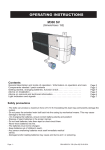
O P E R AT I N G I N S T R U C T I O N S
M400 Fingerprint
Contents
General and operating description, care instructions
Page 2
Technical specifications
Page 3
Assembly instructions and sequence of steps
Page 4
Tips for troublefree operation
Page 5
Learn master finger
Page 6
Learn user finger
Page 7
Opening and locking the M400 FP
Page 8
Automatic delayed locking
Page 9
Master Reset
Page 10
Hardware Reset
Page 11
Learn several master fingers
Page 12
Battery warning, changing batteries
Page 13
Troubleshooting
Page 14
Safety precautions
On changing the batteries, ensure correct battery polarity and position!
- Dispose of spent batteries in the proper manner!
- Do not heat the batteries, take them apart of short-circuit them!
- Never throw batteries into naked flames!
- The batteries must not be recharged!
- Keep the batteries out of children's reach!
- Any person swallowing batteries must seek immediate medical
advice!
- Damaged and/or leaking batteries may lead to acid burns and/or poisoning!
Page -1-
Gener al description
Page -2-
The M400 is a biometric locking system for furniture. It is intended for indoor use in home and office
furniture. It must not be used out of doors or in wet areas. The system can learn between 1 and 3
master fingers and up to 50 different user fingers altogether. This manual contains all the information
needed to ensure troublefree installation and operation of the M400 system.
Wording and graphics have been prepared for you with care. However, no liability will be assumed for
any mistakes that may have occurred. Copyright 2011 by LEHMANN Vertriebsgesellschaft mbH, D32429 Minden. All rights reserved. These instructions must not be reproduced in any way (print,
photocopy, microfilm or other process) or processed, duplicated or distributed using electronic systems
either in whole or in part without written consent from LEHMANN Vertriebsgesellschaft mbH. We
reserve the right to change the scope of supply and/or introduce technical changes without prior notice
if necessary for manufacturing reasons.
Please keep this manual in a safe place for future reference.
Oper a ting description
Furniture units can be conveniently locked and unlocked electronically with the biometric electronic
locking system M400 FP. The M400 system allows you to issue selective access authorisations so that
only authorised personnel are given access to specific items of furniture. The system is programmed
and operated without requiring any additional devices.
The M400 FP works autonomously, without being connected by cable to other control electronics or the
power supply system. The system can learn up to 50 different user fingers quickly and simply using any
electronic control unit.
Once the system has successfully been programmed, the furniture lock automatically executes a locking
process whenever an authorized user finger passes over the previously activated sensor. A master
finger cannot trigger a locking process. It is exclusively used to program the system.
Advice on oper
a tion and car
e
For hygiene reasons, biometric systems with human contact should be cleaned at regular intervals.
Material adhering to the sensor or fingers can interfere with the system and possibly prevent correct
recognition of duly authorized fingers.
The following instructions should therefore be observed.
- Do not pour any liquids into or over any of the system's components and never immerse the
components in liquids.
- Always clean the system and particularly the sensor with a soft, clean, slightly damp cloth.
- Do not use any cleaning products containing abrasives or solvents. Glass cleaning agents, thinner,
alcohol, benzene and cleaning agents containing ammonia must not be used, as these agents will
corrode the housings and cause lasting damage.
- Treating any of the electronic and mechanical components improperly or in any way other than
described in this user manual may lead to malfunctions and thus invalidate the warranty.
- Under no circumstances should the housing of the electronic control or fingerprint unit be opened.
Only the battery compartment may be opened to replace the batteries. Any violation of this requirement
will likewise invalidate the warranty.
T r oubleshooting
Page -14-
Please always check the following points before requesting support:
Page -3-
Page -2- and -5Page -3- and -11-
Storage capacity for max. 3 master fingers and up to 50 user fingers.
Page -6- to -10-
Storage capacity for
max. 3 master fingers and
up to 50 user fingers.
Page -4-
- If the problem cannot be remedied, please reset the system and then
reprogram it.
Page -9-
Page -5-
P ac ka ge contents
Protector
tions
Power supply of the electronic control: Battery type: 2 x AA mignon cells, alkaline 1.5 V.
NiCd, NiMH and other rechargeable batteries, as well as zinc-carbon or lithium batteries must not be
used!
Temperature range:
Operation = +5 °C to +40 °C at 30% to 80% relative humidity, non-condensing.
Storage = -25 °C to +70 °C at 30% to 80% relative humidity, non-condensing.
- Have all cables and plugs been connected correctly?
- Is the sensor perhaps soiled or is the finger injured? Please note the
advice on operation and care.
- Do the batteries have sufficient power? Note the battery warning indicators
and the information in the technical specifications.
- Are the corresponding light signals actually output during operation of the
system?
- Has your fingerprint been recognized correctly and saved in the system?
Please note the instructions and tips for troublefree operation.
M400 FP
T ec hnical specifica
Fingerprint module
with 100 mm connecting cable
M400 FP
Furniture lock
Cover
Fingerprint
2x 1,5V AA
Striker plate
OPERATIN
INSTRUCTIONS
Mignon
Mignon
3x Spax 3x13
1 set of batteries
2 x AA mignon cells,
alkaline 1.5 V
2x DIN 7982
2,9x25
2x Spax 3x30 2x Spax 3x13
Installed situation
Connecting cable
100 mm
Battery compartment lid
with locking screw
Bolt protector
and striker plate
Hole
pattern
M400 FP Furniture lock
Fingerprint Module
Striker plate
Assembl
y sequence
Step 1
Page -4-
Step 2
Step 3
Step 4
Ba tter y w ar ning
Page -13-
The M400 provides you with several low-battery warning stages (see table below).
Warning stage
Stage 1
Display
Battery voltage is low.
Batteries should be
replaced
Normal operation
is still given.
Indicator flashes
3 x red
Battery power is
exhausted. Batteries
must be changed.
The lock now only
performs the
"UNLOCK" command
whenever actuated.
Screw down electronics
Slip on
bolt protector
Step 6
Effect
Indicator flashes
2 x red
Stage 2
Step 5
Meaning
Step 7
Step 8
Changing ba
tteries
Change batteries.
Make sure they are fitted the right way round.
Close lid on battery compartment.
Screw in fastening screw.
Undo screw.
Open lid on battery
compartment.
-
Battery type:
LR6, AA, alkaline
+ +
-
CAUTION: NiCd, NiMH and other rechargeable batteries, as well as zinc-carbon or lithium
batteries must not be used!
Connect cable. Ensure
correct polarity of the plugs.
Step 9
Step 10
Fit cap.
Caution!
Do not damage cable
when screwing parts together.
Step 11
Monitoring the bolt position
The M400 has an internal sensor to determine the bolt limit position. If the bolt does not move into the
limit position after a locking command, a visual warning is output (red LED flickers). This means that
the furniture may not be properly locked. In such a case, check whether the bolt might have become
blocked.
Step 12
Test function
Insert batteries, ensuring
correct polarity.
Fit battery compartment lid
and secure with screw
1
Block and hold the bolt
until locking operation
is complete.
3
Warning signal
Red indicator flickers
2
Locking the M400
Lear n se v er al master finger
s
Page -12-
In contrast to the "standard application", up to 3 different master fingers can be saved in the system.
This may be useful, for example, if administration of the lock is to be granted to several people. When
programming the system, it is important to ensure that the master fingers are readily identified, as each
master finger should only be read once by the sensor of the fingerprint unit. For this programming
version and unlike the case with the standard procedure (in which a master finger is scanned three
times), the fingerprint sensor must optimally recognize the master finger when it is scanned for the first
time.
10 Golden R
ules
Page -5-
Instructions and tips for troublefree operation
Please note the following instructions for operation of the fingerprint system.
The fingerprint system is always programmed after delivery. This means that the first finger following
activation of the system is identified and saved as master finger. It is therefore particularly important to
carefully follow the instructions below.
1. The master finger should never be learned as a user finger.
Step 1
2. After recording each finger (i.e. after drawing a finger over the sensor), always wait approx. 3 s until a
signal is output by the corresponding LED and the next finger can be drawn over the sensor.
Display
3. Draw the finger over the sensor smoothly and with moderate pressure.
Briefly press the button
Both indicators light up.
System expects an input.
Step 2
5. Scarred / injured fingertips should not be used as user or master finger. Please choose a different
finger instead.
1. - Master - Finger
Place the finger
on the surface
and draw it
downwards
smoothly.
Step 3
Indicators briefly go out
Both indicators light up.
System expects an input.
2. - Master - Finger
6. It is advisable to learn the individual user fingers 3 times in order to optimize the recognition rate. In
the case of "difficult" fingers, it may be necessary to learn one and the same user finger up to 6 times or
to choose a different user finger instead.
7. One and the same finger can be drawn over the sensor several times during the programming
process. Despite this, only one storage location will be occupied (i.e. one user). This is possible
because the system can learn and logically optimize striking features of the fingerprint in the software.
8. The thumb is a good alternative if the user's fingers are very slim.
9. At least two fingers should be learned for each user. This ensures that a "spare key (finger)" is always
available in case of injury.
Place the finger
on the surface
and draw it
downwards
smoothly.
Step 4
4. Ensure that as many as possible of the whorls making up the fingerprint are drawn over the sensor.
See diagrams below.
Indicators briefly go out
Both indicators light up.
System expects an input.
10. Hygiene and cleanliness are essential in the case of systems with human contact. Soiling and
adhesions can impair operation of the system.
3. - Master - Finger
Right
Place the finger
on the surface
and draw it
downwards
smoothly.
Function display
Indicators briefly go out
Activation button
Both indicators light up.
System expects an input.
Finger pad
Step 5
Wrong
Green indicator lights up and then goes out
automatically.
When the indicator is dark, this means
that the master fingers have been
programmed successfully.
Sensor
Lear n master finger
Page -6-
Important! When starting the system for the first time, the first 3 fingers are identified as master
fingers and stored in the system. Master fingers cannot be learned later
.
The following steps must therefore be completed with great care!
Always repeat the last action if the following displays do not appear. The system has a "timeout"
function. In other words, the system switches off automatically after 30 seconds if nothing is entered or if
the input is incorrect. This is indicated by a red flashing light 5 seconds before switching off. All inputs
which have not been correctly concluded on expiry of the timeout will be discarded and are not saved.
The corresponding programming section must be repeated in this case.
Har d w ar e R eset
Seite -11-
In rare cases, it may be necessary to return a system to the factory setting. Particularly, for example, if
the person(s) with the master finger are no longer available. In this case, trained and authorised
personnel can perform a "hardware reset".
Step 1
Step 2
Step 3
Programming up to 3 different master fingers in one system, see page -10- of this manual.
Legend
Master finger
Display
(example)
Required activity
with the master finger
Initial display (e.g. "OFF")
Changes to ...
User finger
New display
Required activity
with the user finger
Changes to ...
Green lights up and red flashes
Step 1
Display
Both indicators light up
Briefly press the button
Remove cover and pull the
fingerprint reader out towards
the front.
Step 4
Caution: Do not undo
cable connection.
Step 5
Unscrew the retaining clip.
Step 6
Activation button
Step 2
Reset button
Master finger
Place the finger
on the surface and
draw it downwards
smoothly.
Indicators briefly go out
Both indicators subsequently light up
again.
Repeat step 2 another
2 more times.
Step 3
When the master finger has been drawn over
the sensor for the third time, only the green
indicator still lights up and then goes out
automatically.
When the indicators are out, this means
that the master finger has been
programmed successfully
Carefully push back retaining
clip and peel protective film off
back of reader.
Locate the reset button
on the printed circuit board.
Step 5
Perform steps 1 to 4 in reverse order.
Briefly press the activation button.
The red LED must light up.
Press the reset button on the
back of the printed circuit board
and hold it down for 2 seconds.
The green LED also lights up.
The system has been reset when
both LEDs go out.
Master R
eset
Page -10-
Users cannot be deleted from the M400 FP system selectively (i.e. certain users only). A Master Reset
must be performed if one or more users are to be deleted. Please note that, in this case, the M400 FP
will be reset to the condition prevailing on delivery.
The master finger is then also deleted from the memory. The system must subsequently be
reprogrammed completely.
Important! After resetting and re-activating the system, the first 3 fingers are identified as master
fingers and stored in the system.
Step 1
Lear n user finger
Step 1
Page -7-
Display
Red indicator lights up.
System expects an input.
Display
Briefly press the button
Red indicator lights up.
System expects an input.
Briefly press the button
Step 2
Step 2
Step 3
Red indicator lights up.
System expects an input.
Red indicator lights up.
System expects an input.
Step 3
Place the master finger
on the surface a
second time and
draw it downwards
smoothly.
User finger
Place the user finger
on the surface and
draw it downwards
smoothly.
Master - Finger
Red indicator lights up.
System expects an input.
Wiederholen Sie diesen V organg
noch mindestens 2x.
Red and green indicators flash.
System expects an input.
Step 4
Master - Finger
Master - Finger
Step 4
Both indicators light up
Place the master finger
on the surface and
draw it downwards
smoothly.
Master - Finger
Place the master finger
on the surface and
draw it downwards
smoothly.
Master - Finger
Place the master finger
on the surface and
draw it downwards
smoothly.
Indicator goes out
Place the master finger
on the surface a third time
and draw it downwards
smoothly.
Programming is now
complete.
The Master Reset is now complete.
Opening the M400 FP
Step 1
Page -8-
Display
Red indicator lights up.
System expects an input.
Briefly press the button
A utoma tic delay
ed loc king
Page -9-
The M400 FP can be set to lock automatically after a delay. When this setting is activated, the system
locks automatically after the preselected time of approx. 10 seconds. This setting has the benefit that
you only have to swipe your finger over the finger scanner when opening the system.
We only advise activating this setting for the the M400 FP catch version (sprung-type lock bolt). Only
this version guarantees that the lock bolt is able to spring back on closing the door, avoiding damage to
the furniture.
On leaving the factory, the M400 FP is programmed to the setting in which an authorised finger must
be moved across the sensor for each locking function.
Activa tion: Delay
Step 2
ed loc king
User finger
LEARN socket
Place the user finger
on the surface and
draw it downwards
smoothly.
Green indicator flashes.
Input was correct.
Lock opens.
Indicators go out.
Procedure is complete.
2. Take the programming stick out again
3. Perform at least one closing cycle (open or close).
Programming
stick
4. The M400 FP is now set for delayed locking.
5. Check for correct operation by opening the furniture lock
(bolt moves into the casing). The lock bolt automatically
moves out of the casing again after approx. 10 seconds
(system is now locked).
Loc king the M400 FP
Step 1
Display
Red indicator lights up.
System expects an input.
Briefly press the button
1. Insert the programming stick into the LEARN socket and
briefly press it down (slight resistance will be felt / button
actuation).
Deactiva
tion: Delay
ed loc king
1. Repeat steps 1 to 3 (see above).
2. Automatic delayed locking is now deactivated again.
3. Check for correct operation by opening the furniture lock
(bolt moves into the casing). If the lock bolt does not
automatically move out of the casing after 10 seconds, the
setting has been changed over successfully.
User finger
Step 2
Place the user finger
on the surface and
draw it downwards
smoothly.
This function is not provided with any additional indicator as the current setting can be verified
within 10 seconds.
Red indicator lights up.
Input was correct.
Lock closes.
Indicators go out.
Procedure is complete.
Notes on potential malfunctions
If the system has not changed over (activation or deactivation of the automatic locking function),
please repeat the relevant steps. This usually means that the button has not been pressed properly
or for long enough.