1
Leon2-CIS
User’s Manual
Version: 1.0.1
November 2006
Stefan Tillich and Johann Großschädl
Graz University of Technology
Institute for Applied Information Processing and Communications
Inffeldgasse 16a, A–8010 Graz, Austria
{Stefan.Tillich,Johann.Groszschaedl}@iaik.tugraz.at
IS E C
Instruction Set Extensions for Cryptography
Supported by
Contents
1
Introduction
1.1 Overview . . . . . . . . . . . . . . . . . . . . . . . . . . . . . . . . . . . . . .
1.2 The concept of instruction set extensions for cryptography . . . . . . . . . . . .
5
5
5
2
Installation
2.1 Installing Leon2-CIS . . . . . . . . . . . . . . . . . . . . . . . . . . . . . . . .
2.2 Installing a cross-compiler system for Leon2-CIS . . . . . . . . . . . . . . . . .
6
6
7
3
Leon2-CIS configuration
3.1 Leon2-CIS version . . . . . . . . . . . . . . . . . . . .
3.1.1 Leon2 base version . . . . . . . . . . . . . . . .
3.1.2 Leon2-CIS extension version . . . . . . . . . . .
3.2 Auxiliary extensions . . . . . . . . . . . . . . . . . . .
3.2.1 Cycle counter . . . . . . . . . . . . . . . . . . .
3.2.2 Crypto configuration register . . . . . . . . . . .
3.3 Multiplier/divider configuration . . . . . . . . . . . . .
3.3.1 Multiplier/MAC unit . . . . . . . . . . . . . . .
3.3.2 SPARC V8 divide instructions . . . . . . . . . .
3.3.3 GCC support for multiply and divide instructions
3.4 Additional CIS extensions . . . . . . . . . . . . . . . .
3.4.1 Overloaded instruction FMT3:OP3=0x2C . . . .
3.4.2 Overloaded instruction FMT3:OP3=0x2D . . . .
3.5 Implementation Options . . . . . . . . . . . . . . . . .
3.5.1 AES S-box implementation . . . . . . . . . . .
3.5.2 Unified multiplier: Propagation adder type . . .
3.5.3 Unified MAC: Propagation adder type . . . . . .
4
Implementation details of the CIS extensions
4.1 Modified ripple-carry adder . . . . . . . .
4.2 Unified multiply-accumulate unit . . . . .
4.3 AES S-box unit . . . . . . . . . . . . . .
4.4 AES MixColumns unit . . . . . . . . . .
.
.
.
.
.
.
.
.
.
.
.
.
.
.
.
.
.
.
.
.
.
.
.
.
.
.
.
.
.
.
.
.
.
.
.
.
.
.
.
.
.
.
.
.
.
.
.
.
.
.
.
.
.
.
.
.
.
.
.
.
.
.
.
.
.
.
.
.
.
.
.
.
.
.
.
.
.
.
.
.
.
.
.
.
.
.
.
.
.
.
.
.
.
.
.
.
.
.
.
.
.
.
.
.
.
.
.
.
.
.
.
.
.
.
.
.
.
.
.
.
.
.
.
.
.
.
.
.
.
.
.
.
.
.
.
.
.
.
.
.
.
.
.
.
.
.
.
.
.
.
.
.
.
.
.
.
.
.
.
.
.
.
.
.
.
.
.
.
.
.
.
.
.
.
.
.
.
.
.
.
.
.
.
.
.
.
.
.
.
.
.
.
.
.
.
.
.
.
.
.
.
.
.
.
.
.
.
.
.
.
.
.
.
.
.
.
.
.
.
.
.
.
.
.
.
.
.
.
.
.
.
.
.
.
.
.
.
.
.
.
.
.
.
.
.
.
.
.
.
.
.
.
.
.
.
.
.
.
.
.
.
.
.
.
.
.
.
.
.
.
.
.
.
.
.
.
.
.
.
.
.
.
.
.
.
.
.
.
.
.
.
.
.
.
.
.
.
.
.
.
.
8
8
9
9
9
9
10
12
12
15
15
15
15
16
18
18
18
19
.
.
.
.
19
19
19
20
20
5
Software development for the Leon2-CIS
20
5.1 Using the CIS custom instructions . . . . . . . . . . . . . . . . . . . . . . . . . 20
5.2 Cryptographic reference implementations . . . . . . . . . . . . . . . . . . . . . 21
6
Simulation
21
7
Synthesis
22
2
A Description of the Leon2-CIS add-on package
A.1 HDL model . . . . . . . . . . . . . . . . .
A.2 Test suite . . . . . . . . . . . . . . . . . .
A.3 Simulation . . . . . . . . . . . . . . . . . .
A.4 Graphical configuration . . . . . . . . . . .
A.5 Synthesis . . . . . . . . . . . . . . . . . .
B Leon2-CIS instruction reference
B.1 Organization and notation . . . . . . .
B.1.1 Assembly syntax and operands
B.1.2 Functional description . . . .
B.1.3 Timing . . . . . . . . . . . .
B.1.4 Opcode . . . . . . . . . . . .
B.1.5 Configuration conditions . . .
B.1.6 Implementation options . . .
B.1.7 Related instructions . . . . . .
B.2 UMUL instruction . . . . . . . . . . . .
B.3 UMULcc instruction . . . . . . . . . .
B.4 SMUL instruction . . . . . . . . . . . .
B.5 SMULcc instruction . . . . . . . . . .
B.6 UMAC instruction . . . . . . . . . . . .
B.7 SMAC instruction . . . . . . . . . . . .
B.8 WRA instruction . . . . . . . . . . . .
B.9 RDA instruction . . . . . . . . . . . .
B.10 MULGFS instruction . . . . . . . . . .
B.11 MULGFS2 instruction . . . . . . . . . .
B.12 GF2MUL instruction . . . . . . . . . .
B.13 GF2MAC instruction . . . . . . . . . .
B.14 SHACR instruction . . . . . . . . . . .
B.15 UMAC2 instruction . . . . . . . . . . .
B.16 UADDAC instruction . . . . . . . . . .
B.17 SBOX instruction . . . . . . . . . . . .
B.18 SBOX4 instruction . . . . . . . . . . .
B.19 SBOX4S instruction . . . . . . . . . .
B.20 ISBOX4S instruction . . . . . . . . . .
B.21 SBOX4R instruction . . . . . . . . . .
B.22 MIXCOL instruction . . . . . . . . . .
B.23 MIXCOL4 instruction . . . . . . . . . .
B.24 MIXCOL4S instruction . . . . . . . . .
B.25 IMIXCOL4S instruction . . . . . . . .
B.26 MCMULS instruction . . . . . . . . . .
B.27 IMCMULS instruction . . . . . . . . . .
B.28 MCMACS instruction . . . . . . . . . .
3
.
.
.
.
.
.
.
.
.
.
.
.
.
.
.
.
.
.
.
.
.
.
.
.
.
.
.
.
.
.
.
.
.
.
.
.
.
.
.
.
.
.
.
.
.
.
.
.
.
.
.
.
.
.
.
.
.
.
.
.
.
.
.
.
.
.
.
.
.
.
.
.
.
.
.
.
.
.
.
.
.
.
.
.
.
.
.
.
.
.
.
.
.
.
.
.
.
.
.
.
.
.
.
.
.
.
.
.
.
.
.
.
.
.
.
.
.
.
.
.
.
.
.
.
.
.
.
.
.
.
.
.
.
.
.
.
.
.
.
.
.
.
.
.
.
.
.
.
.
.
.
.
.
.
.
.
.
.
.
.
.
.
.
.
.
.
.
.
.
.
.
.
.
.
.
.
.
.
.
.
.
.
.
.
.
.
.
.
.
.
.
.
.
.
.
.
.
.
.
.
.
.
.
.
.
.
.
.
.
.
.
.
.
.
.
.
.
.
.
.
.
.
.
.
.
.
.
.
.
.
.
.
.
.
.
.
.
.
.
.
.
.
.
.
.
.
.
.
.
.
.
.
.
.
.
.
.
.
.
.
.
.
.
.
.
.
.
.
.
.
.
.
.
.
.
.
.
.
.
.
.
.
.
.
.
.
.
.
.
.
.
.
.
.
.
.
.
.
.
.
.
.
.
.
.
.
.
.
.
.
.
.
.
.
.
.
.
.
.
.
.
.
.
.
.
.
.
.
.
.
.
.
.
.
.
.
.
.
.
.
.
.
.
.
.
.
.
.
.
.
.
.
.
.
.
.
.
.
.
.
.
.
.
.
.
.
.
.
.
.
.
.
.
.
.
.
.
.
.
.
.
.
.
.
.
.
.
.
.
.
.
.
.
.
.
.
.
.
.
.
.
.
.
.
.
.
.
.
.
.
.
.
.
.
.
.
.
.
.
.
.
.
.
.
.
.
.
.
.
.
.
.
.
.
.
.
.
.
.
.
.
.
.
.
.
.
.
.
.
.
.
.
.
.
.
.
.
.
.
.
.
.
.
.
.
.
.
.
.
.
.
.
.
.
.
.
.
.
.
.
.
.
.
.
.
.
.
.
.
.
.
.
.
.
.
.
.
.
.
.
.
.
.
.
.
.
.
.
.
.
.
.
.
.
.
.
.
.
.
.
.
.
.
.
.
.
.
.
.
.
.
.
.
.
.
.
.
.
.
.
.
.
.
.
.
.
.
.
.
.
.
.
.
.
.
.
.
.
.
.
.
.
.
.
.
.
.
.
.
.
.
.
.
.
.
.
.
.
.
.
.
.
.
.
.
.
.
.
.
.
.
.
.
.
.
.
.
.
.
.
.
.
.
.
.
.
.
.
.
.
.
.
.
.
.
.
.
.
.
.
.
.
.
.
.
.
.
.
.
.
.
.
.
.
.
.
.
.
.
.
.
.
.
.
.
.
.
.
.
.
.
.
.
.
.
.
.
.
.
.
.
.
.
.
.
.
.
.
.
.
.
.
.
.
.
.
.
.
.
.
.
.
.
.
.
.
.
.
.
.
.
.
.
.
.
.
.
.
.
.
.
.
.
.
.
.
.
.
.
.
.
.
.
.
.
.
.
.
.
.
.
.
.
.
.
.
.
.
.
.
.
.
.
.
.
.
.
.
.
.
.
.
.
.
.
.
.
.
.
.
.
.
.
.
.
.
.
.
.
.
.
.
.
.
.
.
.
.
.
.
.
.
.
.
.
.
.
.
.
.
.
.
.
.
.
.
.
.
.
.
.
.
.
.
.
.
.
.
.
.
.
.
.
.
.
.
.
.
.
.
.
.
.
.
.
.
.
.
.
.
.
.
.
.
.
.
.
.
.
.
.
.
.
.
.
.
.
.
.
.
.
.
.
.
.
.
.
.
.
.
.
.
.
.
.
.
.
.
.
.
.
.
.
.
.
.
.
.
.
.
24
24
24
24
24
24
.
.
.
.
.
.
.
.
.
.
.
.
.
.
.
.
.
.
.
.
.
.
.
.
.
.
.
.
.
.
.
.
.
.
.
25
26
26
26
27
27
27
27
28
29
30
31
32
33
34
35
37
39
41
43
44
45
46
47
48
49
50
51
52
53
54
55
56
57
58
59
B.29 IMCMACS instruction . . . . . . . . . . . . . . . . . . . . . . . . . . . . . . . . . 60
4
1
Introduction
1.1
Overview
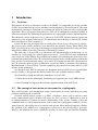
This manual describes an enhanced version of the SPARC V8-compatible and freely available
(LGPL) Leon2 embedded processor, distributed and maintained by Gaisler Research. The main
modifications encompass instruction set extensions for public-key and secret-key cryptographic
algorithms. This Cryptography Instruction Set (CIS) can be configured to include a number of
different instructions for enhancing the performance of cryptographic software implementations.
The enhanced version of the processor is denoted as Leon2-CIS, and this manual explains the
differences to the original Leon2 model. For information about the basic Leon2 model, consult
the Leon2 Processor User’s manual [2].
Leon2-CIS has been developed in the research project Instruction Set Extensions for PublicKey Cryptography (ISEC) which has been funded by the Austrian Science Fund (FWF). The
ISEC project has been carried out at the Institute of Applied Information Processing and Communications (IAIK) of the Graz University of Technology, Austria.
The main idea of Leon2-CIS is to demonstrate the implementation of instructions set extensions for cryptography in a general-purpose processor. Leon2-CIS has been implemented
successfully on various FPGAs and synthesis for standard-cell technology has been tested. Implementation optimization of the CIS extensions have mainly focused on the employed functional
units and the overall instruction timing. As Leon2-CIS is mainly intended for educational use
the CIS extensions have not been optimized for a particular FPGA or standard-cell technology.
Implementation of Leon2-CIS in a specific technology may therefore not make full use of all
features of this technology.
Just like the Leon2, the CIS extensions are distributed under the GNU Lesser General Public
License (LGPL). Consequently the whole Leon2-CIS is also available under the LGPL.
We would like to thank the following contributors to Leon2-CIS:
• Gaisler Research for maintaining, distributing and supporting the Leon2 VHDL model.
• David Canright for supplying his hardware implementation of the AES S-box.
1.2
The concept of instruction set extensions for cryptography
This section explains some fundamental design considerations for secure embedded processing
platforms underlying the Leon2-CIS.
On many modern digital systems (e.g. PDAs, cell phones, smart cards or wireless sensor
nodes) computational power, memory, and energy are scarce resources, which must be used in
an efficient manner to guarantee the desired functionality of the system. Security of data and
communication is a crucial requirement for such systems but cryptographic workloads can be a
great burden for embedded processors found in such systems. The traditional solution to alleviate
this problem is the addition of a cryptographic coprocessor to the general-purpose processor.
However this solution can lead to significant increases in silicon area and often the flexibility
5
of the coprocessor to support different cryptographic algorithms and implementation options is
limited.
An alternative approach is the concept of adding custom instructions to the general-purpose
processor in order to increase its efficiency in processing specific workloads. The custom instructions extend the original instruction set of the processor—hence the term instruction set extension
(ISE). Normally an ISE encompasses instructions which are intended to speed up processing in
a specific application domain. For desktop processors, instruction set extensions for multimedia
(e.g. MMX, SSE) have been very successful. Another application domain is signal processing
as supported by the instructions found in DSPs. The underlying idea of Leon2-CIS is the design
and implementation of instruction set extensions for cryptographic workloads, encompassing
public-key (asymmetric) as well as secret-key (symmetric) algorithms.
Leon2-CIS offers support for most of the important public-key algorithms which perform
modular arithmetic of long integers (e.g. RSA, ECC over prime fields) as well as systems which
require arithmetic in binary extensions fields (e.g. ECC over binary extension fields). For secretkey algorithms, Leon2-CIS has a range of instructions for supporting the Advanced Encryption
Standard (AES).
2
Installation
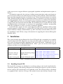
This section describes the installation of the Leon2-CIS model and a customized cross-compiler
system for the Leon2-CIS. After these two steps you will be able to compile the test suite for
the Leon2-CIS and perform HDL simulation of the Leon2-CIS model. Additionally you can
synthesize Leon2-CIS for different FPGA-boards. Table 1 gives an overview of the required
packages and where you can download them.
Name
Description
leon2-1.0.XX-xst.tar.gz Leon2 base package
leon2-cis-1.Y.tar.gz
binutils-2.14.tar.gz
binutils-2.14-cis.patch
Available from
http://www.gaisler.com
http://www.iaik.tugraz.at/isec
Leon2-CIS add-on package http://www.iaik.tugraz.at/isec
GNU binutils
http://www.gnu.org/software/binutils
http://www.iaik.tugraz.at/isec
Leon2-CIS binutils patch
http://www.iaik.tugraz.at/isec
Table 1: Installation packages for Leon2-CIS
2.1
Installing Leon2-CIS
The Leon2-CIS extensions are distributed as an add-on package to the Leon2 from Gaisler Research (base package). This add-on package has been developed in regard to a specific version of
the base package and it should only be used with this version. The add-on package is distributed
as a gzipped tar-file: leon2-cis-1.Y.tar.gz. This archive has the same directory structure as the
6
archive of the base package and it contains modified files of the base package as well as new
files.
The Leon2-CIS model is installed by first installing the respective base package and on top of
that the Leon2-CIS add-on package (replacing existing files). Download the base package and the
add-on package into the directory where you want to install the Leon2-CIS model. The Leon2
base package is assumed to have version 1.0.XX, while the corresponding Leon2-CIS add-on
package is assumed to have version 1.Y. On Unix systems, issue the following commands:
tar xzf leon2-1.0.XX-xst.tar.gz
mv leon2-1.0.XX-xst leon2-cis-1.Y
tar xzf --overwrite leon2-cis-1.Y.tar.gz
# Install base package
# Install add-on package
The Leon2-CIS model is now installed in the leon2-cis-1.Y directory which contains the
same directory structure as the Leon2 base package:
boards
doc
leon
pmon
sim
syn
tbench
tkconfig
tsource
Synthesis packages for FPGA boards
Documentation
Leon2-CIS HDL files
Pmon S-record monitor files
HDL simulation scripts
Synthesis scripts
Testbench HDL files
Graphical model configuration
Source code of test suites
Throughout this manual we will refer to commands in relation to the leon2-cis-1.Y directory,
unless noted otherwise.
2.2
Installing a cross-compiler system for Leon2-CIS
In order to be able to produce executables for the Leon2-CIS, you need to install a cross-compiler
system (GCC, binutils) for SPARC. Gaisler Research offers several cross-compiler systems:
Bare-C cross-compiler (BCC), RTEMS cross-compiler (RTEMS). For producing stand-alone
applications the BCC system should be installed. Refer to the instructions on the Gaisler Research webpage (http://www.gaisler.com) for the corresponding downloads and installation
instructions.
The BCC system from Gaisler Research does of course not recognize the custom instructions
offered by the Leon2-CIS. Therefore it is necessary to use a customized version of the GNU binutils to produce executables for the Leon2-CIS. The customized binutils are based on version 2.14,
available e.g. from the GNU binutils webpage http://www.gnu.org/software/binutils.
Note that the umac and smac instructions of the Leon2 base package are still available in this
modified assembler, but have the different mnemonics of umac16 and smac16 respectively.
7
Download the binutils-2.14.tar.gz package and the patchfile binutils-2.14-cis.patch into the
same directory. You should choose the installation directory (INSTALL DIR) to be the installation directory of the BCC system. In this case the binutils of BCC are replaced by the customized
Leon2-CIS binutils. Issue the following commands to build and install the Leon2-CIS version of
the binutils:
tar xfz binutils-2.14.tar.gz
cd binutils-2.14
patch -p1 ../binutils-2.14-cis.patch
# Apply changes for Leon2-CIS
cd ..
mkdir binutils-build
# Create build dir
cd binutils-build
../binutils-2.14/configure --with-cpu=leon --target=sparc-elf
--prefix=INSTALL_DIR
make
# Build binutils
make install
# Install binutils
This builds the binutils in the binutils-build directory and installs them in INSTALL DIR. After successful installation you can delete the source and build directories (binutils-2.14, binutilsbuild). At last you should add the bin directory of INSTALL DIR to your PATH variable to make
the tools available from any working directory.
3
Leon2-CIS configuration
The Leon2-CIS has several extensions which can be enabled separately. The extensions can
be configured graphically by issuing the command make xconfig in the leon2-cis-1.Y directory. After you have made and saved all changes, issue make dep to generate the configuration files device.vhd (General Leon2 configuration), device.v (Ethernet MAC configuration), and
crypto config.vhd (Leon2-CIS extension configuration). These configuration files are automatically copied into the leon folder, which contains all of the Leon2-CIS HDL files.
The standard configuration options (Synthesis, Clock generation, Processor, AMBA configuration, Memory controller, Peripherals, Boot options, VHDL debugging) are unchanged from
the Leon2 base package and for more information on them, the Leon2 Processor User’s manual
should be consulted. The only difference to Leon2-CIS is that the configuration of hardware multipliers and dividers in the Processor/Integer unit category has been removed. Multiplier/divider
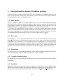
configuration as well as all other configuration regarding the Leon2-CIS extensions is done in the
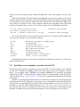
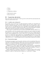
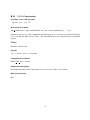
category Leon2-CIS configuration. This category has five sub-categories as shown in Figure 1.
The different configuration categories are described in the following.
3.1
Leon2-CIS version
The version information is intended to help distinguish Leon2-CIS implementations in different
stages of development. There are two different configurable fields. The configured values of
8
Figure 1: Configuration categories for Leon2-CIS extensions
these fields are subsequently available via the read-only crypto configuration register. These
values can be used by software to check for a specific version of the Leon2-CIS. For details on
the crypto configuration register see Section 3.2.2.
It is normally not necessary for you to alter the default values.
3.1.1
Leon2 base version
This option defines a 6-bit unsigned integer value, which should be set to correspond to the used
base version of the Leon2 from Gaisler Research. This means that the value of XX should be set
when the base version leon2-1.0.XX-xst is used.
3.1.2
Leon2-CIS extension version
Irrespective of the base version, this value defines the version of the CIS extensions. Whenever
the Leon2-CIS is revised significantly (e.g. new custom instructions added, implementation of
existing instructions changed), this value should be incremented.
3.2
Auxiliary extensions
The auxiliary extensions are not directly related to cryptographic functionality. They include a
cycle counter and the crypto configuration register.
3.2.1
Cycle counter
If desired, a 32-bit cycle counter can be included in the Leon2-CIS. On a hardware reset of the
processor, the cycle counter is reset to zero and is incremented every clock cycle (irrespective of
pipeline stalls). The cycle counter is implemented as the ancillary state register 19 (%asr19).
9
The cycle counter can be accessed with the wr and rd instructions. To determine the cycle
count for a specific piece of code, there are two principal options. The cycle counter can be read
at the start and at the end of the profiled code segment and the two values subtracted (checking
for a possible overflow of the cycle counter). The second option is to set the cycle counter to
zero at the beginning and to read its value at the end.
If the second option (write-read) is used, the general characteristics of ASR accesses in the
Leon2 as well as the implementation of the cycle counter have to be taken into account. When
a value is written and immediately read back (wr directly followed by rd) and no pipeline stalls
(e.g. due to cache miss) occur, then the read value will be the old value of the cycle counter
before the write. This is due to the implementation of the ASRs of the Leon2, which are read
in the execute stage, but written in the memory stage. Note also that the cycle counter is not
incremented in the cycle in which it is written. As a consequence, the following code produces a
cycle count of 0 (stored in %g1), when no pipeline stalls occur:
wr %g0, %asr19
nop
rd %asr19, %g1
If the rd instruction does not cause a stall of the pipeline (instruction cache miss), then the
read value is the exact number of cycles the execution of the code between write and read of the
cycle counter required minus 1. If two reads of the cycle counter (with overflow checking) are
used, the read value is the exact number of cycles (again assuming no stall for the second read).
Note that if interrupts occur during execution of the profiled code, then the time for executing
the corresponding trap handler is added to the determined cycle count.
If the processor also implements a debug support unit (DSU), %asr19 is mapped to address
0x9008004C. However, it is not possible to access the cycle counter over this address when the
processor is active and software reading from this address will not get the value of the cycle
counter. This address can be used in the debug monitor program (grmon) to access the cycle
counter with the mem and wmem commands.
3.2.2
Crypto configuration register
The crypto configuration register is a read-only register which contains information about the
extensions implemented in the specific instance of the Leon2-CIS. Inclusion of the crypto configuration register can be selected independently. If present, the crypto configuration register is
mapped to the address 0x80000030 and contains the following information:
The possible values for the two overloaded format 3 instructions are given in Table 3 and
Table 4. For details on the functionality of the instructions see Section 3.4.2 and Section 3.4.1
respectively. The possible values for the MAC type are given in Table 5. For a description of the
different multiply-accumulate units refer to Section 3.3.1.
The information in the crypto configuration register can be used by software to check if
required extensions are present in the current version of the Leon2-CIS. It can also be used to
select different functions which use different CIS instructions.
10
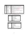
Bits
31:26
25:20
19:18
17:15
Name
Base version
Extension version
UNUSED
FMT3:OP3=0x2D
Definition
Base version of the Leon2-CIS (see Section 3.1.1)
Version of the extensions (see Section 3.1.2)
Constant 0
Implementation of the overloaded format 3 instruction
with op3 = 0x2D (see Section 3.4.2)
14:12 FMT3:OP3=0x2C Implementation of the overloaded format 3 instruction
with op3 = 0x2C (see Section 3.4.2)
11:5 UNUSED
Constant 0
4:2
MAC type
The type of implemented multiply-accumulate unit
(see Section 3.3.1)
1
UNUSED
Constant 0
0
Cycle counter
Indicates that the cycle counter is included as %asr19
(see Section 3.2.1)
Table 2: Crypto configuration register bits
Value (binary)
000
001
010
011
100
101
110
111
Description
No instruction implemented
mulgfs instruction
wra instruction
mixcol instruction
mixcol4 instruction
mixcol4s/imixcol4s instructions
INVALID
INVALID
Table 3: Configuration information for FMT3:OP3=0x2D
Value (binary)
000
001
010
011
100
101
110
111
Description
No instruction implemented
mulgfs2 instruction
rda instruction
sbox instruction
sbox4 instruction
sbox4S/isbox4s/sbox4r instructions
INVALID
INVALID
Table 4: Configuration information for FMT3:OP3=0x2C
11
Value (binary)
000
001
010
011
100
101
110
111
Description
No MAC unit available
Unified MAC available
Unified MAC with AES MixColumns support
INVALID
INVALID
INVALID
INVALID
INVALID
Table 5: Configuration information for MAC type
3.3
Multiplier/divider configuration
This configuration category also contains the standard configuration options of the Leon2 base
package, which were originally available in the Processor/Integer unit category.
3.3.1
Multiplier/MAC unit
If you choose to include one of the multipliers from the Leon2 base package, the multiply instructions umul, umulcc, smul, and smulcc will be available. You can select the latency of
these multiply instructions to be one of 1, 2, 4, 5, or 35. For the 4 cycle latency option—which
includes a (16 × 16)-bit multiplier—you can also enable support for (16 × 16 + 40)-bit multiplyaccumulate instructions. Please note that these ”short” multiply-accumulate instructions have
been renamed to umac16 and smac16, in order for the modified GNU assembler for Leon2-CIS
to work. For more details on these options refer to the Leon2 User’s Manual. Keep in mind that
umac16 and smac16 are referred to as umac and smac in the Leon2 User’s Manual.
Leon2-CIS offers alternate multiplier implementations: The unified multiply-accumulate
units (UNIMAC). The term unified refers to the ability to perform multiplication of integers as
well as of binary polynomials. There are two types of UNIMAC available: UNIMAC 32x16
and UNIMAC 32x16 MIX. Both units include a (32 × 16)-bit multiplier and a 72-bit carrypropagation adder for accumulation. UNIMAC 32x16 MIX also includes support for the AES
MixColumns and InvMixColumns transformations.
Both UNIMAC options enable a range of multiply and multiply-accumulate instructions. The
accumulator (ACCU) is designed as a ”wide” accumulator with a size of 72 bits. This accumulator
is not implemented as a 72-bit register, but is logically formed out of the standard SPARC V8
register %y and two additional ancillary state registers (ASRs): %asr18 and %asr20. These
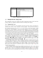
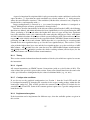
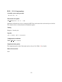
three registers will be denoted as accumulator registers or (ACCU) registers. Figure 2 depicts the
structure of the accumulator.
For the UNIMAC options, the four integer multiply instructions (umul, umulcc, smul, smulcc)
write the lower 32 bits of the multiplication result into the destination register as well as modify
the ICCs (umulcc, smulcc) as described in the SPARC Architecture Manual [5]. In addition,
these instruction write the full multiplication result into the 72-bit accumulator (with sign exten12
31
7 0 31
%asr20
%y
71
Constant 0
0 31
63
0
%asr18
31
0
72-bit accumulator
Figure 2: Structure of the accumulator
sion for signed multiplication).
For both UNIMAC options, the following custom instructions become available:
gf2mul Multiplies two 32-bit binary polynomials and writes lowest 32 bits of the result to the
destination register (rd). The full-length result is written to the accumulator.
gf2mac Multiplies two 32-bit binary polynomials and adds (bitwise XOR) the result to the value
in the accumulator.
shacr Shifts the value in accumulator by 32 bits to the right and puts the shifted out word into
the destination register (rd).
uaddac Adds two 32-bit unsigned integers to the value in the accumulator.
umac2 Multiplies two 32-bit unsigned integers, doubles the result and adds it to the value in the
accumulator.
umac Multiplies two 32-bit unsigned integers and adds the result to the value in the accumulator.
smac Multiplies two 32-bit signed integers and adds the result to the value in the accumulator.
The option UNIMAC 32x16 MIX enables some additional instructions. They all perform
the AES MixColumns or InvMixColumns transformation using the unified multiply-accumulate
unit. The input column is assembled using the first two bytes of the first source register (rs1)
and the last two bytes of the second source register (rs2).
mcmuls Performs AES MixColumns, writing the transformed 32-bit column into the lowest 32
bits of the accumulator. The rest of the accumulator is set to 0.
imcmuls Performs AES InvMixColumns, writing the transformed 32-bit column into the lowest
32 bits of the accumulator. The rest of the accumulator is set to 0.
mcmacs Performs AES MixColumns and adds the transformed 32-bit column (bitwise XOR) to
the value in the accumulator.
imcmacs Performs AES InvMixColumns and adds the transformed 32-bit column (bitwise XOR)
to the value in the accumulator.
13
Instruction
umul
umulcc
smul
smulcc
gf2mul
umac
smac
gf2mac
umac2
mcmuls
imcmuls
mcmacs
imcmacs
shacr
uaddac
Latency
3
3
3
3
3
2 (1)
2 (1)
2 (1)
2 (1)
2 (1)
2 (1)
2 (1)
2 (1)
1
1
Table 6: UNIMAC instruction latencies
The custom instructions enabled by the UNIMAC options have different latencies, i.e. the
number of clock cycles required to produce the result. The latencies are given in Table 6.
Some UNIMAC instructions (umac, smac, gf2mac, umac2, mcmuls, imcmuls, mcmacs, imcmacs)
have a special behavior regarding their latency and are denoted as non-stalling UNIMAC instructions in the following. These instructions only affect the accumulator and do not write to any
standard register in the register file. Non-stalling UNIMAC instructions require two clock cycles
to produce the result. Normally the pipeline of the Leon2 would be stalled until the result is
available but for these instructions the pipeline continues operation. If the subsequent instruction
does not involve one of the accumulator registers and does not use the UNIMAC unit, then it
can be processed in parallel to the UNIMAC instruction (hence the name non-stalling). In that
case the two instructions require two clock cycles, which can be seen as one cycle per instruction. If the following instruction either accesses one of the accumulator registers and/or used
the UNIMAC unit, the pipeline is stalled for one cycle. In that case the non-stalling UNIMAC
instruction requires two clock cycles. In detail, the pipeline stalls if one of these instructions
follows a non-stalling UNIMAC instruction:
• Read (rd, rda) from %asr18, %y or %asr20.
• Write (wr, wra) to %asr18, %y or %asr20.
• SPARC V8 multiply: umul, umulcc, smul, smulcc
• SPARC V8 divide: udiv, udivcc, sdiv, sdivcc
• Instructions involving accumulator: mulscc, mulgfs, mulgfs2, shacr
14
• Instructions using UNIMAC: gf2mul, umac, smac, gf2mac, umac2, mcmuls, imcmuls,
mcmacs, imcmacs, uaddac
3.3.2
SPARC V8 divide instructions
The SPARC V8 divide instructions udiv, udivcc, sdiv, sdivcc can be enabled separately,
which includes a radix-2 divider unit in the Leon2-CIS.
3.3.3
GCC support for multiply and divide instructions
In the Leon2-CIS, support for SPARC V8 multiply and divide instructions can be enabled separately. The GCC compiler emits multiply and divide instructions only if the -mcpu=v8 switch
is set. When compiling C code for the Leon2-CIS you should not set this flag unless both
SPARC V8 multiply and divide instructions are implemented, i.e. the option Multiplier/MAC
unit is not set to none and the SPARC V8 DIV instruction option is set to Y.
3.4
Additional CIS extensions
In this configuration category, additional cryptographic extensions of the Leon2-CIS can be selected. There are two overloaded format 3 instruction opcodes, where a number of different
instructions can be mapped to. This means that depending on the given configuration, the Leon2CIS executes different instructions for the format 3 opcodes 0x2D and 0x2C. These overloaded
instructions encompass light-weight extensions for ECC over binary fields, alternate access instructions for the accumulator (ACCU) registers and instructions to support the AES transformations SubBytes/InvSubBytes and MixColumns/InvMixColumns.
All of the instructions which can be configured have a latency of a single clock cycle.
3.4.1
Overloaded instruction FMT3:OP3=0x2C
The option Instruction on FMT3/OP3 = 0x2C determines, which instruction is implemented on
the format 3 opcode 0x2C. The possible options are listed in the following.
None No instruction is implemented. When a format 3 opcode of 0x2C is encountered, an
invalid instruction trap is generated.
mulgfs2 The mulgfs2 instructions as described in [7] is implemented. It realizes one step in
a multiplication of two binary polynomials, where one execution of mulgfs2 processes a
two bits of the multiplier.
rda The rda instruction is implemented. This instruction can be used to read from the ACCU
registers or from the cycle counter (if implemented). For this instruction the source register
must be one of %accu.lo, %accu.hi, %accu.ex, or %cycnt. This denotes ACCU low word
(bits 31..0), ACCU high word (bits 63..32), ACCU guards bits (bits 71..64), and the cycle
counter respectively.
15
sbox sbox Implements the sbox instruction as described in [8]. This instruction is useful for
realizing the AES SubBytes and InvSubBytes transformations. It requires a register as first
source operand and an immediate value as second source operand, and writes the result to a
destination register: sbox rs1, imm, rd. The value in rs1 is interpreted as four bytes of
the AES State. The immediate value imm selects which substitution is performed (S-box or
inverse S-box). Only a single byte of rs1 is substituted. Which byte this is, is also selected
with imm. The substituted byte replaces one of the four bytes in the destination register
while the other three bytes of rd remain unchanged. The complete definition for the value
of imm is given in Table 7. With four consecutive sbox instructions it is therefore possible
to perform the SubBytes or InvSubBytes operation for a complete AES State column or
row.
sbox4 sbox4 Implements the sbox4 instruction which substitutes all four bytes of the source
register rs1. The result can be byte-wise rotated to the right and is stored in rd. The
second operand must be an immediate value which selects the operation and the rotate
distance (0-3 bytes). The definition for the value of imm is giben in Table 8.
sbox4s Implements three instructions: sbox4s, isbox4s, and sbox4r. The first two require to
source registers and a destination register as operands: sbox4s rs1, rs2, rd, isbox4s
rs1, rs2, rd. Two bytes from rs1 (first and third) and two bytes from rs2 (second and
fourth) are substituted using the AES S-box (sbox4s) or the inverse AES S-box isbox4s
and written into the destination register rd. The sbox4r instruction just has one source
register: sbox4r rs1, rd. All four bytes of rs1 are substituted using the AES S-box and
the result is rotated to the left by one byte before being written into rd. This operation can
be used in implementing the AES key expansion.
Bits
12:9
8
7:6
5:4
Name
UNUSED
Operation
UNUSED
Source byte
Definition
3:2
1:0
UNUSED
Destination byte Selects the destination byte in rd:
00 - most significant byte, 11 least sign. byte
If 1, the S-box is used, otherwise the inverse S-box
Selects the source byte from rs1 for substitution:
00 - most significant byte, 11 least sign. byte
Table 7: Definition of the bits of imm for the sbox instruction
3.4.2
Overloaded instruction FMT3:OP3=0x2D
The option Instruction on FMT3/OP3 = 0x2D determines, which instruction is implemented on
the format 3 opcode 0x2D. The possible options are listed in the following.
16
Bits
12:5
4
3:2
1:0
Name
Definition
UNUSED
Operation
If 1, the S-box is used, otherwise the inverse S-box
UNUSED
Rotation distance The rotation distance (to the right) of the result in bytes:
00 - 0 bytes, 01 - 1 byte, 10 - 2 bytes, 11 - 3 bytes
Table 8: Definition of the bits of imm for the sbox4 instruction
None No instruction is implemented. When a format 3 instruction with the op3 field set to 0x2D
is encountered, an invalid instruction trap is generated.
mulgfs The mulgfs instructions as described in [7] is implemented. It realizes one step in a
multiplication of two binary polynomials, where one execution of mulgfs processes a
single bit of the multiplier.
wra The wra instruction is implemented. This instruction can be used to write to the ACCU registers or to the cycle counter (if implemented). For this instruction the destination register
must be one of %accu.lo, %accu.hi, %accu.ex, or %cycnt. This denotes ACCU low word
(bits 31..0), ACCU high word (bits 63..32), ACCU guards bits (bits 71..64), and the cycle
counter respectively.
mixcol Implements the mixcol instruction. This instruction is useful for realizing the AES MixColumns and InvMixColumns transformations. It requires a register as first source operand
and an immediate value as second source operand, and writes the result to a destination
register: mixcol rs1, imm, rd. The value in rs1 is interpreted as a single AES State
column of 4 bytes, where the most significant byte is the one with the lowest index in the
AES State. The immediate value imm selects which transformation is done (MixColumns
or InvMixColumns). The result of the instruction is a single byte of the resulting AES
State column. Which byte is calculated is also selected with imm. The selected byte in rd
is replaced by the result, while the other three bytes of rd remain unchanged. The complete
definition for the value of imm is given in Table 9. With four consecutive MIXCOL instructions it is therefore possible to perform the MixColumns or InvMixColumns operation for
a complete AES State column.
mixcol4 Implements the mixcol4 instruction. This instruction is very similar to the mixcol
instruction, but it performs the MixColumns of InvMixColumns transformation for all four
bytes in rs1 at the same time: mixcol4 rs1, imm, rd. The value of imm just selects the
operation and the transformed AES State column is written to rd. The definition for imm
if given in Table 10.
mixcol4s With this option selected the two instructions mixcol4s and imixcol4s are implemented. They require always two registers as source operands and write their result to the
destination register mixcol4s/imixcol4s rs1, rs2, rd. Both instructions are mapped
to the same opcode and are made distinguishable for the Leon2-CIS by the assembler
17
through the insertion of different values in the ASI fields of the machine code. As the
instructions’ names imply, mixcol4s performs MixColumns while imixcol4s performs
InvMixColumns. The AES State column to transform is assembled by selecting two bytes
from rs1 (first and second) and two bytes from rs2 (third and fourth). The transformed
AES State column is written to rd.
Bits
12:5
4
3:2
1:0
Name
Definition
UNUSED
Operation
If 1, MixColumns is performed, otherwise InvMixColumns
UNUSED
Destination byte Selects the destination byte in rd:
00 - most significant byte, 11 least sign. byte
Table 9: Definition of the bits of imm for the mixcol instruction
Bits Name
Definition
12:1 UNUSED
0
Operation If 1, MixColumns is performed, otherwise InvMixColumns
Table 10: Definition of the bits of imm for the mixcol4 instruction
3.5
Implementation Options
In this configuration section the implementations of some of the CIS extensions can be selected.
You should not change any of these options unless you know what you are doing!
3.5.1
AES S-box implementation
All custom instructions which perform AES S-box substitution (sbox, sbox4, sbox4s, isbox4s,
sbox4r) use hardware implementations of the AES S-box as functional units. How this S-box is
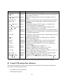
actually implemented can be selected and the options are listed in Table 11.
3.5.2
Unified multiplier: Propagation adder type
The unified multiplier used by the UNIMAC units contains a 53-bit carry propagation adder
composed of dual-field adder cells ([3]). This adder can be selected to be implemented either
as a ripple-carry adder or a square-root carry-select adder. For the latter option, the number of
stages (up to 20) and the size of these stages can be configured.
When configuring the square-root carry-select adder, you must first set the number of stages.
Assuming that you configured the adder to have N stages, you must then select the size of each
stage. Starting from stage 0 (which processes the least significant bits) enter the size (in bits) of
each stage up to stage N-1. The total size of all stages (from 0 to N-1) must be equal to 53 in
order to ensure a correct configuration.
18
Option
Wolkerstorfer
Description
Implementation following the approach by
Wolkerstorfer et al. [10]
Canright
Implementation following the approach by
Canright [1]
Hardware-LUT Hardware look-up table of S-box and inverse S-box.
Not optimized for synthesis!
Hybrid-LUT
Hardware look-up table of GF(28 ) inversion, where
affine and inverse affine transformation are calculated.
Not optimized for synthesis!
Table 11: AES S-box implementation options
3.5.3
Unified MAC: Propagation adder type
The unified MAC (UNIMAC) contains a 72-bit carry propagation adder, which can be configured
in the same fashion as the one in the unified multiplier. Refer to Section 3.5.2 for details. The
only difference is that the total size of all stages must be equal to 72.
4
Implementation details of the CIS extensions
Most of the Leon2-CIS extensions rely on customized functional units (FUs) which have been
added to the execute stage of the Leon2 pipeline. Most functionality for the public-key extensions
is realized in a so-called unified multiply-accumulate (UNIMAC) unit. For most of the secretkey extensions, dedicated functional units are used. These custom functional units are described
in the following sections.
4.1
Modified ripple-carry adder
For the multiply-step instruction for binary polynomials mulgfs2, a modified ripple-carry adder
with carry insertion as proposed in [7] is included.
4.2
Unified multiply-accumulate unit
All multiply and multiply-accumulate instructions for both integers and binary polynomials
(umul, umulcc, smul, smulcc, umac, smac, umac2, gf2mul, gf2mac) are realized with a unified multiply-accumulate unit (UNIMAC) whose design is based on the concept presented in
[4]. Also the uaddac instruction is realized in the UNIMAC. The UNIMAC unit includes a unified (32 × 16)-bit multiplier and a 32-bit carry-propagation adder (for uaddac), a 50-bit pipeline
register, a 72-bit unified adder and an equally long accumulator register for intermediate values.
An extended version of the UNIMAC unit also supports AES MixColumns and InvMixColumns with an optional subsequent AddRoundKey functionality (aka accumulation using
19
XOR). This unit is denoted as UNIMAC MIX and used to implement the following instructions:
mcmuls, imcmuls, mcmacs, and imcmacs.
4.3
AES S-box unit
For instructions which perform substitution using the AES S-box and inverse S-box, a hardware
implementation of the AES S-box is used. There are different hardware implementations available for selection (refer to Section 3.5.1 for details). Depending on the included extensions, one
(sbox) or four (sbox4, sbox4s/isbox4s/sbox4r) of the AES S-box units are integrated into
the Leon2-CIS.
4.4
AES MixColumns unit
Some of the instructions for AES MixColumns and InvMixColumns rely on a dedicated functional unit. This FU is based on the concept presented in [9]. For mixcol only a single
MixColumn-multiplier is included while mixcol4 and mixcol4s/imixcol4s instructions require four MixColumns-multipliers.
5
Software development for the Leon2-CIS
5.1
Using the CIS custom instructions
The Leon2-CIS custom instructions can be used either with the inline assembly construct within
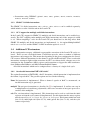
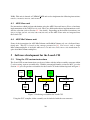
C code or using separate assembly files. With the customized binutils version for BCC (see also
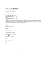
Section 2.2) you can produce executables for the Leon2-CIS in the fashion depicted in Figure 3.
C code
C code
with inline
ASM
Custom
ASM
functions
sparc-elf-gcc -S
sparc-elf-as
sparc-elf-ld
Generated
ASM
Object
files
Executable
Figure 3: Producing executables for Leon2-CIS
Using the GCC compiler, inline assembly can be included with the asm construct:
20
asm ( assembler template
: output operands
: input operands
: list of clobbered registers
);
/* optional */
/* optional */
/* optional */
For more details refer to the corresponding GCC manual [6]. For writing assembly files
you can use the template file tsource/unimac ASM FUNCT TEMPLATE.S. Refer to the inline
documentation of this file for usage instructions. Note that .S files require preprocessing before
they can be assembled to object code.
A small example package (cis sw example.tar.gz) demonstrating the use of custom instructions can be downloaded from the ISEC web page at http://www.iaik.tugraz.at/isec.
5.2
Cryptographic reference implementations
Cryptographic software for the Leon2-CIS is available on the ISEC web page (http://www.
iaik.tugraz.at/isec).
6
Simulation
All simulation scripts of the Leon2 base package have been adapted to include the new HDL files
of the Leon2-CIS. Simulation of the Leon2-CIS has been successfully performed with Modelsim
as well as Cadence ncsim. Compilation for the GNU VHDL simulator (version 0.21) failed
with some errors. Refer to the Leon2-CIS release notes (Leon2-CIS RELEASE NOTES.txt) for
details. Simulation with Synopsys VSS has not been tested.
The Leon2-CIS package includes two test suites: The standard test suite from the Leon2 base
package and a suite which checks the functionality of the CIS extensions. Each test suite can
be compiled to a RAM image, which is subsequently executed by the Leon2-CIS simulated by
a HDL simulator. In order to build the test suites, you need a working installation of the BCC
systems with the modified binutils as described in Section 2.2.
The standard test suite can be built from the Leon2-CIS top level directory (leon2-cis-1.Y)
with make tsoft. For building the CIS test suite change into the tsource directory and issue the
command make unimac ram. For details on simulation refer to the Leon2 User’s Manual [2].
The CIS test suite checks the crypto configuration register to select the tests for the implemented extensions. Therefore it is important to include the crypto configuration register to ensure
correct functionality of the CIS test suite. See Section 3.2.2 for details on the crypto configuration register. The CIS test suite is divided into different test categories. The success or failure of
each test is reported separately. The output should look like this:
*** Starting LEON system test ***
UNIMAC simple functionality tests
21
---------------------------------------Test 0 OK
...
Test 0x80f OK
MULGFS functionality tests
---------------------------------------UNIMAC alternative ACC instructions
---------------------------------------UNIMAC advanced functionality tests
---------------------------------------Test 0 OK ... Test 0x609 OK
UNIMAC trap behavior tests
---------------------------------------Test 0 OK
...
Test 0x101 OK
AES SBOX & MIXCOL functionality tests
---------------------------------------Test 0x1200 OK
...
Test 0x2300 OK
Test completed OK, halting with failure
ASSERT/FAILURE (time 1048842 NS) from process :tb:testmod0:rep
(architecture WORK.testmod:behav)
TEST COMPLETED OK, ending with FAILURE
7
Synthesis
The synthesis scripts in the syn directory have been adapted to include the new HDL files from
Leon2-CIS. However most of the scripts have not been tested.
The files for FPGA-board synthesis (directory boards) have also been adapted. Tests have
been carried out for most of the boards. For details on changed files and untested boards, refer to
22
the Leon2-CIS release notes (Leon2-CIS RELEASE NOTES.txt). The test suite for Leon2-CIS
for simulation can also be compiled as a stand-alone executable for execution on an FPGA board.
This can be done by issuing the command make unimac exe within the tsource directory. The
resulting executable is unimac leon test HW.exe.
23
A
Description of the Leon2-CIS add-on package
As the Leon2 base package and the Leon2-CIS add-on package are distributed separately, the
changed and added files are obvious. The following sections describe the most important modified and added files of the Leon2-CIS package.
A.1
HDL model
Table 12 contains all HDL files (within subdirectory leon) of the Leon2-CIS add-on package
which have been modified or added with respect to the Leon2 base package. In addition to the
cryptographic extensions, the Opencores Ethernet MAC included in the Leon2 has also been
updated to the newest version available (at the time of writing) in the Leon2-CIS.
In almost all modified HDL files the changes are contained within BEGIN MODIFICATION
<NAME> and END MODIFICATION <NAME> comments, where <NAME> is normally CIS. Code outside of these comment pairs is unchanged from the Leon2 base package. The only exceptions
are the automatically generated files device.v and device.vhd as well as eth top.v.
A.2
Test suite
The subdirectory tsource contains all files of the test suite for the Leon2-CIS (files prefixed by
unimac ). The test suite is divided into several sets of test cases, where each of these sets consists
of three files: A C source file (.c), a C header file (.h) and an assembly file (.S). Testing is done by
executing test functions (written in assembly) which test specific CIS custom instructions. The
C source file calls the test functions and keeps track of errors. The C header file contains the
signature of the test functions. The assembly file contains the definition of the test functions.
A.3
Simulation
The subdirectory tbench contains modified files of the VHDL testbench which the subdirectory
sim contains adapted scripts for HDL compilation for various simulators.
A.4
Graphical configuration
The subdirectory tkconfig contains the modified files necessary to configure the Leon2-CIS model
graphically.
A.5
Synthesis
Within the subdirectory syn, synthesis scripts adapted to Leon2-CIS are contained. The boards
subdirectory contains modified files which are required for synthesis for specific FPGA boards.
Details can be found in the Leon2-CIS release notes (Leon2-CIS RELEASE NOTES.txt).
24
File
addlib.vhd
aes lib.vhd
Status
Added
Added
aes sbox canright.vhd Added
ambacomp.vhd
apbmst.vhd
Modified
Modified
crypto config.vhd
Added
crypto config reg.vhd Added
debug.vhd
device.v
Modified
Modified
device.vhd
Modified
eth top.v
Modified
iface.vhd
iu.vhd
lconf.vhd
Modified
Modified
Modified
mac.vhd
maclib.vhd
Added
Added
mcore.vhd
Modified
sparcv8.vhd
unimac mix.vhd
unimul mix 32x16
Modified
Added
Added
Description
Modified ripple-carry adder (see Section 4.1).
AES S-box and MixColumns/InvMixColumns implementations.
See Sections 4.3 and 4.4.
AES S-box implementation by David Canright translated to
VHDL.
Component declaration for crypto configuration register added.
Mapping of crypto configuration register to memory address
0x80000030.
Configuration options for CIS extensions. Automatically
generated by graphical configuration.
Crypto configuration register indicating the implemented
extensions. See Section 3.2.2 for details.
Support for CIS custom instructions for disassembler included.
Configuration of Leon2 ethernet MAC. Automatically generated
by graphical configuration.
Configuration of Leon2 base package. Automatically generated
by graphical configuration.
Contains the latest (at time of writing) Opencores Ethernet
MAC by Igor Mohor et al.
Declarations for UNIMAC units’ in and out signals added.
Integration of all CIS extensions into processor pipeline.
Conditions for UMUL/SMUL bits of Leon2 configuration
register adapted.
Contains UNIMAC unit (see Section 4.2).
Entities for UNIMAC units: Unified (32 × 16)-bit
multiplier, unified adders with generic width.
Crypto configuration register included as APB slave device at
index 14. Note: Index 15 remains unused.
Constant definitions for custom instruction decoding added.
Contains UNIMAC MIX unit (see Section 4.2).
Unified (32 × 16)-bit multiplier required by UNIMAC MIX
unit.
Table 12: Modified/added HDL files of Leon2-CIS in regard to the Leon2 base package
B
Leon2-CIS instruction reference
This appendix describes the CIS custom instructions in full detail. For each instruction information is given in the following sections:
• Assembly syntax and operands.
• Functional description.
25
• Timing.
• Opcode.
• Configuration conditions.
• Implementation options.
• Related instructions.
B.1
Organization and notation
This section outlines the information, which is given for each Leon2-CIS custom instruction and
defines the notation which is used.
B.1.1
Assembly syntax and operands
The assembly syntax describes the usage of the instruction in assembly code. All possible combinations of operand types is given. Usually instructions have two source operands. One of
the source operands is normally a register (rs1) while the other source operand can be either a
register (rs2) or a 13-bit immediate value (imm). Depending on the instruction, this immediate
value can be sign-extended to a length of 32 bits before it is used in the instruction’s operation.
Normally the result of the instruction is written into a destination register (rd).
The %y register is specified in the usual convention of the SPARC Architecture Manual as %y.
Some instructions access the accumulator registers and the cycle counter explicitly and require
the syntax %accu.X for accessing a word of the accumulator and %cycnt to denote the cycle
counter. For the accumulator %accu.X can be either %accu.lo for the lowest 32 bits (bits 0 to
31), %accu.hi for the bits 32 to 63, and %accu.ex for the highest 8 bits (bits 64 to 71). Note
that %accu.ex denotes the eight guard bits of the accumulator. Reading %accu.ex delivers the
eight guard bits as the lowest eight bits of the result while all other bits are zero. When writing a
32-bit value to %accu.ex, only the eight lowest bits are written while all other bits are discarded.
B.1.2
Functional description
The functional description is given in a pseudo-code form as well as in textual form. The pseudocode form uses the following notation. The first and second source operand of the instruction are
denoted as src1 and src2 respectively. The second source operand can either correspond to a
register or to an immediate value. The destination register is denoted as dst.
SIGNEXT(src2) is used to express that the operand is sign-extended if it is an immediate
value. If it is an register, then SIGNEXT does nothing. ICCs denotes the integer condition codes
which are contained in the processor state register (%ps). The 72-bit accumulator is denoted as
ACCU. The 32 least significant bits of a longer value are selected with .LO.
Bitwise logical and, or, exclusive or and inversion is denoted by AND, OR, XOR, and NOT
respectively. A shift to the left by X bits is denoted as << X, a shift to the right as >> X (no sign
extension). A rotate of a 32-bit value by X is denoted <<< X (left) and >>> X (right).
26
A part of a functional description which is only present under certain conditions is enclosed in
square brackets: []. Operation on certain conditions are selected with an IF () ELSE construct,
where the round brackets contain a C-like condition (if 0 then false, otherwise true). Equality is
checked with == and inequality with !=.
Integer multiplication is denoted by * (see textual description whether it is unsigned or
signed). Multiplication of binary polynomials is denoted with ⊗.
In order to describe functionality of the Advanced Encryption Standard (AES), the following
functions are defined: AES SBOX substitutes the least significant byte of its operand using the AES
S-box, producing a 32-bit result where the higher three bytes are zero and the least significant
byte is the substituted value. AES ISBOX does the same using the AES inverse S-box. AES SBOX4
and AES ISBOX4 substitute all four bytes of their operand using the AES S-box and inverse S-box
respectively. AES MIXCOL transforms its first operand with the AES MixColumns transformation,
producing one byte of the result column. Which byte this is is specified by its second operand
(from 0 for the most significant byte up to 3 for the least significant byte). The result is a 32-bit
value with the higher three bytes zero and the least significant byte set to the result byte of AES
MixColumns. AES IMIXCOL does the same but uses the AES InvMixColumns transformation.
AES MIXCOL4 and AES IMIXCOL4 produce the whole resulting column (all four bytes) for the
AES MixColumns and InvMixColumns transformations.
B.1.3
Timing
This section contains information about the number of clock cycles which are required to execute
the instruction.
B.1.4
Opcode
All custom instructions are SPARC format 3 instructions (with an op field value of 0x2). The
value of the 6-bit op3 field is given in this section. Some related instructions have the same value
of the op3 field and are distinguished by the value of additional fields (e.g. rd, ASI).
B.1.5
Configuration conditions
If you do not use the graphical configuration (see Section 3, then the Leon2-CIS model can
be configured manually by changing the constants in the crypto config package within the file
leon/crypto config.vhd. This section specifies the constant values required to include the instruction in the Leon2-CIS. Some of the constant options require also a specific configuration in
leon/device.vhd.
B.1.6
Implementation options
If the instruction can be implemented in different ways, then the available options are given in
this section.
27
B.1.7
Related instructions
This section outlines similarities to other instructions defined in the SPARC Architecture Manual
or in the original Leon2.
28
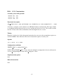
B.2
UMUL instruction
Assembly syntax and operands
umul rs1, rs2, rd
umul rs1, imm, rd
umul imm, rs1, rd
Functional description
.LO(src1 * SIGNEXT(src2)) → dst
src1 * SIGNEXT(src2) → ACCU
Performs unsigned multiplication of the first and second source operand. The lowest 32 bits
of the result are written into the destination register. The full-length result is written into the
accumulator.
Timing
Requires 3 clock cycles.
Opcode
op3 == 0x0A
Configuration conditions
CRYPTO MAC == mac32x16 OR
CRYPTO MAC == unimac32x16 mix
NOTE: When CRYPTO MAC != none, then the multiplier configuration in device.vhd must be
set to iu config.multiplier = none and iu config.mac = false.
Implementation options
This instruction can be realized either with the UNIMAC unit or with the UNIMAC MIX unit.
Related instructions
This instructions encompasses the functionality described in the SPARC Architecture Manual,
with the addition that the result is written into the ACCU.
29
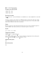
B.3
UMULcc instruction
Assembly syntax and operands
umulcc rs1, rs2, rd
umulcc rs1, imm, rd
umulcc imm, rs1, rd
Functional description
.LO(src1 * SIGNEXT(src2)) → dst
src1 * SIGNEXT(src2) → ACCU
ICCs in
Performs unsigned multiplication of the first and second source operand. The lowest 32 bits
of the result are written into the destination register. The full-length result is written into the
accumulator. The integer condition codes (ICCs) are updated according to the specification for
umulcc in the SPARC Architecture Manual.
Timing
Requires 3 clock cycles.
Opcode
op3 == 0x1A
Configuration conditions
CRYPTO MAC == mac32x16 OR
CRYPTO MAC == unimac32x16 mix
NOTE: When CRYPTO MAC != none, then the multiplier configuration in device.vhd must be
set to iu config.multiplier = none and iu config.mac = false.
Implementation options
This instruction can be realized either with the UNIMAC unit or with the UNIMAC MIX unit.
Related instructions
This instructions encompasses the functionality described in the SPARC Architecture Manual,
with the addition that the result is written into the ACCU.
30
B.4
SMUL instruction
Assembly syntax and operands
smul rs1, rs2, rd
smul rs1, imm, rd
smul imm, rs1, rd
Functional description
.LO(src1 * SIGNEXT(src2)) → dst
src1 * SIGNEXT(src2) → ACCU
Performs signed multiplication of the first and second source operand. The lowest 32 bits of
the result are written into the destination register. The full-length multiplication result is signextended to 72 bits and written into the accumulator.
Timing
Requires 3 clock cycles.
Opcode
op3 == 0x0B
Configuration conditions
CRYPTO MAC == mac32x16 OR
CRYPTO MAC == unimac32x16 mix
NOTE: When CRYPTO MAC != none, then the multiplier configuration in device.vhd must be
set to iu config.multiplier = none and iu config.mac = false.
Implementation options
This instruction can be realized either with the UNIMAC unit or with the UNIMAC MIX unit.
Related instructions
This instructions encompasses the functionality described in the SPARC Architecture Manual,
with the addition that the result is written into the ACCU.
31
B.5
SMULcc instruction
Assembly syntax and operands
smulcc rs1, rs2, rd
smulcc rs1, imm, rd
smulcc imm, rs1, rd
Functional description
.LO(src1 * SIGNEXT(src2)) → dst
src1 * SIGNEXT(src2) → ACCU
ICCs in
Performs signed multiplication of the first and second source operand. The lowest 32 bits of the
result are written into the destination register. The full-length result is written into the accumulator. The integer condition codes (ICCs) are updated according to the specification for smulcc
in the SPARC Architecture Manual.
Timing
Requires 3 clock cycles.
Opcode
op3 == 0x1A
Configuration conditions
CRYPTO MAC == mac32x16 OR
CRYPTO MAC == unimac32x16 mix
NOTE: When CRYPTO MAC != none, then the multiplier configuration in device.vhd must be
set to iu config.multiplier = none and iu config.mac = false.
Implementation options
This instruction can be realized either with the UNIMAC unit or with the UNIMAC MIX unit.
Related instructions
This instructions encompasses the functionality described in the SPARC Architecture Manual,
with the addition that the result is written into the ACCU.
32
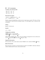
B.6
UMAC instruction
Assembly syntax and operands
umac rs1, rs2
umac rs1, imm
umac imm, rs1
Functional description
src1 * SIGNEXT(src2) + ACCU → ACCU
Performs unsigned multiplication of the first and second source operand. The result is added to
the value in the accumulator.
Timing
Requires 1 clock cycle, if the subsequent instruction does not access the accumulator registers or
use the UNIMAC unit. Otherwise the umac instruction requires 2 clock cycles.
Opcode
op3 == 0x19, rd == 0x07
Configuration conditions
CRYPTO MAC == mac32x16 OR
CRYPTO MAC == unimac32x16 mix
NOTE: When CRYPTO MAC != none, then the multiplier configuration in device.vhd must be
set to iu config.multiplier = none and iu config.mac = false.
Implementation options
This instruction can be realized either with the UNIMAC unit or with the UNIMAC MIX unit.
Related instructions
The Leon2 base package also includes a similar instruction which performs a (16 × 16)-bit multiplication and addition to a 40-bit accumulator. Using the assembler modified for Leon2-CIS,
this ”short” unsigned multiply-accumulate has the mnemonic umac16.
33
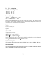
B.7
SMAC instruction
Assembly syntax and operands
smac rs1, rs2
smac rs1, imm
smac imm, rs1
Functional description
src1 * SIGNEXT(src2) + ACCU → ACCU
Performs signed multiplication of the first and second source operand. The result is added to the
value in the accumulator.
Timing
Requires 1 clock cycle, if the subsequent instruction does not access the accumulator registers or
use the UNIMAC unit. Otherwise the smac instruction requires 2 clock cycles.
Opcode
op3 == 0x19, rd == 0x08
Configuration conditions
CRYPTO MAC == mac32x16 OR
CRYPTO MAC == unimac32x16 mix
NOTE: When CRYPTO MAC != none, then the multiplier configuration in device.vhd must be
set to iu config.multiplier = none and iu config.mac = false.
Implementation options
This instruction can be realized either with the UNIMAC unit or with the UNIMAC MIX unit.
Related instructions
The Leon2 base package also includes a similar instruction which performs a (16 × 16)-bit multiplication and addition to a 40-bit accumulator. Using the assembler modified for Leon2-CIS,
this ”short” signed multiply-accumulate has the mnemonic smac16.
34
B.8
WRA instruction
Assembly syntax and operands
wra
wra
wra
wra
rs1,
rs1,
rs1,
imm,
rs2, %accu.X/cycnt
imm, %accu.X/cycnt
%accu.X/cycnt
%accu.X/cycnt
The %accu.X notation is used to access one of the accumulator registers: %accu.lo for the
lowest 32 bits, %accu.hi for the bits 32 to 63, and%accu.ex for the highest 8 bits. Is is also
possible to access the cycle counter with the notation %cycnt.
Functional description
src1 [XOR SIGNEXT(src2)] → %accu.X/cycnt
Writes to one of the accumulator registers or to the cycle counter. If the instruction has only one
source operand, its value is written. If the instructions has two source operands, the written value
is the bitwise XOR of the values of the first and second source operand. If the second operand is
an immediate value, it is sign-extended prior to the XOR.
When the destination register is not implemented, an illegal instruction trap is generated.
Timing
Requires 1 clock cycle.
Opcode
op3 == 0x2C
Configuration conditions
In order for the wra instruction to be available, it is required to configure one of the overloaded
opcodes (op3 == 0x2C) accordingly:
FMT3 OP3 2C == wra
Additionally the accumulator and the cycle counter must be implemented:
CRYPTO MAC != none (for access to %accu.X)
CYCLCNT EN == true (for access to %cycnt)
NOTE: When CRYPTO MAC != none, then the multiplier configuration in device.vhd must be
set to iu config.multiplier = none and iu config.mac = false.
Implementation options
N/A
35
Related instructions
The wra instruction behaves just like the SPARC V8 wry and wrasr instruction, with the difference that wra only allows writing to the accumulator and the cycle counter.
36
B.9
RDA instruction
Assembly syntax and operands
rda %accu.X/cycnt, rd
The %accu.X notation is used to access one of the accumulator registers: %accu.lo for the
lowest 32 bits, %accu.hi for the bits 32 to 63, and%accu.ex for the highest 8 bits. Is is also
possible to access the cycle counter with the notation %cycnt.
Functional description
%accu.X/cycnt → dst
Reads from one of the accumulator registers or from the cycle counter. The read value is written
into the destination register.
When the source register is not implemented, the result of the rda instruction is undefined.
However, no illegal instruction trap is generated.
Timing
Requires 1 clock cycle.
Opcode
op3 == 0x2D
Configuration conditions
In order for the rda instruction to be available, it is required to configure one of the overloaded
opcodes (op3 == 0x2D) accordingly:
FMT3 OP3 2D == rda
Additionally the accumulator and the cycle counter must be implemented:
CRYPTO MAC != none (for access to %accu.X)
CYCLCNT EN == true (for access to %cycnt)
NOTE: When CRYPTO MAC != none, then the multiplier configuration in device.vhd must be
set to iu config.multiplier = none and iu config.mac = false.
Implementation options
N/A
37
Related instructions
The rda instruction behaves just like the SPARC V8 rdy and rdasr instruction, with the difference that rda only allows reading from the accumulator and the cycle counter.
38
B.10
MULGFS instruction
Assembly syntax and operands
mulgfs rs1, rs2, rd
mulgfs rs1, imm, rd
Functional description
(src1 >> 1) XOR (src2 * (%y AND 0x1)) → dst
((src1 AND 0x1) << 31) OR (%y >> 1) → %y
Performs a multiply-step instructions for binary polynomials, where 1 bit of the multiplier is
processed. In detail, the following steps are performed:
1. The value in the first source register (src1) is shifted right by one. The shifted value is
denoted as C.
2. If he least significant bit of %y is one, a partial product (denoted as A) is set to the value of
the multiplicand (src2). Otherwise A is zero. If (src2) is an immediate value, then it is
not sign-extended.
3. The contents of the %y register is shifted right by one with the least significant bit of src1
shifted in from the left. The bit of the multiplier, which has been processed in the previous
step, is therefore shifted out of %y.
4. A bitwise XOR of A and C is performed and the result is stored in the destination register
(dst).
Note that an immediate value as second source operand is not sign-extended.
Timing
Requires 1 clock cycle.
Opcode
op3 == 0x2C
Configuration conditions
FMT3 OP3 2C == mulgfs
Implementation options
N/A
39
Related instructions
The mulgfs instruction behaves similar to the SPARC V8 mulscc instruction. The main difference is that mulgfs operates on binary polynomials instead of integers. Other differences are
that mulgfs does not modify the ICCs and that immediate operands are not sign-extended.
40
B.11
MULGFS2 instruction
Assembly syntax and operands
mulgfs2 rs1, rs2, rd
mulgfs2 rs1, imm, rd
Functional description
(src1 >> 2) XOR ((src2 >> 1) * (%y AND 0x1)) XOR (src2 * ((%y >> 1) AND 0x1))
→ dst
((((src1 >> 1) AND 0x1) XOR ((src2 AND 0x1) AND ((%y >> 1) AND 0x1))) << 31)
OR ((src1 AND 0x1) << 30) OR (%y >> 2) → %y
Performs a multiply-step instructions for binary polynomials, where 2 bits of the multiplier are
processed. In detail, the following steps are performed:
1. The value in the first source register (src1) is shifted right by two. The shifted value is
denoted as C.
2. If the least significant bit of %y is one, a partial product (denoted as B) is set to the value
of the multiplicand (src2) shifted right by one. Otherwise B is zero. If (src2) is an
immediate value, then it is not sign-extended.
3. If the second lowest bit of %y is is one, a second partial product (denoted as A) is set to the
value of the multiplicand (src2). Otherwise A is zero. If (src2) is an immediate value,
then it is not sign-extended.
4. The contents of the %y register is shifted right by two with the following bits set as the new
most significant bits: The one but highest bit is set to the value of the least significant bit
of src1. The highest bit results from an XOR of the second lowest bit of src1 and the
logical AND of the least significant bit of the multiplicand (src2) and the second lowest
bit of %y.
5. A bitwise XOR of A, B and C is performed and the result is stored in in the destination
register (dst).
Note that an immediate value as second source operand is not sign-extended.
Timing
Requires 1 clock cycle.
Opcode
op3 == 0x2D
41
Configuration conditions
FMT3 OP3 2D == mulgfs2
Implementation options
N/A
Related instructions
The mulgfs2 instruction performs the work of two subsequent mulgfs instructions with the
same operands.
42
B.12
GF2MUL instruction
Assembly syntax and operands
gf2mul rs1, rs2, rd
gf2mul rs1, imm, rd
gf2mul imm, rs1, rd
Functional description
.LO(src1 ⊗ SIGNEXT(src2)) → dst
src1 ⊗ SIGNEXT(src2) → ACCU
Performs multiplication of the first and second source operand interpreting them as binary polynomials. The lowest 32 bits of the result are written into the destination register. The full-length
result is written into the accumulator.
Timing
Requires 3 clock cycles.
Opcode
op3 == 0x09
Configuration conditions
CRYPTO MAC == mac32x16 OR
CRYPTO MAC == unimac32x16 mix
NOTE: When CRYPTO MAC != none, then the multiplier configuration in device.vhd must be
set to iu config.multiplier = none and iu config.mac = false.
Implementation options
This instruction can be realized either with the UNIMAC unit or with the UNIMAC MIX unit.
Related instructions
This instructions behaves like the CIS umul instruction, but does interpret the source operands
as binary polynomials and not as integers.
43
B.13
GF2MAC instruction
Assembly syntax and operands
gf2mac rs1, rs2
gf2mac rs1, imm
gf2mac imm, rs1
Functional description
(src1 ⊗ SIGNEXT(src2)) XOR ACCU → ACCU
Performs multiplication of the first and second source operand, interpreting them as binary polynomials. The result is added (bitwise XOR) to the value in the accumulator.
Timing
Requires 1 clock cycle, if the subsequent instruction does not access the accumulator registers or
use the UNIMAC unit. Otherwise the gf2mac instruction requires 2 clock cycles.
Opcode
op3 == 0x19, rd == 0x04
Configuration conditions
CRYPTO MAC == mac32x16 OR
CRYPTO MAC == unimac32x16 mix
NOTE: When CRYPTO MAC != none, then the multiplier configuration in device.vhd must be
set to iu config.multiplier = none and iu config.mac = false.
Implementation options
This instruction can be realized either with the UNIMAC unit or with the UNIMAC MIX unit.
Related instructions
This instructions behaves like the CIS umac instruction, but does interpret the source operands
as binary polynomials and not as integers.
44
B.14
SHACR instruction
Assembly syntax and operands
shacr rd
Functional description
.LO(ACCU) → dst
ACCU >> 32 → ACCU
Shifts the accumulator 32 bits to the right (shifting in 0 from the left). The shifted out bits are
written into the destination register.
Timing
Requires 1 clock cycle.
Opcode
op3 == 0x1D
Configuration conditions
CRYPTO MAC == mac32x16 OR
CRYPTO MAC == unimac32x16 mix
NOTE: When CRYPTO MAC != none, then the multiplier configuration in device.vhd must be
set to iu config.multiplier = none and iu config.mac = false.
Implementation options
N/A
Related instructions
N/A
45
B.15
UMAC2 instruction
Assembly syntax and operands
umac2 rs1, rs2
umac2 rs1, imm
umac2 imm, rs1
Functional description
((src1 * SIGNEXT(src2)) * 2) + ACCU → ACCU
Performs unsigned multiplication of the first and second source operand. The result is doubled
and subsequently added to the value in the accumulator.
Timing
Requires 1 clock cycle, if the subsequent instruction does not access the accumulator registers or
use the UNIMAC unit. Otherwise the umac2 instruction requires 2 clock cycles.
Opcode
op3 == 0x19, rd == 0x06
Configuration conditions
CRYPTO MAC == mac32x16 OR
CRYPTO MAC == unimac32x16 mix
NOTE: When CRYPTO MAC != none, then the multiplier configuration in device.vhd must be
set to iu config.multiplier = none and iu config.mac = false.
Implementation options
This instruction can be realized either with the UNIMAC unit or with the UNIMAC MIX unit.
Related instructions
This instructions behaves like the CIS umac instruction, with the only difference of the doubling
of the multiplication result prior to accumulation.
46
B.16
UADDAC instruction
Assembly syntax and operands
uaddac rs1, rs2
uaddac rs1, imm
uaddac imm, rs1
Functional description
src1 + SIGNEXT(src2) + ACCU → ACCU
Interprets the two source operands as unsigned integers and adds them to the value in the accumulator.
Timing
Requires 1 clock cycle.
Opcode
op3 == 0x19, rd == 0x05
Configuration conditions
CRYPTO MAC == mac32x16 OR
CRYPTO MAC == unimac32x16 mix
NOTE: When CRYPTO MAC != none, then the multiplier configuration in device.vhd must be
set to iu config.multiplier = none and iu config.mac = false.
Implementation options
This instruction can be realized either with the UNIMAC unit or with the UNIMAC MIX unit.
Related instructions
N/A
47
B.17
SBOX instruction
Assembly syntax and operands
sbox rs1, imm, rd
Functional description
IF (((imm >> 8) AND 0x1) == 1)
(AES SBOX((src1 >> (((src2 >> 4) AND 0x3) * 8)) AND 0xFF) << ((src2 AND 0x3)
* 8)) OR (dst AND NOT(0xFF << ((src2 AND 0x3) * 8))) → dst
ELSE
(AES ISBOX((src1 >> (((src2 >> 4) AND 0x3) * 8)) AND 0xFF) << ((src2 AND 0x3)
* 8)) OR (dst AND NOT(0xFF << ((src2 AND 0x3) * 8))) → dst
Selects one byte of src1 (depending on src2), performs substitutions using the AES S-box or
inverse S-box (depending on src2) and replaces a byte of the destination register. The replaced
byte is selected by the value of src2. The other three bytes of the destination register remain
unchanged. For the value definition of the second source operand refer to Table 7.
Timing
Requires 1 clock cycle. Note that a loadlock of the pipeline can also occur for the destination
register dst with this instruction.
Opcode
op3 == 0x2D
Configuration conditions
FMT3 OP3 2D == sbox
Implementation options
The implementation of the S-box unit can be selected. See Table 11 for details.
Related instructions
N/A
48
B.18
SBOX4 instruction
Assembly syntax and operands
sbox4 rs1, imm, rd
Functional description
IF (((imm >> 4) AND 0x1) == 1)
AES SBOX4(src1) >>> ((src2 AND 0x3) * 8) → dst
ELSE
AES ISBOX4(src1) >>> ((src2 AND 0x3) * 8) → dst
Substitute all four bytes of the first source operand using the AES S-box or inverse S-box (depending on src2). The substituted value is rotated to the right by a distance of either 0, 1, 2, or
3 bytes (depending on src2) and the rotated value is written into the destination register. For the
value definition of the second source operand refer to Table 8.
Timing
Requires 1 clock cycle.
Opcode
op3 == 0x2D
Configuration conditions
FMT3 OP3 2D == sbox4
Implementation options
The implementation of the S-box unit can be selected. See Table 11 for details.
Related instructions
N/A
49
B.19
SBOX4S instruction
Assembly syntax and operands
sbox4s rs1, rs2, rd
Functional description
AES SBOX4((src1 AND 0xFF00FF00) OR (src2 AND 0x00FF00FF)) → dst
Substitutes the first (i.e. most significant) and third byte of src1 and the second and fourth byte
of src2 using the AES S-box. The substituted bytes are written into the destination register.
Timing
Requires 1 clock cycle.
Opcode
op3 == 0x2D, ASI == xxxxxx01
Configuration conditions
FMT3 OP3 2D == sbox4s
Implementation options
The implementation of the S-box unit can be selected. See Table 11 for details.
Related instructions
N/A
50
B.20
ISBOX4S instruction
Assembly syntax and operands
isbox4s rs1, rs2, rd
Functional description
AES ISBOX4((src1 AND 0xFF00FF00) OR (src2 AND 0x00FF00FF)) → dst
Substitutes the first (i.e. most significant) and third byte of src1 and the second and fourth byte
of src2 using the AES inverse S-box. The substituted bytes are written into the destination
register.
Timing
Requires 1 clock cycle.
Opcode
op3 == 0x2D, ASI == xxxxxx00
Configuration conditions
FMT3 OP3 2D == sbox4s
Implementation options
The implementation of the S-box unit can be selected. See Table 11 for details.
Related instructions
N/A
51
B.21
SBOX4R instruction
Assembly syntax and operands
sbox4r rs1, rd
Functional description
AES SBOX4(src1) <<< 8 → dst
Substitutes all four bytes of src1 using the AES S-box and rotates the result one byte to the left.
The rotated value is written into the destination register.
Timing
Requires 1 clock cycle.
Opcode
op3 == 0x2D, ASI == xxxxxx1x
Configuration conditions
FMT3 OP3 2D == sbox4s
Implementation options
The implementation of the S-box unit can be selected. See Table 11 for details.
Related instructions
N/A
52
B.22
MIXCOL instruction
Assembly syntax and operands
mixcol rs1, imm, rd
Functional description
IF (((imm >> 4) AND 0x1) == 1)
(AES MIXCOL(src1, (src2 AND 0x3)) << ((src2 AND 0x3) * 8))) OR (dst AND NOT(0xFF
<< ((src2 AND 0x3) * 8))) → dst
ELSE
(AES IMIXCOL(src1, (src2 AND 0x3)) << ((src2 AND 0x3) * 8))) OR (dst AND NOT(0xFF
<< ((src2 AND 0x3) * 8))) → dst
Calculates one result byte of the AES MixColumns or InvMixColumns transformation using the
first source operand (src1) as input State column. The resulting byte is written to the according
byte of the destination register while the other three bytes remain unchanged. The byte to calculate and the operation is selected by the second source operand. For the value definitions of the
second source operand refer to Table 9.
Timing
Requires 1 clock cycle. Note that a loadlock of the pipeline can also occur for the destination
register dst with this instruction.
Opcode
op3 == 0x2C
Configuration conditions
FMT3 OP3 2C == mixcol
Implementation options
N/A
Related instructions
N/A
53
B.23
MIXCOL4 instruction
Assembly syntax and operands
mixcol4 rs1, imm, rd
Functional description
IF ((imm AND 0x1) == 1)
(AES MIXCOL4(src1) → dst
ELSE
(AES IMIXCOL4(src1) → dst
Calculates the complete resulting column of an AES MixColumns or InvMixColumns transformation (depending on src2), writing the the result into the destination register. For the value
definitions of the second source operand refer to Table 9.
Timing
Requires 1 clock cycle.
Opcode
op3 == 0x2C
Configuration conditions
FMT3 OP3 2C == mixcol4
Implementation options
N/A
Related instructions
N/A
54
B.24
MIXCOL4S instruction
Assembly syntax and operands
mixcol4s rs1, rs2, rd
Functional description
AES MIXCOL4((src1 AND 0xFFFF0000) OR (src2 AND 0x0000FFFF)) → dst
Calculates a complete result column of an AES MixColumns transformation. The input column
is assembled from the first two bytes of src1 and the last to bytes of src2. The result is written
into the destination register.
Timing
Requires 1 clock cycle.
Opcode
op3 == 0x2C
Configuration conditions
FMT3 OP3 2C == mixcol4s
Implementation options
N/A
Related instructions
N/A
55
B.25
IMIXCOL4S instruction
Assembly syntax and operands
imixcol4s rs1, rs2, rd
Functional description
AES IMIXCOL4((src1 AND 0xFFFF0000) OR (src2 AND 0x0000FFFF)) → dst
Calculates a complete result column of an AES InvMixColumns transformation. The input column is assembled from the first two bytes of src1 and the last to bytes of src2. The result is
written into the destination register.
Timing
Requires 1 clock cycle.
Opcode
op3 == 0x2C
Configuration conditions
FMT3 OP3 2C == mixcol4s
Implementation options
N/A
Related instructions
N/A
56
B.26
MCMULS instruction
Assembly syntax and operands
mcmuls rs1, rs2
mcmuls rs1, imm
mcmuls imm, rs2
Functional description
AES MIXCOL4((src1 AND 0xFFFF0000) OR (SIGNEXT(src2) AND 0x0000FFFF)) → ACCU
Calculates a complete result column of an AES MixColumns transformation. The input column
is assembled from the first two bytes of src1 and the last to bytes of src2. The result is written
into the 32 lowest bits of the accumulator, while the higher bits are set to 0.
Timing
Requires 1 clock cycle, if the subsequent instruction does not access the accumulator registers or
use the UNIMAC unit. Otherwise the mcmuls instruction requires 2 clock cycles.
Opcode
op3 == 0x19, rd == 0x00
Configuration conditions
CRYPTO MAC == unimac32x16 mix
NOTE: When CRYPTO MAC != none, then the multiplier configuration in device.vhd must be
set to iu config.multiplier = none and iu config.mac = false.
Implementation options
N/A
Related instructions
N/A
57
B.27
IMCMULS instruction
Assembly syntax and operands
imcmuls rs1, rs2
imcmuls rs1, imm
imcmuls imm, rs2
Functional description
AES IMIXCOL4((src1 AND 0xFFFF0000) OR (SIGNEXT(src2) AND 0x0000FFFF)) → ACCU
Calculates a complete result column of an AES InvMixColumns transformation. The input column is assembled from the first two bytes of src1 and the last to bytes of src2. The result is
written into the 32 lowest bits of the accumulator, while the higher bits are set to 0.
Timing
Requires 1 clock cycle, if the subsequent instruction does not access the accumulator registers or
use the UNIMAC unit. Otherwise the imcmuls instruction requires 2 clock cycles.
Opcode
op3 == 0x19, rd == 0x01
Configuration conditions
CRYPTO MAC == unimac32x16 mix
NOTE: When CRYPTO MAC != none, then the multiplier configuration in device.vhd must be
set to iu config.multiplier = none and iu config.mac = false.
Implementation options
N/A
Related instructions
N/A
58
B.28
MCMACS instruction
Assembly syntax and operands
mcmacs rs1, rs2
mcmacs rs1, imm
mcmacs imm, rs2
Functional description
AES MIXCOL4((src1 AND 0xFFFF0000) OR (SIGNEXT(src2) AND 0x0000FFFF)) XOR ACCU
→ ACCU
Calculates a complete result column of an AES MixColumns transformation. The input column
is assembled from the first two bytes of src1 and the last to bytes of src2. The result is added
with a bitwise XOR to the value in the accumulator.
Timing
Requires 1 clock cycle, if the subsequent instruction does not access the accumulator registers or
use the UNIMAC unit. Otherwise the mcmacs instruction requires 2 clock cycles.
Opcode
op3 == 0x19, rd == 0x02
Configuration conditions
CRYPTO MAC == unimac32x16 mix
NOTE: When CRYPTO MAC != none, then the multiplier configuration in device.vhd must be
set to iu config.multiplier = none and iu config.mac = false.
Implementation options
N/A
Related instructions
N/A
59
B.29
IMCMACS instruction
Assembly syntax and operands
imcmacs rs1, rs2
imcmacs rs1, imm
imcmacs imm, rs2
Functional description
AES IMIXCOL4((src1 AND 0xFFFF0000) OR (SIGNEXT(src2) AND 0x0000FFFF)) XOR ACCU
→ ACCU
Calculates a complete result column of an AES InvMixColumns transformation. The input column is assembled from the first two bytes of src1 and the last to bytes of src2. The result is
added with a bitwise XOR to the value in the accumulator.
Timing
Requires 1 clock cycle, if the subsequent instruction does not access the accumulator registers or
use the UNIMAC unit. Otherwise the imcmacs instruction requires 2 clock cycles.
Opcode
op3 == 0x19, rd == 0x03
Configuration conditions
CRYPTO MAC == unimac32x16 mix
NOTE: When CRYPTO MAC != none, then the multiplier configuration in device.vhd must be
set to iu config.multiplier = none and iu config.mac = false.
Implementation options
N/A
Related instructions
N/A
60
References
[1] D. Canright. A very compact S-Box for AES. In J. R. Rao and B. Sunar, editors, Cryptographic Hardware and Embedded Systems — CHES 2005, volume 3659 of Lecture Notes
in Computer Science, pages 441–455. Springer Verlag, 2005.
[2] J. Gaisler. The LEON-2 Processor User’s Manual. Available for download at http://
www.gaisler.com, December 2005.
[3] J. Großschädl and G.-A. Kamendje. Instruction set extension for fast elliptic curve cryptography over binary finite fields GF(2m ). In E. Deprettere, S. Bhattacharyya, J. Cavallaro,
A. Darte, and L. Thiele, editors, Proceedings of the 14th IEEE International Conference on
Application-specific Systems, Architectures and Processors (ASAP 2003), pages 455–468.
IEEE Computer Society Press, June 2003.
[4] J. Großschädl and G.-A. Kamendje. Low-power design of a functional unit for arithmetic
in finite fields GF(p) and GF(2m ). In K. Chae and M. Yung, editors, Information Security
Applications, volume 2908 of Lecture Notes in Computer Science, pages 227–243. Springer
Verlag, Berlin, Germany, 2003.
[5] SPARC International, Inc. The SPARC Architecture Manual Version 8 (Revision
SAV080SI9308). Available for download at http://www.sparc.org/standards/V8.
pdf, Aug. 1993.
[6] The GCC team. GCC online documentation. Available online at http://www.gnu.org/
software/gcc/onlinedocs/.
[7] S. Tillich and J. Großschädl. A Simple Architectural Enhancement for Fast and Flexible
Elliptic Curve Cryptography over Binary Finite Fields GF(2m ). In P.-C. Yew and J. Xue, editors, Advances in Computer Systems Architecture — ACSAC 2004, volume 3189 of Lecture
Notes in Computer Science, pages 282–295. Springer Verlag, Berlin, Germany, 2004.
[8] S. Tillich, J. Großschädl, and A. Szekely. An instruction set extension for fast and memoryefficient aes implementation. In J. Dittmann, S. Katzenbeisser, and A. Uhl, editors, 9th IFIP
TC-6 TC-11 Conference on Communications and Multimedia Security - CMS 2005, volume
3677 of Lecture Notes in Computer Science, pages 11–21. Springer Verlag, September
2005.
[9] J. Wolkerstorfer. An ASIC Implementation of the AES-MixColumn operation. In P. Rössler
and A. Döderlein, editors, Austrochip 2001, pages 129–132, 2001. ISBN 3-9501517-0-2.
[10] J. Wolkerstorfer, E. Oswald, and M. Lamberger. An ASIC implementation of the AES
SBoxes. In B. Preneel, editor, Topics in Cryptology - CT-RSA 2002, The Cryptographer’s
Track at the RSA Conference 2002, San Jose, CA, USA, February 18-22, 2002, volume
2271 of Lecture Notes in Computer Science, pages 67–78. Springer, 2002.
61