1
User’s Manual
Rev. 2.04
11/24/2014
© 2014
nl5.sidelinesoft.com
User’s Manual
NL5 circuit simulator
VERSION
This version of User‟s Manual is current for NL5 version 2.0, build 4 (11/24/2014).
The latest version of User‟s Manual can be found at nl5.sidelinesoft.com.
LIMITED LIABILITY
NL5, together will all accompanying materials, is provided on a “as is” basis, without warranty
of any kind. The author makes no warranty, either expressed, implied, or stationary, including
but not limited to any implied warranties of merchantability or fitness for any purpose. In no
event will the author be liable to anyone for direct, incidental or consequential damages or losses
arising from use or inability to use NL5.
COPYRIGHTS
© 2014, A.Smirnov. The program and User‟s Manual are copyrighted. No portion of this Manual
can be translated or reproduced for commercial purpose without the express written permission
from the copyright holder. On publication of results obtained from use of NL5 citation is
appreciated.
“Smith” is a registered trademark of Analog Instruments Company, New Providence, NJ. Microsoft, Windows, and
Microsoft Visual C++ are registered trademarks of Microsoft Corporation. MATLAB is a registered trademark of The
MathWorks, Inc. PYTHON is a registered trademark of the Python Software Foundation. Borland C++ Builder is a
registered trademark of Borland Corporation. Built with Indy (www.indyproject.com).
1
User’s Manual
NL5 circuit simulator
Table of Contents
I. Quick Start .................................................................................................. 10
Install and Run NL5 ........................................................................................................................... 11
Install NL5 ........................................................................................................................................ 11
NL5 file types ................................................................................................................................... 12
Run NL5............................................................................................................................................ 13
Create and Simulate Your First Schematic ...................................................................................... 14
Enter schematic ................................................................................................................................. 14
Edit component parameters............................................................................................................... 15
Transient settings .............................................................................................................................. 16
Transient data .................................................................................................................................... 17
Run transient ..................................................................................................................................... 18
AC settings ........................................................................................................................................ 19
AC data ............................................................................................................................................. 20
Run AC ............................................................................................................................................. 21
NL5 License ......................................................................................................................................... 22
Single PC License ............................................................................................................................. 22
Portable License ................................................................................................................................ 22
Network License ............................................................................................................................... 22
Personal License ............................................................................................................................... 22
II. User Interface ............................................................................................ 23
Graphical User Interface .................................................................................................................... 25
Main Window ................................................................................................................................... 25
Main Menu ........................................................................................................................................ 26
Main Toolbar .................................................................................................................................... 29
Status Bar .......................................................................................................................................... 29
Selection Bar ..................................................................................................................................... 30
Navigation Bar .................................................................................................................................. 30
Document Windows.......................................................................................................................... 32
Other Windows ................................................................................................................................. 33
Dialog boxes ..................................................................................................................................... 33
Help ................................................................................................................................................... 33
Hot keys ............................................................................................................................................ 34
Preferences........................................................................................................................................... 35
Preferences ........................................................................................................................................ 36
Application ........................................................................................................................................ 37
Document .......................................................................................................................................... 38
Schematic .......................................................................................................................................... 39
Drawings ........................................................................................................................................... 41
Mouse (Schematic) ........................................................................................................................... 42
Components ...................................................................................................................................... 43
Symbols............................................................................................................................................. 44
Warnings ........................................................................................................................................... 45
Graphs ............................................................................................................................................... 46
2
User’s Manual
NL5 circuit simulator
Table ................................................................................................................................................. 47
Legend............................................................................................................................................... 49
Annotation......................................................................................................................................... 50
Text ................................................................................................................................................... 51
Mouse (Graphs) ................................................................................................................................ 52
Transient ........................................................................................................................................... 53
HTTP Link ........................................................................................................................................ 54
Printing ................................................................................................................................................ 55
Format and layout ............................................................................................................................. 56
Data format.......................................................................................................................................... 57
Case-insensitivity .............................................................................................................................. 57
Numbers ............................................................................................................................................ 57
Names ............................................................................................................................................... 59
Operators ........................................................................................................................................... 62
Functions ........................................................................................................................................... 62
Expressions ....................................................................................................................................... 63
C language ........................................................................................................................................... 64
Comments ......................................................................................................................................... 64
Data types.......................................................................................................................................... 64
Variables ........................................................................................................................................... 65
Arrays ................................................................................................................................................ 65
Statements and operators .................................................................................................................. 65
Script .................................................................................................................................................... 67
Script syntax...................................................................................................................................... 67
Script commands ............................................................................................................................... 67
Script examples ................................................................................................................................. 68
III. Schematic ................................................................................................. 70
Schematic window ............................................................................................................................... 72
Editing schematic .............................................................................................................................. 74
Cursor................................................................................................................................................ 75
Wire................................................................................................................................................... 75
Connection ........................................................................................................................................ 76
Ground .............................................................................................................................................. 76
Component ........................................................................................................................................ 77
Component View .............................................................................................................................. 79
Label ................................................................................................................................................. 80
Attributes........................................................................................................................................... 81
Drawings (line, rectangle, oval) ........................................................................................................ 82
Text and Variables ............................................................................................................................ 83
Scrolling and Zooming ..................................................................................................................... 85
Select and Unselect ........................................................................................................................... 86
Delete ................................................................................................................................................ 87
Move and Copy ................................................................................................................................. 87
Disable and Enable ........................................................................................................................... 89
Mirror, Flip, Rotate ........................................................................................................................... 90
3
User’s Manual
NL5 circuit simulator
Format ............................................................................................................................................... 91
Undo and Redo ................................................................................................................................. 92
Schematic editing commands ........................................................................................................... 93
Keyboard keys and shortcuts ............................................................................................................ 95
Mouse operation................................................................................................................................ 96
Components and models..................................................................................................................... 97
Formulas ........................................................................................................................................... 97
Functions ........................................................................................................................................... 98
Editing customized component ......................................................................................................... 99
Working with Subcircuits ............................................................................................................... 103
Working with PWL model .............................................................................................................. 105
Working with PWL source ............................................................................................................. 111
Working with List model ................................................................................................................ 113
Working with Table model ............................................................................................................. 115
Working with 2D Table model ....................................................................................................... 117
Working with C model.................................................................................................................... 119
Working with DLL model .............................................................................................................. 124
Components Window........................................................................................................................ 127
Toolbar ............................................................................................................................................ 128
Components list .............................................................................................................................. 129
Selecting Model .............................................................................................................................. 129
Editing Parameters .......................................................................................................................... 130
Variables Window ............................................................................................................................. 133
Toolbar ............................................................................................................................................ 133
Editing variable ............................................................................................................................... 134
Sheets .................................................................................................................................................. 135
Groups ................................................................................................................................................ 137
Check Schematic ............................................................................................................................... 139
Schematic Tools ................................................................................................................................. 141
Renumber ........................................................................................................................................ 141
Initial Conditions ............................................................................................................................ 141
Clean Up ......................................................................................................................................... 141
Formulas ......................................................................................................................................... 141
Parameters ....................................................................................................................................... 141
Transform ........................................................................................................................................ 142
Properties ........................................................................................................................................... 144
IV. Transient Analysis ................................................................................. 146
Simulation .......................................................................................................................................... 148
Simulation algorithm ...................................................................................................................... 148
Simulation data ............................................................................................................................... 152
Transient Settings ............................................................................................................................. 154
Advanced Settings .......................................................................................................................... 156
Transient Data ................................................................................................................................... 157
4
User’s Manual
NL5 circuit simulator
Toolbar ............................................................................................................................................ 158
Traces .............................................................................................................................................. 163
Performing simulation ...................................................................................................................... 166
Transient window.............................................................................................................................. 168
Graph............................................................................................................................................... 170
Legend............................................................................................................................................. 172
Cursors ............................................................................................................................................ 173
Text. ................................................................................................................................................ 174
Storage ............................................................................................................................................ 177
Data table ........................................................................................................................................ 179
Scrolling and Zooming ................................................................................................................... 181
Transient commands ....................................................................................................................... 183
Keyboard keys and shortcuts .......................................................................................................... 185
Mouse operation.............................................................................................................................. 186
Transient Tools.................................................................................................................................. 187
DC sweep ........................................................................................................................................ 188
XY diagram ..................................................................................................................................... 191
Amplitude histogram ...................................................................................................................... 194
Histogram ........................................................................................................................................ 196
FFT .................................................................................................................................................. 200
Eye diagram .................................................................................................................................... 205
Markers ........................................................................................................................................... 207
Power .............................................................................................................................................. 208
Line snapshot .................................................................................................................................. 211
V. AC Analysis ............................................................................................. 213
Simulation .......................................................................................................................................... 215
Linearized schematic method ......................................................................................................... 215
Sweep AC source method ............................................................................................................... 215
Z-transform method ........................................................................................................................ 217
Simulation data ............................................................................................................................... 219
AC Settings ........................................................................................................................................ 220
Advanced Settings .......................................................................................................................... 224
AC Data.............................................................................................................................................. 225
Toolbar ............................................................................................................................................ 226
Traces .............................................................................................................................................. 229
Performing simulation ...................................................................................................................... 231
AC window ........................................................................................................................................ 232
Graph............................................................................................................................................... 234
Legend............................................................................................................................................. 236
Cursors ............................................................................................................................................ 237
Text. ................................................................................................................................................ 238
Storage ............................................................................................................................................ 241
Data table ........................................................................................................................................ 243
Scrolling and Zooming ................................................................................................................... 245
5
User’s Manual
NL5 circuit simulator
AC commands ................................................................................................................................. 247
Keyboard keys and shortcuts .......................................................................................................... 249
Mouse operation.............................................................................................................................. 249
AC Tools ............................................................................................................................................ 251
Histogram ........................................................................................................................................ 251
Smith Chart ..................................................................................................................................... 256
Nyquist plot ..................................................................................................................................... 259
Nichols plot ..................................................................................................................................... 261
Markers ........................................................................................................................................... 264
VI. Tools ........................................................................................................ 265
Script .................................................................................................................................................. 267
Running script ................................................................................................................................. 268
Console ............................................................................................................................................... 269
Command line ................................................................................................................................. 270
Sweep.................................................................................................................................................. 271
Optimization ...................................................................................................................................... 274
HTTP link .......................................................................................................................................... 276
Starting HTTP server ...................................................................................................................... 276
Sending URL request ...................................................................................................................... 277
Running simulation ......................................................................................................................... 278
NL5-MATLAB link example ......................................................................................................... 279
VII. Attachments .......................................................................................... 281
1. Component Types, Models and Parameters ............................................................................... 282
Label ........................................................................................................................................... 283
A – Amperemeter ........................................................................................................................ 290
C – Capacitor .............................................................................................................................. 291
C – Voltage controlled capacitor ................................................................................................ 293
C – Current controlled capacitor ................................................................................................. 294
D – Diode .................................................................................................................................... 295
D – Zener .................................................................................................................................... 299
D – Bidirectional zener ............................................................................................................... 300
D – Bridge rectifier ..................................................................................................................... 301
D – Logic controlled thyristor..................................................................................................... 302
D – Voltage controlled thyristor ................................................................................................. 303
D – Current controlled thyristor .................................................................................................. 304
F – Function ................................................................................................................................ 305
F – Function-2 ............................................................................................................................. 310
F – Custom function.................................................................................................................... 318
I – Current source........................................................................................................................ 320
I – Voltage controlled current source.......................................................................................... 327
I – Current controlled current source .......................................................................................... 331
L – Inductor................................................................................................................................. 335
L – Voltage controlled inductor .................................................................................................. 337
L – Current controlled indictor ................................................................................................... 338
6
User’s Manual
NL5 circuit simulator
L – Coupled inductors ................................................................................................................. 339
L – Custom coupled inductors .................................................................................................... 340
O – Amplifier .............................................................................................................................. 342
O – Differential amplifier ........................................................................................................... 347
O – Summing amplifier .............................................................................................................. 352
O – Voltage controlled amplifier ................................................................................................ 356
O – Current controlled amplifier................................................................................................. 357
R – Resistor ................................................................................................................................. 358
R – Potentiometer ....................................................................................................................... 360
R – Voltage controlled resistor ................................................................................................... 361
R – Current controlled resistor .................................................................................................... 362
S – Switch ................................................................................................................................... 363
S – Logic controlled switch ........................................................................................................ 366
S – Voltage controlled switch ..................................................................................................... 368
S – Current controlled switch ..................................................................................................... 371
S – SPDT switch ......................................................................................................................... 374
S – SPDT logic controlled switch ............................................................................................... 379
S – SPDT voltage controlled switch ........................................................................................... 383
S – SPDT current controlled switch............................................................................................ 387
T – NPN transistor ...................................................................................................................... 391
T – PNP transistor ....................................................................................................................... 395
T – N-FET ................................................................................................................................... 399
T – P-FET ................................................................................................................................... 403
V – Voltage source...................................................................................................................... 407
V – Voltage controlled voltage source........................................................................................ 414
V – Current controlled current source ........................................................................................ 418
V – Voltmeter ............................................................................................................................. 422
W – Winding ............................................................................................................................... 423
W – Transformer ......................................................................................................................... 424
W – Differential transformer ...................................................................................................... 425
W – Custom transformer ............................................................................................................. 426
W – Wattmeter ............................................................................................................................ 428
X – Delay .................................................................................................................................... 429
X – Transmission line ................................................................................................................. 430
X – Sample/Hold......................................................................................................................... 433
X – Directional coupler ............................................................................................................... 435
X – Block-2 ................................................................................................................................. 436
X – Block-3 ................................................................................................................................. 437
X – Block-4 ................................................................................................................................. 438
X – Block-6 ................................................................................................................................. 439
X – Block-8 ................................................................................................................................. 440
X – Custom block ....................................................................................................................... 441
X – Code ..................................................................................................................................... 442
Y – Logic-1 ................................................................................................................................. 444
Y – Logic-2 ................................................................................................................................. 445
Y – Logic-3 ................................................................................................................................. 446
Y – Custom logic ........................................................................................................................ 448
Y – D flip-flop ............................................................................................................................ 450
7
User’s Manual
NL5 circuit simulator
Y – SR trigger ............................................................................................................................. 451
Y – Schmitt trigger...................................................................................................................... 453
Y – Logic generator .................................................................................................................... 455
2. Operators ....................................................................................................................................... 458
3. Functions ........................................................................................................................................ 460
abs, mag ........................................................................................................................................ 460
sign ................................................................................................................................................. 461
re ..................................................................................................................................................... 462
im .................................................................................................................................................... 462
phase.............................................................................................................................................. 462
sqrt .................................................................................................................................................. 463
sqr ................................................................................................................................................... 463
sq .................................................................................................................................................... 464
lim, limit .......................................................................................................................................... 464
islow................................................................................................................................................ 465
ishigh .............................................................................................................................................. 465
sum ................................................................................................................................................. 466
mean, average .............................................................................................................................. 466
min .................................................................................................................................................. 467
max ................................................................................................................................................. 468
exp .................................................................................................................................................. 468
pow ................................................................................................................................................. 469
pwr .................................................................................................................................................. 469
log(x,y) ........................................................................................................................................... 470
ln, log .............................................................................................................................................. 470
lg, log10 ......................................................................................................................................... 471
lb, log2............................................................................................................................................ 471
db .................................................................................................................................................... 472
par ................................................................................................................................................... 472
sin ................................................................................................................................................... 473
cos .................................................................................................................................................. 473
tan, tg ............................................................................................................................................. 473
asin ................................................................................................................................................. 474
acos ................................................................................................................................................ 474
atan ................................................................................................................................................. 474
atan2............................................................................................................................................... 475
random, rand ................................................................................................................................. 476
gauss .............................................................................................................................................. 476
round .............................................................................................................................................. 477
floor ................................................................................................................................................. 478
ceil................................................................................................................................................... 478
bool ................................................................................................................................................. 479
int .................................................................................................................................................... 479
int64 ................................................................................................................................................ 480
double............................................................................................................................................. 481
complex.......................................................................................................................................... 481
4. Script commands ........................................................................................................................... 482
8
User’s Manual
NL5 circuit simulator
ac .................................................................................................................................................... 482
clear ................................................................................................................................................ 482
close ............................................................................................................................................... 483
cont ................................................................................................................................................. 483
cursors ........................................................................................................................................... 484
display ............................................................................................................................................ 484
exit .................................................................................................................................................. 484
export (transient) .......................................................................................................................... 485
export (AC) .................................................................................................................................... 486
logdata ........................................................................................................................................... 487
open................................................................................................................................................ 488
pause.............................................................................................................................................. 488
ready............................................................................................................................................... 488
return .............................................................................................................................................. 489
rununtil ........................................................................................................................................... 489
save ................................................................................................................................................ 490
savedata ........................................................................................................................................ 490
saveic ............................................................................................................................................. 491
sleep ............................................................................................................................................... 491
stop ................................................................................................................................................. 491
store................................................................................................................................................ 492
storetext ......................................................................................................................................... 492
traces.............................................................................................................................................. 493
tracename (transient)................................................................................................................... 494
tracename (AC) ............................................................................................................................ 495
tran.................................................................................................................................................. 496
5. END USER LICENSE AGREEMENT ....................................................................................... 497
9
User’s Manual
NL5 circuit simulator
I. Quick Start
10
User’s Manual
NL5 circuit simulator
Install and Run NL5
Install NL5
One of NL5 advantages is that it consists of only one file:
nl5.exe. NL5 does not require special
installation, simply copy nl5.exe into any directory. You may have several copies of nl5.exe in
different directories. To move NL5 to another computer just copy nl5.exe, that‟s all.
The following files are not required, but, if used, should be located in the same directory as nl5.exe:
nl5.chm nl5.nll -
NL5 help file.
NL5 license file.
To create NL5 icon in the desktop, right-click on nl5.exe in the Windows Explorer and select Send To
| Desktop (create shortcut) command.
Latest revision of NL5 can be found at nl5.sidelinesoft.com.
11
User’s Manual
NL5 circuit simulator
NL5 file types
There are several file types registered for NL5 schematic and analysis data. Each type has designated
extension and icon.
Icon
Extension
nl5
Description
Schematic.
nl5~
Schematic backup.
nlp
Preferences.
nlt
Transient data (binary).
nlf
AC data (binary).
nll
License file.
If NL5 is started from command line, one or more files of those types can be used as parameters. For
example:
>nl5.exe rc.nl5
>nl5.exe tran.nlt
>nl5.exe rc.nl5 pref.nlp
-
download schematic rc.nl5
download transient data from tran.nlt
download schematic rc.nl5 and preferences from pref.nlp
File with “txt” extension being used as a parameter in the command line is considered to be a script.
Script will be executed immediately. For example:
>nl5.exe script.txt
-
download and run script from script.txt
12
User’s Manual
NL5 circuit simulator
Run NL5
To run NL5 double click on nl5.exe or on the NL5 icon:
date, and license information will show up:
. “Splash screen” window with version,
The window disappears in a few seconds.
NL5 can also be started from command line, with or without switches and parameters.
Switches. Switch is a text starting with „-‟ or „/‟ symbol. The following switches can be used in the
command line:
-http
: start HTTP server.
For example:
>nl5.exe -http
Parameters. Parameter is a file name. One or more file names of different types can be used as
parameters. For example:
>nl5.exe rc.nl5
>nl5.exe tran.nlt
>nl5.exe rc.nl5 pref.nlp
-
download schematic rc.nl5
download transient data from tran.nlt
download schematic rc.nl5 and preferences from pref.nlp
File with “txt” extension being used as a parameter in the command line is considered to be a script.
Script will be executed immediately. For example:
>nl5.exe script.txt
-
download and run script from script.txt
13
User’s Manual
NL5 circuit simulator
Create and Simulate Your First Schematic
Enter schematic
Entering and editing can be done using keyboard keys, mouse, or both. Here are step-by-step
instructions how to enter simple schematic using keyboard.
When NL5 opens, an empty schematic is created. A red cursor is located in the middle of the screen and
is pointing to the right.
Press Space to switch to drawing mode.
Press Arrow Down several times to draw short wire downward.
Press V key and then press Enter to place a voltage source.
Press G key to place a ground. Now cursor is switched back to selection mode.
Press Arrow Up several times to move cursor back to the starting point.
Press Arrow Right to change direction; then press Space to switch to drawing mode.
Press Arrow Right several times to draw a short horizontal wire.
Press R key and then press Enter to place a resistor.
Press Arrow Right several times again; then press Arrow Down several times.
Press C key and then press Enter to place a capacitor.
Press G key to place a ground. Schematic is ready.
Here is what you are expected to see:
14
User’s Manual
NL5 circuit simulator
Edit component parameters
Now you will use mouse to select a component, and keyboard to enter parameters.
Double click on the voltage source V1. The Components window will show up. On the left pane
V1 should be selected. Right pane shows component name (V1), model (V) and parameters (just
one parameter, “V”).
Click
button right to the model name. A drop down window will show available models for
the voltage source.
Select Pulse.
Double click on the resistor R1 on the left pane. A resistance value “1e+3” will be selected on
the right pane.
Press 1 (“one”) key, resistance will change to 1 Ohm.
Double click on the capacitor C1 on the left pane, then change capacitance “1e-9” to “1”.
Components are ready. Here is a result:
15
User’s Manual
NL5 circuit simulator
Transient settings
Click Transient settings Toolbar button
, or select Transient | Settings command in the Main
Menu. You don‟t need to change anything here, but you can, if you wish. Click OK button.
16
User’s Manual
NL5 circuit simulator
Transient data
Click Transient data Toolbar button
Make sure Traces tab is selected.
, or select Transient | Data command in the Main Menu.
In the Add new trace box select V (voltage trace).
Double-click on V1 and C1 in the components list. Voltage traces will be added to the traces list.
Click Close button.
Here is window view (before closing):
17
User’s Manual
NL5 circuit simulator
Run transient
Click Start transient Toolbar button
, or select Transient | Start command in the Main Menu. A
transient will be calculated and displayed:
18
User’s Manual
NL5 circuit simulator
AC settings
Click AC settings Toolbar button
, or select AC | Settings command in the Main Menu.
Click on the Name drop-down list in the AC source box and select V1.
Click OK button.
19
User’s Manual
NL5 circuit simulator
AC data
Click AC data Toolbar button
Traces tab is selected.
, or select AC | Data command in the Main Menu. Make sure
In the Add new trace box select V (voltage trace).
Double click on C1 in the components list. AC voltage trace will be added to the traces list.
Click Close button.
Here is window view (before closing):
20
User’s Manual
NL5 circuit simulator
Run AC
Click Start AC Toolbar button
will be calculated and displayed:
, or select AC | Start command in the Main Menu. An AC response
21
User’s Manual
NL5 circuit simulator
NL5 License
Without a license, NL5 operates as a Demo version. Demo version has all full-function features
available, however the total number of components in the schematic is limited to 20. Although Demo
version does not allow entering components above the limit, it still can read and simulate demo
schematics with an unlimited number of components.
Several full-function license types with different protection methods can be ordered at
nl5.sidelinesoft.com. All licenses (except Portable) are using license file nl5.nll. This file should be
located in the same directory as application file nl5.exe (or NL5LicenseServer.exe for network
license).
Single PC License
Single PC License provides full functionality on single PC only. The license is tied to specific PC
hardware information (“PC fingerprint”). When NL5 starts, it compares ”PC fingerprint” information
stored in the license file with current PC information, and runs successfully only if “fingerprints” are
identical. The “PC fingerprint” can be obtained in the Support dialog box (Help | Support), and then
entered (pasted) into “PC fingerprint” window on the license ordering form.
Single PC License is offered free of charge for limited period of time as a Trial License. After trial
period expired, Permanent Single PC License can be purchased. Please visit nl5.sidelinesoft.com for
details.
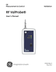
Portable License
Portable License uses USB device - dongle - to store license
information. NL5 operates as full-function version on any PC with the
dongle connected to the USB port. Due to “driverless” dongle
technology no problems using USB ports on different PC models are
expected.
Please note: Portable License does not work on Windows 8.
Network License
Network License is installed on the “License Server” – a computer running a Windows operating
system. The license consists of the NL5LicenseServer.exe Windows application, and network license
file nl5.nll. NL5 can work on any computer that has access to the server computer through the
network. When NL5 starts, it obtains license information from the server. The number of simultaneously
running NL5 applications (number of “seats”) is unlimited.
Personal License
Personal License allows unlimited non-expirable use of NL5 on any PC. The license is issued to a
person, and can be installed only on computers where the license owner is using NL5 on regular basis.
22
User’s Manual
NL5 circuit simulator
II. User Interface
23
User’s Manual
NL5 circuit simulator
NL5 Graphical User Interface (GUI) is based on a standard Microsoft Windows Multi-Document
Interface (MDI) architecture. It consists of different interface components, such as windows, dialogs,
menus, toolbars, etc. NL5 supports many commands and shortcuts that are commonly used in Windows
applications, for instance: Edit | Copy (Ctrl-C), Edit | Paste (Ctrl-V), Window | Tile, using of Ctrl
key along with mouse for select/copy operation, using window scrollbars, etc. Other commands are very
intuitive, so that it would not take long to start working with schematic.
Preferences are used to customize application “look and feel” and default parameters.
Printing allows convenient layout and formatting of windows to be printed.
Data format used in NL5 mostly complies with common engineering and scientific practice. It makes it
easy to learn and use by any person, familiar with other popular tools.
24
User’s Manual
NL5 circuit simulator
Graphical User Interface
Main Window
NL5 Main Window and its components are shown below:
Main Menu
Main Toolbar
Selection Bar
Navigation Bar
Document Windows:
Schematic
Transient
Transient Tools
AC
AC Tools
Other Windows
Components
Variables
Transient/AC Data
Tools
Status Bar
Document Toolbar
Schematic
Transient
AC
25
User’s Manual
NL5 circuit simulator
Main Menu
Main menu contains standard Windows menus (such as File, Edit, Window, Help), and NL5 specific
(Schematic, Transient, AC, Tools).
File:
New (Ctrl-N). Create a new document (schematic).
Open (Ctrl-O). Select a file and open NL5 document.
Save (Ctrl-S). Save active document into its current file (schematic only).
Save As… Select file name and save active document (schematic only).
Save As encrypted… Select file name and save active document with password (schematic
only). To open encrypted document, the same password should be entered.
Save all. Save all currently opened documents.
Close. Close active document.
Properties… Open Schematic Properties dialog box.
Print Setup… Open Print Setup dialog box.
Preview and print…(Ctrl-P) Preview and print schematic and graphs.
Most Recently Used files. Shows up to 10 most recently used files. Click to open the file.
Exit. Close all documents and exit NL5.
Edit:
Cut (Ctrl-X). Cut selection (copy to clipboard and delete).
Copy (Ctrl-C). Schematic: copy selection to clipboard. Transient and AC: copy all traces to
clipboard.
Paste (Ctrl-P). Schematic: paste from clipboard. Transient and AC: paste traces from clipboard
Delete (Del). Delete selection.
Undo (Ctrl-Z). Undo schematic and component parameters change.
Redo (Ctrl-Y). Reverse undo.
Select All (Ctrl-A). Select all schematic elements.
Select Net. Select schematic element and all wires connected to the element either directly, or
through labels (including other sheets).
Format… Format selected elements.
Preferences… Open Preferences dialog box.
26
User’s Manual
NL5 circuit simulator
Schematic:
Components (F3). Show/hide Components window.
Variables (F4). Show/hide Variables window.
Check. Check schematic, show warnings and errors.
Tools… Open Schematic Tools dialog box.
Sheets… Open Sheets dialog box.
Groups… Open Groups dialog box.
Parts list… Open Schematic Properties dialog box, Parts list tab.
Attributes
o Name. Show component name on the schematic.
o Value. Show component main value on the schematic.
Image
o Copy to clipboard. Copy schematic image to the clipboard.
o Save as BMP… Save schematic image in a file in BMP format.
o Save as JPG… Save schematic image in a file in JPG format.
Transient:
Settings… Open Transient Settings dialog box.
Data… Show Transient Data window.
Start (F6). Start transient.
Pause (Space). Pause transient.
Continue (F7, Space). Continue transient.
Stop. Stop transient
Log… Show transient log.
Sweep. Run series of transients transient while changing component parameter or variable.
Save IC. Save current states of all components into their initial conditions (IC).
Tools
o
o
o
o
o
o
o
o
o
DC sweep.
XY diagram.
Amplitude histogram.
Histogram.
FFT.
Eye diagram.
Markers.
Power.
Line snapshot.
27
User’s Manual
NL5 circuit simulator
AC:
Settings… Open AC Settings dialog box.
Data… Show AC Data window.
Start (F9). Start AC analysis
Log… Show AC log.
Sweep. Run series of AC analysis while changing component parameter or variable.
Tools.
o
o
o
o
o
Histogram.
Smith chart.
Nyquist plot.
Nichols plot.
Markers.
Tools:
Script. Open, save, edit, and run script.
Console. Execute commands in the command line.
Sweep. Perform transient and/or AC sweep.
Optimization. Perform transient and/or AC optimization manually iterating schematic
parameters.
HTTP link. Configure and start NL5 HTTP server to provide link with external applications.
Window:
Tile Horizontally. Tile all currently opened windows horizontally.
Tile Vertically. Tile all currently opened windows vertically.
Cascade. Cascade all currently opened windows vertically.
Schematic (F2). Show schematic window.
Transient (F5). Open/Show transient window.
AC (F8). Open/Show AC window.
Navigation Bar. Show/hide Navigation Bar.
Selection Bar. Show/hide Selection Bar.
Status Bar. Show/hide Status Bar.
List of opened windows. Shows all currently opened windows.
28
User’s Manual
NL5 circuit simulator
Help:
Help (F1). Open context Help (nl5.chm).
About… Show information about NL5 version and license.
Support… Show information required for NL5 support, license request, and Network license
configuration.
Check for updates… Obtain information about latest updates (Internet connection required).
Main Toolbar
Main Toolbar provides fast access to often used commands and contains 5 groups of buttons:
File/Edit
Schematic
Transient
Move mouse pointer over the button to see a hint with button description.
Status Bar
Status Bar shows some application-related messages, such as:
Opening documents.
Saving documents.
Checking for updates.
Select Window | Status Bar menu command to show/hide Status Bar.
29
AC
Tools
User’s Manual
NL5 circuit simulator
Selection Bar
Selection Bar consists of tabs, one per letter (only if components are available for this letter). Each tab
contains symbols of components of the “letter” type, and 3 common schematic elements: ground, label,
and connection point. The tab “All” contains symbols of all components.
Right-click
If some components are not visible, click on left/right arrow images to scroll.
Move mouse pointer over component symbol to see a hint with short description of a component.
Click on the symbol to place component on the schematic.
Right-click on the bar to see context menu with relevant commands.
Select Window | Selection Bar menu command to show/hide Selection Bar.
Navigation Bar
Navigation Bar displays all opened documents and windows, and indicates active document and active
window with highlighted icon.
Active document
Active window
Close icon
Right-click
Right-click
30
User’s Manual
NL5 circuit simulator
If some tabs are not visible, click on left/right arrow images to scroll.
Move mouse pointer over icons to see a hint.
Click on the tab to activate the document.
Click on the window icon to activate the window.
Click on the Close icon to close the document.
Right-click on the document tab or empty space of the Navigation Bar to see context menu with
relevant commands.
Select Window | Navigation Bar menu command to show/hide Navigation Bar.
31
User’s Manual
NL5 circuit simulator
Document Windows
NL5 document may have several windows opened at the same time:
Schematic
Transient
Transient Tools
AC
AC Tools
Schematic, Transient, and AC Windows are part of standard Multi-Document Interface, and basically
behave similar to other Windows applications. Document Windows:
Can be minimized and maximized.
Can be arranged within Main Window (Window | Tile, Window | Cascade).
Are listed under Window menu.
Have a related Document Toolbar displayed at the right side of the Main Window.
Closing Schematic window will automatically close the entire document.
Use Navigation Bar or Window menu to navigate between these windows
and arrange them on the screen.
Transient Tools and AC Tools Windows are not part of the Multi-Document
Interface and behave different. Tools Windows:
Are always “on top” of other windows.
Are listed under Transient | Tools and AC | Tools menus.
.
Document Toolbars provides fast access to commands related to active Document
window. There are 3 types of Document toolbar:
Schematic toolbar
Transient toolbar
AC toolbar
Only one toolbar corresponding to active Document Window is visible at a time.
32
User’s Manual
NL5 circuit simulator
Other Windows
Other Windows are not part of the Multi-Document Interface, however they remain open all the time
and do not need to be closed to switch to another window. These windows always show information
related to current active document. Switching between documents automatically updates information in
these windows. Those windows include:
Components Window (Schematic | Components, or F3)
Variables Window (Schematic | Variables, or F4)
Transient and AC Data (Transient/Data, AC/Data)
Tools (Tools | Script, Tools | Sweep, etc.)
Dialog boxes
Unlike Windows, Dialog boxes must be closed to return to the Main Window. Typically, Dialog boxes
have OK and Cancel buttons, and some have Close button. Examples of the Dialog box are:
Preferences (Edit | Preferences).
Schematic Tools (Schematic | Tools).
Transient Settings (Transient | Settings).
…and more.
Help
NL5 help file nl5.chm should be located in the same directory as nl5.exe. The file contains quick
reference information, such as description of operators, functions, commands, components, and models.
For detailed information refer to this Manual. To open Help select Help | Help Main menu command.
For context Help, click F1 hot key anywhere in the program, or Help button
, which is available in
some windows and dialog boxes.
If you cannot see content of Help file, most likely the file is blocked. To unblock:
Locate nl5.chm file in the NL5 directory
Right-click the file, and then click Properties
Click Unblock
33
User’s Manual
NL5 circuit simulator
Hot keys
F1 - Help
F2 - Show schematic window
F3 - Show/hide components window
F4 - Show/hide variables window
F5 - Show transient window
F6 - Start transient
F7 - Continue transient
F8 - Show AC window
F9 - Start AC
34
User’s Manual
NL5 circuit simulator
Preferences
NL5 preferences are used to customize different features of the application, such as “look and feel”
(fonts, colors, formats), default parameters, memory management, etc. Preferences apply to the whole
application, not to the particular document (schematic). Changing preferences does not affect simulation
results.
Preferences are stored in the same directory as nl5.exe, in the file called nl5.nlp. Preferences are
saved into the file every time Apply or OK button in the Preferences dialog box is clicked, and on
exiting NL5. At start-up, NL5 loads last saved preferences from the file.
Preferences can also be saved in the custom preferences file (extension “nlp”), and then opened back
from the file. This feature allows having different profiles for different tasks and switch between them
easily.
Open Preferences dialog box by Main menu command Edit | Preferences. Many context menus do have
Preferences command as well, usually the bottom one in the list:
Selecting this command opens Preferences dialog box directly at context-related page. Preferences
button
is also available in some dialog boxes and windows.
The Preferences dialog box consists of several of pages. Select the page by clicking on the page name in
the tree-view selection window. When any of parameters changed, Apply button is enabled. Then click:
OK – accept changes and close the dialog box.
Cancel – cancel changes and close the dialog box.
Apply – accept changes without closing the dialog box.
35
User’s Manual
NL5 circuit simulator
Preferences
Save/open preferences to/from a file and select color scheme.
Preferences
Save preferences. Save preferences to a file.
Open preferences. Open preferences from a file.
Reset preferences to default.
Color scheme. Color scheme is applied to all Document windows (Schematic, Transient, Transient
Tools, AC, AC Tools). Changing color scheme also changes colors of transient and AC traces.
Color with black background.
Color with white background.
Black and white. This scheme can be temporary used to save black and white schematic or
graph image in the file, or copy to clipboard.
36
User’s Manual
NL5 circuit simulator
Application
Set application options.
Automatically check for updates. Can be set in the range “Never”…”Every 90 days”. NL5 can
automatically check for updates on the NL5 website. NL5 does not download and install updates:
it only notifies if a new update is available. If your PC has anti-virus or/and firewall service
active, you may be asked for granting permission to access NL5 website. If NL5 version,
revision and build are current, a message will be displayed in the Status bar. If new update is
detected, the dialog box with information about update and release notes will be displayed.
Most Recently Used files. Can be set in the range 0…10. This is a maximum number of most
recently used files displayed under File menu.
Subcircuit Library path. A path to “Subcircuit Library” directory. If subcircuit (SubCir model)
is located in the “Subcircuit Library” directory, a short name (without path) can be used as
subcircuit file name.
Beep on errors and messages. Produce sound signal when error or message window is
displayed. This option does not affect sounds generated by system messages (such as “file not
found”, “file already exists”, etc.).
37
User’s Manual
NL5 circuit simulator
Document
Set default properties of a new schematic, and autosave/backup options.
Properties. This is default information to be set in the properties of a new schematic. To view and
edit schematic properties select File | Properties command.
Author.
Organization.
Autosave and backup
Create backup when saving first time. If schematic was loaded from the file, edited, and then
is being saved first time, the file it was loaded from will be converted into backup file with
extension “nl5~”. This prevents from schematic loss by mistakenly overwriting the file.
Save automatically when analysis starts. If selected, NL5 will save schematic automatically
every time transient or AC analysis starts.
Show a reminder when NNN changes are made. If selected, NL5 will show a reminder after
specified number of schematic changes are made:
38
User’s Manual
NL5 circuit simulator
Undo
Max number of Undo steps. Although Undo/Redo buffer can be unlimited, its maximum size
may be specified as well. When new Undo information is being added and buffer size exceeds
specified size, the earliest data will be removed from the buffer.
Clear Undo buffer on schematic save. If selected, Undo buffer will be cleared when schematic
is saved into file. Otherwise, all operations since opening or creating the schematic can be
reversed.
Schematic
Set properties of schematic. New properties will be applied to all new and existing schematic elements,
except elements with customized (formatted) properties.
39
User’s Manual
NL5 circuit simulator
Font size. Set font size of component name and value.
Font. Select font of component name and value.
Line width. Set width of a line (wires and components).
Cursor width. Set width of a line of cursor image.
Attributes grid. Select grid size for component attributes location (relative to schematic grid
size).
Show grid points. If selected, show schematic grid points.
Show node numbers. If selected, show schematic node numbers.
Show hints. If selected, show component name, model, and parameters in the hint box, when
mouse pointer is moved over component.
Colors. Double-click on the item in the list to change the color:
Background
Wire
Ground
Component
Text
Cursor
Grid
Selected
Disabled
40
User’s Manual
NL5 circuit simulator
Drawings
Set default properties of a new drawing. Default properties will be applied only to new drawings.
Existing drawings are not affected by default properties.
Font size. Set font size of a text.
Font. Select font of a text.
Line width. Set width of a line, rectangle, and oval.
Drawings grid. Select grid size for drawings (relative to schematic grid size).
Colors. Double-click on the item in the list to change the color:
Line
Text
41
User’s Manual
NL5 circuit simulator
Mouse (Schematic)
Set mouse wheel action and properties.
Mouse wheel action. Select action to be performed on mouse wheel rotation, along with Ctrl
and/or Shift key state.
no key held – just mouse wheel rotation, no key held.
Ctrl – mouse wheel rotation, and Ctrl key held.
Shift – mouse wheel rotation, and Shift key held.
Ctrl+Shift – mouse wheel rotation, and Ctrl and Shift keys held.
Select action from:
o None
o Zoom
o Hor scroll
o Vert scroll
Invert Zoom – invert Zoom In/Out operation.
42
User’s Manual
NL5 circuit simulator
Components
Set properties of components and variables window and default parameters of a new component.
Components and variables window.
Font size. Set font size of components and variables window.
Font. Select font of components and variables window.
Show units with […] color. Select color to display units of the parameter in the components
window:
o None – do not show units
o Grey – show with grey color
o Black – show with black color
New component. Set default value of a new component:
R, Ohm – resistor
C, F – capacitor
L, H – inductor
Vd (Diode), V – diode forward voltage
43
User’s Manual
NL5 circuit simulator
Symbols
Select symbols of some component types.
Voltage source. Symbol of voltage source, voltage controlled and current controlled voltage
sources.
Current source. Symbol of current source, voltage controlled and current controlled current
sources.
Controlled source. Symbol of controlled voltage and current source.
Resistor. Symbol of resistor, potentiometer, voltage and current controlled resistors.
44
User’s Manual
NL5 circuit simulator
Warnings
Select warnings to be detected and shown during schematic check.
Warnings. Unselect to disable all warnings.
Floating pins. Check for any floating pin of a component.
Non-connected components. Check for components with all pins disconnected.
Overlapping components and wires. Check for overlapping component with another
component and component with wire.
Possibly floating schematic. Check if schematic has at least one ground or label with voltage
source model.
45
User’s Manual
NL5 circuit simulator
Graphs
Set properties of Transient, Transient Tools, AC, and AC Tools windows.
Font size. Set font size of axes numbers.
Font. Select font of axes numbers.
Default trace width. Set width of a new trace.
Default phase width. Set width of a new phase trace.
Markers width. Set markers width.
Gridlines interval (pixels)
Vertical gridlines. Set approximate interval between gridlines in pixels.
Horizontal gridlines. Set approximate interval between gridlines in pixels.
Numbers alignment. Select position of vertical scale numbers.
46
User’s Manual
NL5 circuit simulator
Colors. Double-click on the item in the list to change the color:
Background
Grid
Text
Cursor
Selection
Dimmed storage traces
Table
Set properties of the transient and AC data table.
Text. Set properties of the text in the table, other than phase in AC data table.
Font size. Set font size of the text.
Font. Select font of the text.
47
User’s Manual
NL5 circuit simulator
Phase. Set properties of the phase text in AC data table.
Font size. Set font size of the text.
Font. Select font of text.
Alignment. Select alignment of the text.
Significant digits. Set number of significant digits for data table and Markers Tool.
Time/Frequency.
Data.
Colors. Double-click on the item in the list to change the color:
Text
Phase text
Phase background
48
User’s Manual
NL5 circuit simulator
Legend
Set properties of the Legend window.
Legend font size. Set font size of a legend window.
Max width. If unselected, the width of the Legend window will be automatically adjusted to fit
names of the traces. If selected, the width of the legend window will be automatically adjusted,
but only up to specified width (NNN * height of legend window font).
49
User’s Manual
NL5 circuit simulator
Annotation
Set properties of annotations in Transient and AC windows.
Font size. Set font size of annotation text.
Font. Select font of annotation text.
Line width. Set width of a line for an arrow pointer and a rectangle.
Arrow. If selected, draw arrow pointer.
Draw line with trace color. If selected, use trace color for an arrow pointer and rectangle.
Draw text with trace color. If selected, use trace color for annotation text.
Significant digits. Set number of significant digits for time/frequency and data display.
Time/Frequency.
Data.
Colors. Double-click on the item in the list to change the color:
Line
Text
Background
50
User’s Manual
NL5 circuit simulator
Text
Set properties of a text in Transient and AC windows.
Font size. Set font size of a text.
Font. Select font of a text.
Line width. Set width of a line for an arrow pointer and a rectangle.
Colors. Double-click on the item in the list to change the color:
Line
Text
Background
51
User’s Manual
NL5 circuit simulator
Mouse (Graphs)
Set mouse wheel action and properties. These settings apply to Transient window, AC window, and
most of Transient and AC tools.
Mouse wheel action. Select action to be performed on mouse wheel rotation, along with Ctrl
and/or Shift key state.
no key held – just mouse wheel rotation, no key held.
Ctrl – mouse wheel rotation, and Ctrl key held.
Shift – mouse wheel rotation, and Shift key held.
Ctrl+Shift – mouse wheel rotation, and Ctrl and Shift keys held.
Select action from:
o None
o Zoom (both horizontal and vertical)
o Hor zoom
o Vert zoom
o Hor scroll
o Vert scroll
Invert Zoom – invert Zoom In/Out operation.
52
User’s Manual
NL5 circuit simulator
Transient
Set transient simulation and memory options.
Suppress flickering if graph updates in less than […] ms. If this option is selected, the graph
is not being erased when transient reaches the end of the screen. Transient calculation continues
in the background, and graph is being updated when a new data for the whole screen is available.
As a result, there is no “flickering” of the graph, and simulation is performed faster.
Status update interval, ms. Update transient status with specified interval.
Show notification if cannot pause in […] seconds. If transient pause is requested, and transient
cannot be paused at that moment, a notification window will be displayed. The window can be
closed manually (by stopping the transient, or waiting for pause), or it will be closed
automatically when transient is finally paused.
Memory.
Max memory per trace, MB. Set maximum amount of memory allowed per one trace. If trace
memory exceeds this limit, the beginning portion of the trace will be deleted, and warning
message “One or more traces have been truncated” will show up in the transient status bar.
Max memory per delay and transmission line components, MB (warning). Set maximum
amount of memory allowed for delay and transmission line components. If estimated required
memory exceeds specified limit, a warning message will show up, with the option to continue or
stop simulation.
53
User’s Manual
NL5 circuit simulator
Export traces.
Approximate number of points. When opening Transient Export/View dialog box, time step
value is automatically selected, so that number of points in the table is close to specified number.
Max number of points. Export/View time step cannot be too small, so that number of points in
the table to exceed specified number. Time step be automatically adjusted. This number also
applies to the script command tracename.
HTTP Link
Set HTTP Link options.
Show log. If checked, show HTTP log.
Max number of log lines. Enter maximum number of log lines, or select from drop-down list.
When number of lines exceeds specified maximum, the very first lines will be removed.
54
User’s Manual
NL5 circuit simulator
Printing
Click Preview and print Toolbar button
or select File | Preview and print command to open
Print dialog box. Typical view of the dialog box and its main components are shown below:
Printer selection
and setup
Window
selection list
Preview area
Formatting area
Select printer from drop-down Printer selection list. Click Setup button for printer setup.
Select windows to be printed in the Window selection list. The list contains Title, Comments,
and windows of active document available for printing (opened):
o
o
o
o
o
Schematic.
Transient.
Transient Tools.
AC.
AC tools.
Select checkboxes of windows to be printed.
Please note: if Schematic, Transient, or AC window is maximized, then only that window is
available for printing. In this situation warning message will be displayed below selection list.
Select window name in the list and format window in the Formatting area.
Edit windows layout in the Preview area. Click on the window image to select window. Click
on the window image and drag to move window on the sheet.
Press Print button to print, or Cancel button to close dialog box.
55
User’s Manual
NL5 circuit simulator
Format and layout
In the typical print layout, Title is displayed on the top of the sheet, and
Comments on the bottom. However, they can be moved anywhere on
the sheet. One or more Windows can be displayed anywhere on the
sheet, window size is adjustable in the Window format section. Each
window may have individual Header and Footer. Header is one line
text, and it is formatted in the Header section. Footer may have many
lines, and it is formatted in the Footer section.
The following format buttons are available:
Window
Maximize.
Larger.
Smaller.
Black and white. Select to preview and print color window in black and white format.
Title, Comments, Header and Footer
Larger font.
Smaller font.
Select font.
Select color.
Align left.
Center.
Align right.
56
User’s Manual
NL5 circuit simulator
Data format
Data format used in NL5 mostly complies with common engineering and scientific practice. It makes it
easy to learn and use by any person, familiar with other popular tools.
Case-insensitivity
All the text data in the NL5, such as component names, variables, functions, commands, etc., are caseinsensitive, unless otherwise stated. Lower case and upper case letters are considered the same. For
example:
Rin = RIN = rin
sin(45) = SIN(45)
Numbers
Number format in NL5 is very flexible and complies with many commonly used styles and standards.
Boolean (bool) number can be entered as false or true (case-insensitive):
bool i = true;
bool retvalue = FALSE;
When converted to other types, true is considered as 1, false as 0. When other types are converted to
bool, non-zero value is considered as true, zero value as false.
Integer (int, int64) number can be entered in decimal, binary, octal, and hexadecimal formats.
For binary format, use „0b‟ or „0B‟ prefix, then use numbers 0 and 1:
0b111111111, 0B10101010, 0b10
For octal format, start number with prefix 0 (zero), then use numbers 0…7:
0377, 0123456
For hexadecimal format, use „0x‟ or „0X‟ prefix. Then use numbers 0…9, and capital or low-case letters
A, B, C, D, E, F:
0xFF, 0X10aa, 0x10000
If a value of a number exceeds 32-bit range, it will be automatically converted to int64 type. Use „i64‟
suffix to explicitly define 64-bit integer:
0i64, 0xffffffffi64
57
User’s Manual
NL5 circuit simulator
Floating point (float, double) number can use exponential multipliers E or e, and casesensitive letter multipliers:
Letter
Multiplier
12
T
10
109
106
103
10-3
10-6
10-9
10-12
G
M, mg
k, K
m
u, mk
n
p
For example:
1.3e+3
47E-9
100k
0.33u
0.33mk
2.2M
Letter multiplier can be followed by any text, which is considered as units and will be ignored:
1.3kOhm
47nF
0.1mkH
333ps
Any text that does not begin with letter multiplier is considered as units and will be ignored:
1.3Ohm
0.001F
0.1H
333apples
Letter multiplier and units (with or without letter multiplier) can be used instead of a decimal point:
1k3
5n6
3nF3
47F0
2s2
Zero before decimal point or letter multiplier can be omitted. For example:
.47
n47
uF5
A number can be entered in decibels, using suffix db (case-insensitive). It will be automatically
converted to a standard number (allowed for positive numbers only):
20db = 100
3.01dB = 1.41416472507
6DB02 = 1.99986186963
Infinite value is denoted by:
inf
Complex (complex) number consists of real and imaginary parts of floating point type. Imaginary part
of a complex number has lower case letter „j‟ at the end of a number. Letter „j‟ cannot be used alone,
only as a suffix:
50+45j
1+1e-3j = 1+.001j
30j
1+j : wrong! Correct format: 1+1j
58
User’s Manual
NL5 circuit simulator
The following predefined constants (case-insensitive) can be used:
PI = Pi = pi = 3.14159265359
RAD = Rad = rad = 180/pi = 57.2957795131
LOW = Low = low : low logical level, V
HIGH = High = high : high logical level, V
Constant RAD can be used to convert degrees to radians and radians to degrees:
degrees = radians * RAD
radians = degrees / RAD
where degrees is value in degrees, and radians is value in radians.
All numerical component parameters, and most of other parameters in NL5 are floating point (double).
Those parameters can be entered in any format, however after that they are automatically converted and
stored in the floating point format.
When floating point number is displayed, an engineering notation, with exponential multiplier and
power of ten to be multiple of three, is used:
Entered
1k3
47e-8
5600000
Displayed
1.3e+3
470e-9
5.6e+6
Names
Component. When a new component is created, it is assigned a default name: „letter‟ plus number:
R1, V2, C123
Then the component can be renamed. The name is case-insensitive and may contain any (almost)
characters and symbols. When used in formula or function, the name is enclosed in quotes:
“R out”, “V pulse”, “+12V”
However, if the name starts with letter and contains letters and numbers only, it can be used without
quotes:
Rout, V123, Plus12V
If the component has been renamed, its name will be automatically modified in all appearances of the
component name in trace names, formulas and functions.
To access component‟s parameter in the formula, function, or script expression, use component name
followed by dot „.‟ and parameter name:
R1.R, V2.slope, C123.IC, “R out”.R
59
User’s Manual
NL5 circuit simulator
If parameter name is not specified, a first parameter of the component will be used:
R1 = R1.R
C2 = C2.C
(Exception: when parameter is used in Function model, it should be explicitly defined). To access
component which is part of the subcircuit use subcircuit component‟s name followed by dot „.‟ and
component‟s name in the subcircuit. A nesting level is unlimited: components inside subcircuit, which in
turn is part of subcircuit, can be accesses by similar notation:
X1.R2
X1.F1.V3.period
where X1 and F1 are subcircuits.
To access global variable name of the C model of Code component X1 (in a script or command-line) use
the following notation:
X1.name
To access component‟s model name (in a script or command-line) use component name followed by dot
„.‟ and “model”:
V1.model = pulse
Schematic variable. Schematic variable name has the same format as a component, except it does not
have parameters. For example:
Freq, “max limit”, X1.var
Please note that this applies only to a schematic variable: a variable defined in the Variables window.
Variables used in C code (script, Code component) comply with C language standard.
Trace. The basic name of transient or AC trace that holds current simulation data consists of the letter
specifying type of the trace (V,I,P), followed by component‟s name in parentheses:
V(R1), I(C2), P(L3)
The trace with basic name can‟t be renamed. When trace is duplicated, loaded from file, or pasted, it can
be renamed to an arbitrary text:
“Copy of V(R1)”
“Old trace of R1”
“V pulse”
The name of the trace of Function type is the function itself. Renaming the trace will change the
function:
“V(r1)*V(r1)/r1”
60
User’s Manual
NL5 circuit simulator
Trace and cursors data. Trace and cursors data shown in the transient or AC table (value at cursor,
min, max, mean, etc.) and trace value at specified time can be used in the script expressions. The trace
should be added to the Transient or AC Data, but does not need to be displayed on the graph or in the
table. To access trace data use the following notation:
Cursors (screen)
left
right
delta
Transient amplitude
V(R1).(1.2)
V(R1).left
V(R1).right
V(R1).delta
V(R1).min
V(R1).max
V(R1).pp
V(R1).mean
V(R1).rms
V(R1).acrms
– value at t=1.2
– value at the left edge of the screen or left cursor
– value at the right edge of the screen or right cursor
= V(R1).right–V(R1).left
– minimum
– maximum
– peak-to-peak (max–min)
– mean
– RMS
– RMS of the signal with subtracted mean value
AC magnitude
V(R1).(1.2)
V(R1).left
V(R1).right
V(R1).delta
V(R1).min
V(R1).max
V(R1).pp
V(R1).slope
– position of the cursor, or left edge of the screen
– position of right cursor, or right edge of the screen
= right-left
– value at f=1.2
– value at the left edge of the screen or left cursor
– value at the right edge of the screen or right cursor
= V(R1).right–V(R1).left
– minimum
– maximum
– peak-to-peak (max–min)
– slope of the gain, dB/dec
AC phase
V(R1).phase.(1.2)
V(R1).phase.left
V(R1).phase.right
V(R1).phase.delta
V(R1).phase.min
V(R1).phase.max
V(R1).phase.pp
– value at f=1.2
– value at the left edge of the screen or left cursor
– value at the right edge of the screen or right cursor
= V(R1).right–V(R1).left
– minimum
– maximum
– peak-to-peak (max–min)
61
User’s Manual
NL5 circuit simulator
Operators
NL5 supports the following arithmetic and logical operators:
++
!
<
&&
+=
&=
-~
<=
||
-=
^=
+
<<
>
?:
*=
|=
>>
>=
*
&
==
/
^
!=
/=
<<=
%=
>>=
(int64)
(float)
(double)
%
|
and type-casting operators:
(bool)
(int)
(complex)
See full operators list with description in the Attachment 2.
Functions
NL5 offers many standard and NL5-specific functions. The functions can be used in the C code (script,
Code component), traces of Function type, and in Function model of some components.
For the convenience of users, there may be several names used for the same function (for example
log10 and lg), so that the user can use the name he/she is more comfortable with. The following
functions are available:
sin
cos
tan, tg
asin
acos
atan
atan2
sqrt
sqr
sq
pow
pwr
exp
ln, log
lg, log10
lb, log2
mag, abs
phase
re
im
sign
round
floor
ceil
par
random, rand
gauss
limit, lim
islow
ishigh
db
See full functions list, description, and examples in the Attachment 3.
62
sum
mean
max
min
bool
int
int64
float
double
complex
User’s Manual
NL5 circuit simulator
Expressions
Expression may consist of:
Numbers.
Predefined constants.
Names of components, parameters and variables.
Local script or C-code variables.
Operators.
Functions.
Parentheses with unlimited nesting level.
For example:
2*2
2<<3
sin(2*PI*f)
max(R1,R2,R3)
1/((R1+R2)*C1)
// “f” is a schematic variable
Expression can be used instead of number in most entry fields in the dialog boxes, and for some
component parameters. When Enter key is pressed, or OK or Apply button (if exists) is clicked, the
expression is immediately evaluated and replaced with the numerical value.
63
User’s Manual
NL5 circuit simulator
C language
Simplified C language interpreter is implemented in the NL5. It is used in the script and in the C model
of Code component. Although not all standard C features are supported, it is quite sufficient for many
tasks.
The following C keywords, statements, and operators are available:
bool
int
int64
float
double
complex
if…else
for
while
do…while
switch
case
default
continue
break
return
The following C language features are currently not implemented in NL5:
Structures and unions.
Pointers and references.
goto statement.
Multi-dimensional arrays.
Comments
Use // to comment text until the end of the line, or delimiters /* and */ to comment block of the text.
Delimiters /* and */ can be nested.
for( i=0; i<10; ++i ) { // this is a comment
/* This block is commented out
x=i*2;
y=i/10;
*/
x=i;
}
Data types
The following data types are supported:
bool – boolean (true/false).
int – 32-bit signed integer.
int64 – 64-bit signed integer.
float – same as double.
double – 8-byte floating point.
complex – consists of double real and imaginary parts.
64
User’s Manual
NL5 circuit simulator
Variables
All variables must be declared before use. To declare a new variable, use keyword bool, int, float,
double, or complex with the variable name. A variable can be initialized in the declaration:
double x;
double x, y, z;
double x=1.0;
int i=2, j=5;
bool flag;
complex c = 0.5+0.5j;
Arrays
Only one-dimensional arrays are supported. Index is zero-based. An array can be initialized in the
declaration:
double x[100];
int array[] = { 1, 2, 3, 4, 5 };
Statements and operators
if…else. Conditional statement.
if(i<=0) R1=1.0k;
else if(i==1) R1=2.0k;
else {
R1=3.0k;
C1=1n;
}
for. Loop operator.
for( i=0; i<10; ++i ) {
x[i]=1<<i;
y+=x[i];
}
“Foreach” loop operator. The code is executed for all values from the comma-separated list.
for( i=1,5,10,50,100 ) {
y*=i;
}
while. Loop operator.
i=0;
while( i<10 ) {
x[i]=1<<i;
++i;
}
65
User’s Manual
NL5 circuit simulator
do…while. Loop operator.
i=0;
do {
x[i]=1<<i;
++i;
}
while( i<10 );
switch. Selective structure.
switch(i) {
case 1: x=1; break;
case 2: x=2; break;
default: x=3; break;
}
continue. Skip the rest of the code in the current loop.
for( i=0; i<10; ++i ) {
x[i]=1<<i;
if(i==5) continue;
y+=x[i];
}
break. Leave current loop or switch statement.
for( i=0; i<10; ++i ) {
x[i]=1<<i;
if(i==5) break;
y+=x[i];
}
return. Stop execution of the code immediately and exit.
for( i=0; i<10; ++i ) {
x[i]=1<<i;
if(x[i]==0) return;
y/=x[i];
}
Please refer to publicly available resources for general C language syntax description and reference.
66
User’s Manual
NL5 circuit simulator
Script
Script is a program which allows automating simulation process. Using script you can open/close
schematic files, modify component parameters, run simulation, analyze the data, save/export simulation
results etc.
Script can be executed from NL5 command line, or at Script page of Tools window. Script commands
can also be executed from command line in the Console page of Tools window, and through HTTP link
from external applications. This allows using NL5 as an “add-on” simulation engine with popular
engineering tools such as MATLAB®, Python, and others.
Script syntax
Script is written on C language, and is executed by C language interpreter built in NL5. All C operators
(Attachment 2) and functions (Attachment 3) can be used in the script. In addition, NL5-specific script
commands (Attachment 4) can be used to run simulation, analyze data, and save simulation results.
Component parameters and schematic variables can be used in expressions and can be modified
similar to C variables:
R1 = tau / C1;
freq = 1. / V1.period;
// “freq” is schematic variable
Trace and cursors data can be used in expressions. The data correspond to the values displayed in the
Transient or AC Data table. In order to use trace data, the trace should be added into the Transient or AC
data, but does not need to be displayed on the graph or in the data table. For example:
x = V(out).max – V(out).min;
if( V(C1).(3.45) > threshold ) break;
charge = I(C1).mean * delta;
Script commands
Script commands are used to open schematic, control simulation process (run and continue simulation),
and save simulation data in different formats. The following script commands are available:
ac
clear
close
cont
cursors
display
exit
export
logdata
open
pause
ready
return
rununtil
save
savedata
saveiс
sleep
stop
store
storetext
traces
tracename
tran
See full script commands list, description, and examples in the Attachment 4.
67
User’s Manual
NL5 circuit simulator
Please note that unlike standard C function calls, script commands parameters do not need to be
enclosed into parentheses. However, for consistency of the code, parentheses can be used as well. For
example:
open( rc.nl5 );
open rc.nl5;
tran( 0, 1, 1m );
close();
clear;
Script examples
Set component parameters. Component parameters have been calculated in external application (for
instance, Excel), or entered manually and saved into the text file in the name=value format:
R1 = 5.1;
C1 = 12e-9;
V3.period = 0.01;
Run the script to apply new parameters to components.
Sweep parameter. Component parameter is changing in specified range, transient analysis performed
for each parameter, results placed into storage:
for( R1=1; R1<=10; R1+=1 )
{
tran;
store R1;
}
Sweep parameter from the list. Component parameter is assigned value from the list, AC analysis
performed for each parameter, results placed into storage:
for( V1.period = 1m, 2m, 10m, 50, 100m )
{
ac;
store V1.period;
}
Sweep variable. Local variable is changing in some range, component parameters modified, transient
analysis performed, results placed into storage:
double freq;
for( freq=1; freq<=10; freq*=1.1 )
{
V2.period = 1 / freq;
R2 = 1 / (freq * C5);
tran;
store freq;
}
68
User’s Manual
NL5 circuit simulator
Wait for condition. Transient is running until peak-to-peak value of the trace is less than specified
threshold. When done, Initial Conditions are saved.
double threshold = 1e-6;
tran;
while( v(c1).pp > threshold ) cont;
saveic;
Perform analysis for specified file, save data, exit application. Schematic file is loaded into NL5,
component parameters changed, transient analysis performed, traces exported into “csv” file, NL5
closed. This script can be executed from command line.
open lcr.nl5;
R1=100;
C1=1n5;
tran;
export data.csv;
exit;
Perform analysis for specified file, log data, exit application. Schematic file is loaded into NL5,
component parameter swept, transient analysis performed, traces data logged into text file, NL5 closed.
This script can be executed from command line.
open lcr.nl5;
logdata lcrdata.csv, r1, v(r1).mean, v(r1).rms;
for( R1=100; R1<=1000; R1+=100 )
{
tran;
logdata;
}
exit;
69
User’s Manual
NL5 circuit simulator
III. Schematic
70
User’s Manual
NL5 circuit simulator
The following simplified diagram shows schematic structure and operations:
Schematic is shown and can be edited in the Schematic window. Any document must have Schematic
window: closing Schematic window will automatically close the entire document. Components and
variables are shown and can be edited in the Components Window and Variables Window. Several
Dialog boxes, such as Tools, Sheets, Groups, Format, are used to perform other operations on the
schematic and Schematic Window. Schematic data is used for Transient and AC analysis.
71
User’s Manual
NL5 circuit simulator
Schematic window
Typical view of schematic window and its main components are shown below:
Schematic area
Right-click
Right-click
Sheet selection
Shift/Ctrl
indicators
Status bar
Schematic is shown in the Schematic area.
Sheet selection area contains sheet tabs. Click on the tab to select sheet.
Right-click on the Sheet selection area to see context menu with relevant commands.
Shift/Ctrl indicators are highlighted when Shift and/or Ctrl key are depressed.
Status bar shows hint related to current position of mouse pointer and Shift/Ctrl state.
Move mouse pointer over “splitter” area
Sheet selection area.
Right-click on the schematic to see context menu with relevant commands.
, then press left mouse button and drag to resize
72
User’s Manual
NL5 circuit simulator
Schematic area contains schematic elements, drawings, grid points, and cursor.
Cursor
Schematic grid points
Schematic elements
Drawings
Drawings
Label
Lines
Component
Rectangle
Wire
Connection
Oval
Attributes
Name
Text
Value
Ground
Schematic elements include wire, connection, ground, label, and component. Schematic
elements represent “electrical” part of the schematic used for simulation.
Drawings include line, rectangle, oval, and text. Drawings are used for comments and notes.
Grid points are reference points for cursor and schematic elements.
Cursor is used to place/select schematic elements and can be placed at grid points only.
Most of editing commands apply both to schematic elements and drawings. Unless otherwise stated, the
word “drawings” is omitted in the description of those commands.
All elements are initially placed on the schematic with default properties (color, width, style, font, etc.),
defined on Schematic page of Preferences dialog box. Properties of any element can be customized by
formatting. Changing default properties of schematic elements applies to all existing elements on the
schematic, except elements with custom properties. Changing default properties of drawings does not
affect existing drawings.
73
User’s Manual
NL5 circuit simulator
Editing schematic
Schematic editing and navigation can be performed by commands available in the Main Menu,
schematic context menus, Main Toolbar, Schematic toolbar, shortcuts, keyboard keys, and mouse. NL5
supports many commands and shortcuts that are commonly used in Windows applications (such as Edit
| Copy (Ctrl-C), Edit | Paste (Ctrl-V), and more), using of Ctrl key with mouse for select/copy
operation, using window scrollbars, etc. Other commands are very intuitive, so that it would not take
long to start working with schematic.
Very often, the same operation can be performed by different ways. For instance, selecting and placing
new component on the schematic can be done using keyboard keys only, mouse only, or both. It is
user‟s choice to select the most effective and convenient one. A complete commands list is provided.
There are 6 schematic editing modes:
Selection. Select elements, blocks; place components.
Wire. Draw wire, place components.
Scrolling. Scroll schematic.
Line. Draw line.
Rectangle. Draw rectangle and square.
Oval. Draw oval and circle,
The editing mode can be selected by clicking the button on the schematic toolbar. Also, there are some
quick ways to switch between most often used modes:
Press Space to switch between Selection and Wire modes:
Point mouse pointer to empty space, press and hold Shift,
click and drag mouse to scroll schematic. Release Shift
to return to Selection mode:
Space
Shift down
Shift up
Space, Esc
Press Esc or Space in all modes to switch to Selection mode:
74
…
User’s Manual
NL5 circuit simulator
Cursor
Cursor is used as a marker to place a new schematic element: wire, ground, connection, component, or
label. Cursor is used in two modes: Selection and Wire:
Selection mode
Wire mode
Use Left, Up, Right, Down keys to change cursor direction and move cursor.
To change cursor direction by mouse, click close to the corner pointing to a new direction.
Click on the schematic to move cursor to a new point.
Press Home to center cursor on the screen.
Press Space to switch between Wire and Selection modes.
In Selection mode, move cursor on the element and click to select the element.
In Wire mode, move cursor to draw a new wire.
When cursor reaches the edge of schematic window, the window will scroll automatically.
Wire
The following examples show how to place wire using keyboard and mouse.
Keyboard. Move cursor to the starting point using arrow keys (Left, Up, Right, Down). Press Space to
switch to Wire mode, then move cursor using arrow keys. A new wire appears in selected state. To
complete the wire, press Space to switch back to Selection mode, or change cursor direction and
continue new wire in another direction:
Press Space
Press Right…
Press Up
Press Up…
Press Space
Mouse. Click Wire button
to switch to Wire mode. Click on the wire starting point, hold mouse
button, and drag to the ending point of the wire, then release mouse button. You can do two orthogonal
pieces of wire at once. Click Selection button
to switch back to Selection mode:
Click Wire button
Click and drag right, then up
75
Release left button
Click Selection button
User’s Manual
NL5 circuit simulator
You can use both keyboard and mouse to draw wires. For instance, use Space key to switch between
Selection and Wire modes, and use mouse to draw wires.
To draw diagonal wire hold Ctrl key while dragging and releasing mouse button. Another way to make
diagonal wire is to select existing wire, then click and drag the end of the wire:
Hold Ctrl key, click and drag
Click to select
Click and drag the end
Connection
Three wires coming to one point are always connected. Connection point will be automatically placed
here during schematic check. Two crossing wires are not connected by default. To connect these wires
place connection point: move cursor to the crossing and press „.‟ (dot) key, or move mouse pointer over
crossing and click on Connection image (
) in the Selection Bar.
Automatic
connection
No connection
Press „.‟
Connection
Diagonal wire
not connected!
All the unnecessary connection points will be automatically deleted during schematic check.
Warning: diagonal wire may be not connected to other wires even if connection point is placed at the
crossing. Try to avoid connection of two diagonal wires at one point.
Ground
To place a ground press „G‟ key or click on Ground image (
) in the Selection Bar. The ground is
common for entire document, including all sheets and all subcircuits.
76
User’s Manual
NL5 circuit simulator
Component
Each component type has a designated letter and symbol.
Letter identifies functional group of a component. For instance, all component types with letter „S‟ are
switches. Selection Bar has a tab designated for each letter. When placing component by keyboard, the
letter key is used to select component type. Default name of a component begins with this letter.
Symbol is an image of a component type: how component is displayed on the schematic. Selection Bar
contains symbols of all available component types.
Some component types are “customized”: symbol of those components, as well as number of pins, pins
location and names, can be edited in the Edit Component dialog box. The dialog box shows up
automatically at the moment when component is being placed, and can be opened any time later. See
Editing customized component chapter for details.
The following diagram and example show the process of placing component.
Select letter
Keyboard
Press „V‟, Enter
Selection Bar
OR
Click on symbol
Select model
Schematic Window
Components Window
Double-click
on component
Edit parameters
77
User’s Manual
NL5 circuit simulator
Selection Bar. Select tab with required
component type (V), then click on component
symbol to place component (“Voltage
controlled voltage source”). New component
shows up in “selected” state, so you can
immediately rotate, mirror, flip, or select view
as needed.
Keyboard. Press key with the letter
designated to the component type (V).
If several components types are
available for this letter, press letter key
again until desired type of a component
shows up. Use arrow keys to move a
new component, or click and drag new
component by mouse. To place
component press Enter. To cancel,
press Delete or Esc.
Schematic with a new component, which is not set yet and is shown in cursor‟s color is sometimes
called to be in New component mode.
When component is placed above existing wire, a
piece of the wire underneath the component is
automatically removed, so that no editing of the wire
is required.
A new component has automatically generated name. The name begins with type specific letter,
followed by unique number. Then, the component can be renamed in the Components window.
When component is placed on the schematic, its image can be modified (flipped, mirrored, rotated) to fit
schematic better. In addition, some component types may have several views. Commands that modify
image and change views are also applied to a new component while placing component using keyboard,
before pressing Enter.
Along with schematic, a new component will show up in the Components window. In this window, you
can see all the models available for component type. When model is selected, parameters of the model
are shown and available for editing. See Components Window chapter for details.
To switch to Components Window from schematic, place cursor on the component and press Enter, or
double-click on the component. In this case, if you finish editing parameters by pressing Enter or Esc,
you will switch back to the schematic.
78
User’s Manual
NL5 circuit simulator
Component View
Some component types have several views: almost identical images with slight modification. Different
views may have different pinouts, or indicate some functionality difference. A few examples of different
views:
Polarity of control signal and source:
Logical function of logical components:
Inverted and non-inverted inputs/outputs:
To change the view of the component, use the following buttons and shortcuts:
Next view. Select next view of a component with multiple views.
„+‟, „-‟ keys. Select next/previous image of a component by changing view, mirror and/or flip
component, whichever is applicable.
These commands can also be applied to a new component while placing component using keyboard,
before pressing Enter.
79
User’s Manual
NL5 circuit simulator
Label
Label is similar to component, except that there can be many labels with the same name in the
schematic. All labels with the same name are electrically connected. (Labels in the subcircuit are local to
the subcircuit and are not connected with the main schematic). Labels can be used:
To connect different points of the schematic without wire.
To connect parts of the schematic located on different sheets.
As a simulation “probe” (V trace).
As a voltage source.
The following diagram and example show the process of placing label.
Keyboard
Press Enter
Selection Bar
OR
Click on label
Select model
Components Window
Schematic Window
Double-click
on label
Edit parameters
To place label press Enter on the wire or empty space, or click on Label image (
) in the Selection
Bar. Label dialog box will show up. Enter new label name or select existing label from drop-down list
and click OK. A label will immediately show up on the schematic and in the Components Window. To
set up model and parameters of the label, place cursor on the label and press Enter, or double-click on
the label to switch to Components window.
80
User’s Manual
NL5 circuit simulator
Attributes
Attributes of the component and label include Name and Value. The following attributes display modes
are available:
No attributes
Name only
Value only
Name and Value
Press Tab key to toggle attributes display mode, or select attributes under Schematic | Attributes Main
Menu item.
Attributes can be placed with resolution higher than schematic grid. The “attributes grid” can be set up
in the range “1/1” down to “1/32” of schematic grid. Attributes grid can be changed on Schematic page
of Preferences dialog box.
To move an attribute, select component first, the click on the attribute and drag it:
Click (select)…
Click…
Drag…
Release…
Unselect
To change attributes orientation select component and or click Rotate attributes button
Ctrl-T.
, or press
By default, Value is either first parameter of the component‟s model, or model name. List of parameters
displayed for specific component can be customized in the Format dialog box. Right-click on the
component, select Format command in the context menu, then select Attributes page. For the
component highlighted in the list, select format and values to display.
81
User’s Manual
NL5 circuit simulator
Drawings (line, rectangle, oval)
Drawings (line, rectangle, oval) do not affect functionality of the schematic and are used solely as a
“decoration”. Drawings can be placed with resolution higher than schematic grid. The “drawings grid”
can be set up in the range “1/1” down to “1/32” of schematic grid. Drawings grid can be changed on
Drawings page of Preferences dialog box.
To place line, click Line button
To place rectangle, click Rectangle button
To place oval, click Oval button
to switch to Line mode.
to switch to Rectangle mode. .
to switch to Oval mode.
Click on the starting point, hold mouse button, and drag to ending point of the drawing, then release
mouse button:
Line
Rectangle (square)
Oval (circle)
To draw square or circle, hold Ctrl key while dragging and releasing mouse button.
Click Selection button
to switch back to Selection mode. To change size and/or shape of the
drawing select drawing, then click square marker and drag:
Click to select
Click and drag
When placed, drawings show up in a default format. To change color, line width and type of drawings,
select drawings, then select Edit | Format command from Main menu, or right-click on the drawings
and select Format command from context menu. To format just one drawings element, simply doubleclick on the element.
82
User’s Manual
NL5 circuit simulator
Text and Variables
To enter text click Insert text button
.Text dialog box will show up:
Enter text in the text box. The text will be simultaneously shown on the schematic:
The text can be formatted using toolbar buttons and controls:
Alignment. Set alignment of multi-line text.
Align left.
Center.
Align right.
Orientation. Change orientation of the text.
Rotate left.
Rotate right.
Font. Change size of the font or select specific font type and options.
Larger font.
Smaller font.
Select font.
83
User’s Manual
NL5 circuit simulator
Run script. Run script from the text (the text is considered to be a script, and will be executed).
Outline and pointer options
Outline. Draw outline rectangle.
Pointer. Draw pointer line from the text to specified point.
Arrow. Draw pointer line with arrow.
Lock pointer. Lock the end of the pointer: the end of the pointer
will not move even when text is being moved.
Line width. Specify line width of the outline and pointer.
Color. Double-click on the item in the list to change the color.
Click Close button when done to close dialog box.
To edit the text, double-click on the text, or right-click on the text and select Edit text command from
context menu. The same Text dialog box will show up.
To move the text, click on the text and drag. If pointer is locked,
only text will move. To move the pointer only, click on the text to
select, then click and drag square marker at the end of pointer.
To place list of variables on the schematic click Insert variables
button
. Variables and their values will be shown similar to a
text. The text can be formatted, but cannot be manually edited: it will be automatically updated as
variables or their values change.
84
User’s Manual
NL5 circuit simulator
Scrolling and Zooming
To scroll schematic use any of the following methods:
Move schematic cursor to the edge of schematic window, the window will scroll automatically.
Move mouse pointer to the edge of schematic window. Mouse pointer will take “big arrow”
shape. Click or hold left mouse button to scroll schematic:
In Selection mode
, point mouse pointer to empty space, hold Shift key, then click and drag
schematic. Shift key will temporary to Scrolling mode.
Hold Ctrl key and rotate mouse wheel to scroll horizontally.
Hold Shift key and rotate mouse wheel to scroll vertically.
Use Shift-Up, Shift-Down, Shift-Right, Shift-Left keyboard shortcuts.
In Scrolling mode
Press Home to center cursor on the screen
Point and double-click on the schematic to set cursor and center it on the screen
click and drag schematic, or press Up, Down, Right, Left keys.
To zoom schematic use any of the following methods:
Rotate mouse wheel to zoom-in and zoom-out.
Click schematic toolbar buttons or use keyboard shortcuts:
o PgUp - zoom-in
o PgDn - zoom-out
o Ctrl-Home - fit all schematic to the screen
o Shift-Home - fit selection to the screen
Right-click on schematic window to open context menu, select Zoom item, then select
schematic scale in percent (25%…250%).
85
User’s Manual
NL5 circuit simulator
Select and Unselect
To select one schematic element, point and click on the element.
To select a block, point on the empty space, click and drag selection rectangle. Depending on
state of Ctrl and Shift keys at the moment of releasing mouse button, the following selection can
be done:
o No keys depressed. Only components completely located in the selected area; only part of the
wires located in the selected area. Selection is bounded by a rectangle.
o Ctrl key is depressed. All components and wires with any part in the selected area. Selection
is not bounded by a rectangle.
o Shift key is depressed. Only components and wires completely located in the selected area.
Selection is bounded by a rectangle.
No keys depressed
Ctrl key depressed
Shift key depressed
To add new selection to existing one, press and hold Ctrl key, then select a new element or a
new block.
To select all elements, press Ctrl-A.
Right-click to select element and open context menu.
Select Net command in the context menu selects schematic element with all wires connected to
the element either directly, or through labels (including other sheets).
Moving schematic cursor automatically selects element under the cursor.
To unselect, point and click on empty space, or press Esc.
To unselect a block, point and click on empty space outside the block, or press Esc twice.
Pressing Esc first time removes block rectangle, pressing second time unselects all elements.
Schematic with selection bounded by a rectangle is sometimes called to be in Block selected
mode.
86
User’s Manual
NL5 circuit simulator
Delete
To delete elements, select elements or block, then press Del, or click Delete button
.
To delete entire sheet, right-click on Sheets selection tab, then select Remove sheet command in the
context menu. The sheet will be deleted permanently and can‟t be restored. Schematic should contain at
least one sheet, so the last sheet cannot be deleted.
Move and Copy
To move element: click on the element and drag to a new location:
To move schematic element with rubber bands: hold Shift key, click on the element and drag to
a new location:
To move block: click on selection and drag to a new location.
87
User’s Manual
NL5 circuit simulator
To move block with rubber bands: hold Shift key, click on selection and drag to a new location.
To copy element: hold Ctrl key, click on the element and drag to a new location.
To copy schematic element with rubber bands: hold Ctrl and Shift keys, click on the element
and drag to a new location.
To copy block: hold Ctrl key, click on selection and drag to a new location.
88
User’s Manual
NL5 circuit simulator
To copy block with rubber bands: hold Ctrl and Shift keys, click on the element and drag to a
new location.
Move/copy operations can also be done with standard commands and shortcuts Edit | Copy (Ctrl-C),
Edit | Cut (Ctrl-X), and Edit | Paste (Ctrl-V). Use these commands to move/copy elements to another
sheet, document, or NL5 application as well.
When component is moved/copied above existing
wire, a piece of the wire underneath the component
will be automatically removed, so that no editing of
the wire is required:
Disable and Enable
Schematic elements can be disabled. Disabled elements are shown in “disabled” color and are not used
for simulation. Disabling elements allows temporary exclude elements from simulation without deleting.
To disable, right-click on selection and select Disable command from context menu. To enable, select
Enable command.
89
User’s Manual
NL5 circuit simulator
Mirror, Flip, Rotate
To change orientation of a schematic element, use Rotate, Mirror, and Flip commands:
Rotate right (Ctrl-R). Rotate right (clockwise).
Rotate left (Ctrl-L). Rotate left (counterclockwise).
Mirror (Ctrl-M). Mirror (flip around vertical axis).
Flip (Ctrl-F). Flip (flip around horizontal axis).
Select element
Rotate right
Rotate left
Mirror
Flip
Those commands can be applied to selected block as well:
Select block
Mirror
Flip
90
User’s Manual
NL5 circuit simulator
To rotate block, select the block, then place cursor to the center of rotation inside the block:
Select block
Rotate left
Format
All elements are initially placed on the schematic with default properties (color, width, style, font, etc.).
After that properties of any element can be customized by formatting. To format selected elements,
right-click on the selection and select Format command from context menu, or select Edit | Format
command from Main menu. Format dialog box will show up:
91
User’s Manual
NL5 circuit simulator
Only properties applicable to selected elements will be enabled. For instance, if only wires are selected,
all fields except Schematic Line width and Wire color will be disabled. If selected elements have
different value of the same property, corresponding field will be enabled, but left blank. Leave it blank
to keep individual values unchanged, otherwise they will be set to the same value.
Show selection in normal colors. When Format dialog box opens, all selected elements have
the same, “selected” color. Select this checkbox to see all elements in their normal color.
Schematic.
Line width. Line width of all selected schematic elements: wires, components, labels, and
grounds.
Font size. Font size of component attributes.
Color. Double-click on the item in the list to change the color.
Reset to default. Click the button to reset custom properties back to default.
Drawings.
Line width. Line width of all selected drawings: lines, rectangles, ovals and texts.
Style. Line style for line, rectangle, and oval.
Arrows. Arrows control for lines.
Text alignment. Alignment of multi-line text.
Select font. Select font of the text.
Color. Double-click on the item in the list to change the color.
OK. Accept changes and close the dialog box.
Cancel. Ignore last changes and close the dialog box.
Apply. Accept changes without closing the dialog box.
Undo and Redo
To undo schematic and component parameters changes, click Ctrl-Z, or click Undo button
. To
reverse undo operation, click Ctrl-Y, or click Redo button
. An unlimited number of undo
operations may be reversed with the redo command.
Size of the Undo buffer is unlimited, and by default the buffer keeps all changes since the document is
created or loaded from the file, and buffer is cleared when schematic is saved into the file. However, for
optimal performance the size (number of undo steps) may be specified on the Document page of
Preferences dialog box. Also, unselecting option “Clear Undo buffer on schematic change” allows
keeping all changed done since the file was created or loaded from the file, and never clear the buffer.
Undo operation does not apply to component parameters changed during Sweep, Optimization, Script
execution, or done from Console tool.
92
User’s Manual
NL5 circuit simulator
Schematic editing commands
The following schematic editing commands, buttons, and shortcuts are available in the Main Menu,
Main Toolbar, Schematic Toolbar, and schematic context menu.
Show schematic window (F2).
Schematic Tools.
Check schematic.
Sheets. Open Sheets dialog box.
Groups. Open Groups dialog box.
Parts list. Show parts list in the Properties dialog box.
Attributes ►
o Name. Toggle attribute name display.
o Value. Toggle attribute value display.
Image ►
o Copy to clipboard. Copy image of schematic window to the clipboard.
o Save as BMP. Save image of schematic window to a file in “bmp” format.
o Save as JPG. Save image of schematic window to a file in “jpg” format.
Cut (Ctrl-X). Cut selection (copy to clipboard and delete).
Copy (Ctrl-C). Copy selection to clipboard.
Paste (Ctrl-V). Paste from clipboard.
Delete (Del). Delete selection.
Undo edit (Ctrl-Z). Undo schematic and component parameters change.
Redo edit (Ctrl-Y). Reverse undo.
Select All (Ctrl-A). Select all schematic elements.
Select Net. Select element, and all wires connected to the element either directly, or through
labels (including other sheets).
Format. Format selected elements.
Preferences. Open Preferences dialog box.
Help (F1). Press F1 to get help on schematic. To get Help on component, select the component
and press F1.
Toolbar and context menu
Selection. Switch to Selection mode.
Draw wire. Switch to Wire mode.
Scrolling. Switch to Scrolling mode.
93
User’s Manual
NL5 circuit simulator
Draw line. Switch to Line mode.
Draw rectangle. Switch to Rectangle mode.
Draw oval. Switch to Oval mode.
Insert text. Enter and place text on the schematic.
Insert variables. Place list of variables on the schematic.
Zoom-in (PgUp). Center cursor and zoom-in schematic.
Zoom-out (PgDn). Center cursor and zoom-out schematic.
Schematic to the screen (Ctrl-Home). Fit schematic to the screen.
Selection to the screen (Shift-Home). Fit selection to the screen.
Rotate right (Ctrl-R). Rotate selected element, block, or new component right (clockwise).
Rotate left (Ctrl-L). Rotate selected element, block, or new component left (counterclockwise).
Mirror (Ctrl-M). Mirror selected component, block, or new component (flip around vertical
axis).
Flip (Ctrl-F). Flip selected component, block, or new component (flip around horizontal axis).
Next view. Select next view of selected or new component with multiple views.
Rotate attributes (Ctrl-T). Rotate attributes of selected component.
Edit text. Edit selected text.
Run script. Run script from selected text.
Edit component. Open Edit component dialog box. Available for “customized” components.
Open subcircuit. Open subcircuit schematic file. Available for components with SubCir model,
only if subcircuit file name is defined.
Enable. Enable selected elements.
Disable. Disable selected elements.
Add trace ►
o Voltage. Add transient voltage trace for selected component. If wire is selected, adds
label first, and then adds voltage trace for label.
o Current. Add transient current trace for selected component.
o Power. Add transient power trace for selected component.
o AC Voltage. Add AC voltage trace for selected component. If wire is selected, adds label
first, and then adds voltage trace for label.
o AC Current. Add AC current trace for selected component.
o Set AC Source. Set selected component as an AC source for AC analysis.
Zoom ►
o 25%…250%. Zoom schematic to specified percentage.
94
User’s Manual
NL5 circuit simulator
Keyboard keys and shortcuts
The following keyboard keys and shortcuts can also be used to edit schematic.
Space.
o Selection mode: switch to Wire mode.
o Other modes: switch to Selection mode.
Home. Center cursor on the screen.
Tab. Toggle attributes display (name and value).
Enter.
o New component mode: place component.
o On the component or label: switch to Components Window to edit parameters.
o On wire or empty space: place label.
Esc.
o
o
o
o
o
o
New component mode: cancel.
Block selected mode: remove block rectangle.
While drawing wire, line, rectangle, or oval: cancel.
While drugging selection by mouse: cancel.
All modes other than Selection: switch to Selection mode.
Unselect all.
Right, Up, Left, Down.
o New component mode: move component.
o Block selected mode: move selection.
o Selection mode: change cursor direction, move cursor.
o Wire mode: change cursor direction, draw wire.
o Scrolling mode: scroll schematic.
Shift-Right, Shift-Up, Shift-Left, Shift-Down. Scroll schematic.
„.‟ (dot) . Place connection.
„G‟, „g‟. Place ground.
„A‟…‟Z‟, „a‟…‟z‟. Select new component of “letter” type.
„+‟, „-„. Select next/previous image of a component by changing view, mirror and flip
component, whichever is applicable.
95
User’s Manual
NL5 circuit simulator
Mouse operation
The following mouse operation can be used to edit schematic.
Click (left button).
o On empty space: unselect all, place cursor.
o On selected block: place cursor.
o On element: select element.
o Wire mode: place cursor.
Ctrl-click. Same as click, but do not unselect (add to selection).
Right-click. Same as click, plus open context menu.
Double-click.
o On the component or label: select and switch to Components Window.
o On the line, rectangle, or oval: format element.
o On empty space: set cursor and center the screen.
Click and drag.
o On empty space: select block.
o On attribute: move attribute.
o On selection: move selection.
o Wire mode: draw wire.
Ctrl-click and drug.
o On empty space: add block to selection.
o On selection: copy selection.
o Wire mode: draw diagonal wire.
Shift-click and drug.
o On empty space: scroll schematic.
o On selection: move selection with rubber bands.
Ctrl-Shift-click and drug.
o On selection: copy selection with rubber bands.
Mouse-wheel. Zoom-in/zoom-out. Schematic is zoomed relative to mouse pointer position.
Ctrl-mouse wheel. Scroll horizontally.
Shift-mouse wheel. Scroll vertically.
96
User’s Manual
NL5 circuit simulator
Components and models
NL5 supports over 70 component types. Each component type has a designated letter, symbol, and
models.
Letter identifies functional group of a component. For instance, all component types with letter „S‟ are
switches. Selection Bar has a tab designated for each letter. When placing component by keyboard, the
letter key is used to select component type. Default name of a component begins with this letter.
Symbol is an image of a component type: how component is displayed on the schematic. Selection Bar
contains symbols of all available component types.
Some component types are “customized”: symbol of those components, as well as number of pins, pins
location and names, can be edited. See Editing customized component chapter for details.
Model defines functionality of a component. For instance, voltage source models include Pulse, Sin,
Step, File, and more. Each model has set of parameters specific to the model. Model and parameters of
the component can be set up in the Components window.
This chapter provides general information, which applies to all components, as well as some specific
details on several component types, models, and parameters. See Attachment 1 for detailed description
of all component types, models and parameters.
Formulas
Most of component parameters (numbers) and all variables can be defined as a formula. Formula is an
expression that may contain other parameters and variables, and is automatically recalculated when any
of those parameters change. Formula always starts with equal sign „=‟:
=Var1*2
=R1/2
=max(R1,R2,R3)
To enter formula write expression started with equal sign „=‟ and press Enter. The formula will be
evaluated and its current numerical value will be displayed along with
button. Click on the button to
view/edit formula:
Enter
click
If formula expression has an error and can‟t be evaluated, #VAL text will be displayed instead of a
number.
97
User’s Manual
NL5 circuit simulator
To clear formula, enter new expression or number without equal sign instead of numerical value, or
click
button to switch to edit mode, erase formula, and press Enter.
If formula contains name of a component, and the component has been renamed, the formula will be
updated automatically. Formula cannot contain time and values that are changing during calculation,
such as voltage, current, and power. Circular references (when some of the parameters in the formula
finally point to this formula) are not allowed, and error message will be displayed.
Please note that an expression entered equal sign „=‟ is not a formula: it will be immediately evaluated
and replaced by its numerical value.
Functions
Some component parameters can be defined as a function. Function is an expression, which is
recalculated at every transient or AC calculation step. In addition to numbers and names, some functions
can also use the following variables:
t – current transient time, s.
f – current AC frequency, Hz.
w – angular AC frequency, w = 2πf.
s or p – Laplace parameter, s = p = j*2πf.
z – Z-transform parameter, is defined by custom formula in the Advanced Settings dialog box.
x, y – input signals for Function model.
V(name) – voltage on the component name. V trace should be available for the component.
I(name) – current on the component name. I trace should be available for the component.
P(name) – power on the component name. P trace should be available for the component.
Function is entered as an expression, without equal sign. For example:
sin(t*1000)*(1+cos(t*10))
(t%2>1)?1:-1
mag(x,y)
sq(V(r1))/r1
1/(1+s*R1*C1)
1000*f
98
User’s Manual
NL5 circuit simulator
Editing customized component
When placing a component of customized type, an Edit Component dialog box shows up first. In the
dialog box you can specify component dimensions, number and location of pins, signal names.
Configure parameters and click OK to place a new component. To modify existing component, select
the component, then right-click on the component and select Edit component command from context
menu, or click Edit component button
on the Components window toolbar:
Edit Component dialog box look varies for different component, since parameters and features
available for each component type are different. In all dialog boxes:
Select new dimensions from Width and Height drop-down boxes to change symbol size.
Click on rectangle markers to add/remove pins.
Click OK to accept changes and close dialog box, or Cancel to ignore changes and close dialog
box.
The following dialog boxes are available for different component types:
F - Custom function
Maximum width: 32.
Maximum height: 8.
Number of inputs: 0…8.
Number of outputs: 1.
Number of clocks: 0…1.
Select Use default names checkbox to use default pin names, or unselect Use default names to
enter custom pin names on the In and Out tabs.
99
User’s Manual
NL5 circuit simulator
L - Custom coupled inductors
W - Custom transformer
Maximum width: 1.
Maximum height: 32.
Number of windings: 1…9.
Click on rectangle markers to select the beginning and the end of the winding.
X - Custom block (Subcircuit)
100
Maximum width: 32.
Maximum height: 32.
Number of pins: 0…128.
User’s Manual
NL5 circuit simulator
X – Code
Maximum width: 32.
Maximum height: 256.
Number of inputs: 0…256.
Number of outputs: 0…256.
Number of clocks: 0…1.
Select Use default names checkbox to use default pin names, or unselect Use default names to
enter custom pin names on the In and Out tabs.
To access internal variables of DLL model without creating output pins, add component
variable names on the Var tab (the tab is visible only when DLL model is selected) :
Component variables can be displayed on the graph as a trace of Function type, using the
following notation:
component_name.variable_name.
For example:
X1.my_var_1
101
User’s Manual
NL5 circuit simulator
Y – Custom logic
Maximum width: 32.
Maximum height: 32.
Number of inputs: 1…32.
Number of outputs: 1.
Logical function of the component and inverted/non-inverted output option is selected by
changing view of the component (use Next view command, or
button).
102
User’s Manual
NL5 circuit simulator
Working with Subcircuits
Subcircuit model (SubCir) allows creating simple and readable schematic by substituting some part of
the schematic with one component (symbol). When simulation starts, the component with SubCir
model is replaced by actual schematic loaded from subcircuit file. SubCir model is available for almost
all components. Some X components are dedicated for SubCir model only: Block-2, Block-3, Block-4,
Block-6, Block-8, and Custom block.
SubCir model has the same parameters for all component types:
Model
SubCir
Parameter
Units
Description
File
Pin1
File name of subcircuit schematic.
Name of subcircuit label connected to pin 1
…
…
PinN
Cmd
IC
Name of subcircuit label connected to pin N
Subcircuit start-up command string
Subcircuit Initial conditions string
“File” is a file name of subcircuit schematic file. Enter file name manually, or click
select file name in the dialog box. File extension “.nl5” can be omitted.
button and
Generally, a full path to the file can be used. For example:
C:\Program files\NL5\Projects\Modulator\clock_gen.nl5
However, if subcircuit file is located in the same directory as a main schematic file, or in the directory
defined as “Subcircuit Library” on the Application page of Preferences dialog box, only “short” file
name without path can be used (“clock_gen”). The short name is displayed on the schematic. It is
recommended to keep subcircuit files in the same directory as a main schematic file or in the “Subcircuit
Library”, since it allows using short names only and makes the project “portable”.
Parameters “Pin1”...”PinN” are used to assign component pins to the labels
defined in the subcircuit. If no label name entered for a pin, the pin number in
parentheses is displayed on the component image. When label name is defined,
it is displayed on the component image. Any of “PinN” parameters can be
empty, i.e. not assigned to the label.
“Cmd” is a command string applied to subcircuit schematic when subcircuit is loaded from the file. The
string consists of commands in “name=value” format, separated by semicolon (“;”). This allows using
the same subcircuit file with modified values for different components. For example:
R1=1k;R2=12k;C1=5n
where R1, R2, and C1 are subcircuit components.
103
User’s Manual
NL5 circuit simulator
“IC” is a text string similar to “Cmd” string, but it consists of initial conditions of the subcircuit
components. For example:
C1.IC=10;O2.IC=0
where C1 and O2 are subcircuit components. Unlike “Cmd” parameter, “IC” string can be automatically
modified by some commands. Command Transient | Save IC fills in the string by current IC‟s of all
components in the subcircuit. Command Schematic | Tools, Initial Condition page, check box Set
subcircuits to empty (no IC) will clear this string up.
Parameters “Cmd” and “IC” can be edited in the parameter line. To edit parameters in the edit dialog
box, click
button.
Subcircuit is always loaded from the file when simulation starts. If subcircuit has been modified, it
should be saved into the file before running simulation. An exception is if subcircuit and main schematic
are opened in the same instance of NL5 application. In this case subcircuit will be taken directly from
the NL5 memory, so that saving changes into the file is not required.
An example of using subcircuit:
Schematic
Subcircuit
104
User’s Manual
NL5 circuit simulator
Working with PWL model
PWL (“Piece-Wise Linear”) model is used to represent non-linear characteristic of the component with
piece-wise linear approximation, and to describe a characteristic of voltage or current controlled
components.
For non-linear components, model parameter “pwl” is a “step-like” function describing differential
value of the parameter as a function of voltage across the component or current through the component.
For instance, “pwl” parameter for non-linear resistor specifies differential resistance as a function of
voltage across the resistor. Resulting piece-wise linear Volt-Ampere characteristic of a resistor is
calculated automatically. Similarly, “pwl” parameter for non-linear capacitor specifies differential
capacitance as a function of voltage across the capacitor; resulting piece-wise linear Volt-Coulomb
characteristic is calculated automatically. The following table shows “step-like” parameter and
corresponding piece-wise linear characteristic for non-linear components available in NL5:
“Step-like” parameter
R(V)
R(I)
C(V)
L(I)
PWL characteristic
I(V)
V(I)
Q(V)
H(I)
K(V)
V(V)
K(I)
K(V)
K(I)
V(I)
I(V)
I(I)
Component
Resistor, diode, zener
Resistor
Capacitor
Inductor
Voltage controlled voltage source, operational
amplifiers
Current controlled voltage source
Voltage controlled current source
Current controlled current source
For voltage or current controlled components, “pwl” is a “step-like” function describing absolute
value of the parameter as a function of external control voltage (Vin) or current (Iin). For instance,
“pwl” parameter for voltage controlled resistor specifies absolute resistance as a function of control
voltage. The following table shows “step-like” parameter for voltage or current controlled components
available in NL5:
“Step-like” parameter
R(Vin)
R(Iin)
C(Vin)
C(Iin)
L(Vin)
L(Iin)
K(Vin)
K(Iin)
Component
Voltage controlled resistor
Current controlled resistor
Voltage controlled capacitor
Current controlled capacitor
Voltage controlled inductor
Current controlled inductor
Voltage controlled amplifier
Current controlled amplifier
105
User’s Manual
NL5 circuit simulator
PWL model for non-linear resistor (“R”) is described below as an example; PWL models for other
components are similar with just slight appropriate modifications.
A “step-like” parameter “pwl” is a string with comma-separated values, defined in the following format:
R0,V1,R1,V2,R2,…,VN,RN
where:
R0
R1
is resistance while voltage across the resistor is less than V1.
is resistance while voltage across the resistor is between V1 and V2.
…
RN
is resistance while voltage across the resistor is greater than VN.
Values V1…VN should be given in ascending order. Resulting PWL characteristic is calculated
automatically and always passes through the origin (0,0 point). For voltage or current controlled
components, PWL characteristic is not applicable.
“Step-like” function defined by parameter “pwl” can be symmetrical or non-symmetrical.
Symmetrical function is defined in the interval from zero to plus infinity; the negative part is
symmetrical to positive one. Only positive part of
the symmetrical function is defined: all voltages
V1…VN in the “pwl” string are positive. The
following R(V) and I(V) graphs represent
parameter and PWL characteristic defined by the
string:
1,1,2,3,5
Non-symmetrical function defined in the whole range: from minus to plus infinity. For nonsymmetrical function, voltages V1…VN in the “pwl”
string can be negative and positive, however one
of the voltages must be zero. Zero voltage is
indicator of non-symmetrical characteristic. The
following R(V) and I(V) graphs represent
parameter and PWL characteristic defined by the
string:
.5,-1,1,0,1,1,2,3,5
“pwl” parameter can be easily edited in the PWL dialog box. Click
parameter to open dialog box:
106
button right to the “pwl”
User’s Manual
NL5 circuit simulator
Typical view of PWL dialog box and its main components are shown below:
Toolbar
PWL parameter
PWL characteristic
Selected row
PWL data
Tab selection
Upper pane of the window contains graphs of “step-like” function of “pwl” parameter and resulting
PWL characteristic (if available for this type of a component). Lower pane contains 4 tabs for entering
data and configuration.
Move cursor over “splitter” area
Right-click on the graphs area to see context menu with relevant commands.
Click OK to accept changes and close dialog box, or Cancel to cancel changes.
Click Toolbar buttons to perform the following operations:
, then press left mouse button and drag to resize panes.
o Open PWL data from the file (in “csv” format).
o Save PWL data into the file (in “csv” format).
o Split selected row.
o Remove selected row.
o Clear all data.
o Symmetrical PWL parameter.
o Non-symmetrical PWL parameter.
o Refresh graphs
107
User’s Manual
NL5 circuit simulator
“Table” tab. Provides “pwl” parameter data in the table form for editing.
o Select symmetrical or non-symmetrical type of parameter using toolbar buttons. Note that
first “From” value is zero for symmetrical parameter, and “-inf” for non-symmetrical
parameter.
o Select enabled (non-grey) cell of the table to edit the number. Enter only “To” value:
corresponding “From” value is updated automatically.
o Arrow in the first column indicates selected row. To select a row, click the cell in the PWL
data area.
o To create a new row, click Split button to split selected row, or enter a number instead of
“inf” in the last row and press Enter. Rows will be automatically sorted out.
o To remove a row, select it and click Remove button.
o To update graphs, press Enter or click Refresh button.
“Add/remove” tab. Use this tab to add or remove points (rows) in the specified range.
o Add points (rows) in the From…To range with Interval.
o Remove points (rows) in the From…To range.
“Approximate” tab. Use this tab to approximate arbitrary function.
108
User’s Manual
NL5 circuit simulator
“pwl” parameter or PWL characteristic can be automatically approximated to fit an arbitrary
function. To perform approximation:
o Select PWL parameter or characteristic (if available) from drop-down list. For example, for
PWL resistor select R(V) or I(V).
o Enter f(x) as a function of parameter x. For example, for I(V) characteristic enter function:
x/sqrt(1+x*x)
o Press Enter or click Refresh button
to update graphs. If I(V) characteristic is selected,
corresponding function for R(V) parameter will be automatically calculated; if R(V)
parameter is selected, corresponding function for I(V) characteristic will be automatically
calculated. Calculated functions will be shown on the graph.
o To approximate function using existing points (rows in the table), create rows in the data
table manually or using Add points in the range button on the Add/remove tab. You will be
able to add/remove rows or adjust values to obtain better accuracy when approximation is
done.
Click Approximate using existing points button
. “pwl” parameter is calculated so that
PWL characteristic fits the function. Results are displayed on the graph.
Adjust points (To values in the data table), or add new points (rows) to obtain required
accuracy of the approximation. Select Automatic update check box to perform
approximation automatically on any changes in the data table (adding/removing rows), or
modifying function (when Enter button clicked).
o To approximate function with automatic points selection, specify the range of the function
(From, To), and select number of intervals in the range (Intervals).
109
User’s Manual
NL5 circuit simulator
Click Approximate in the range button
. “pwl” parameter is calculated so that PWL
characteristic fits the function. Intervals between points are automatically selected to
minimize approximation error across the range. Results are displayed on the graph.
“Settings” tab. Use this tab to configure the graph.
Since approximation error is typically very small, use multiplier to scale error on the graph as
needed.
110
User’s Manual
NL5 circuit simulator
Working with PWL source
PWL (“Piece-Wise Linear”) model is also used to describe piece-wise linear voltage or current source.
“pwl” parameter of the model defines time/value pairs in the following format:
T1,V1,T2,V2,…,TN,VN
where Ti,Vi pair defines value of the signal (voltage or current) at specified time. Signal value between
specified points is linearly interpolated. Signal value before T1 is V1, signal value after TN is VN.
Values T1…TN should be given in ascending order. Although the signal is defined on the interval T1…TN,
it can be repeated continuously or delayed by setting component parameters “Delay” and “Cycle”.
“pwl” parameter can be easily edited in the PWL dialog box. Click
parameter to open dialog box:
button right to the “pwl”
Typical view of PWL dialog box for sources and its main components are shown below:
Toolbar
PWL graph
PWL data
Tab selection
Upper pane of the window contains graph of the signal. Lower pane contains 2 tabs for entering data and
configuration.
Move cursor over “splitter” area
Right-click on the graphs area to see context menu with relevant commands.
Click OK to accept changes and close dialog box, or Cancel to cancel changes.
, then press left mouse button and drag to resize panes.
111
User’s Manual
NL5 circuit simulator
Click Toolbar buttons to perform the following operations:
o Open data from the file (in “csv” format).
o Save data into the file (in “csv” format).
o Clear all data.
o Refresh graphs. This operation also sorts out data points to be in ascending order, and
place each time/value pair on separate line.
“List” tab. Provides “pwl” parameter data in the text form for editing. Simply enter time/value
pairs in arbitrary format. Click Refresh button to sort it out and display on the graph.
“Settings” tab. Use this tab to configure the graph.
112
User’s Manual
NL5 circuit simulator
Working with List model
List model describes switching sequence of the Switch component, and logical signal of the Logic
Generator component.
“List” parameter of the model defines time/value pairs in the following format:
T1,S1,T2,S2,…,TN,SN
where Ti,Si pair defines state of the signal at specified time:
Positive value corresponds to On state of the switch, or High state of the logical generator;
Zero or negative value corresponds to Off state of the switch, or Low state of the logical
generator.
Signal state before T1 is S1, signal state after TN is SN. Values T1…TN should be given in ascending
order. Although the signal is defined on the interval T1…TN, it can be repeated continuously or delayed
by setting component parameters “Delay” and “Cycle”.
“List” parameter can be easily edited in the List dialog box. Click
parameter to open dialog box:
button right to the “List”
Typical view of the List dialog box and its main components are shown below:
Toolbar
PWL graph
PWL data
Tab selection
Upper pane of the window contains graph of the signal. Lower pane contains 2 tabs for entering data and
configuration.
113
User’s Manual
NL5 circuit simulator
Move cursor over “splitter” area
Right-click on the graphs area to see context menu with relevant commands.
Click OK to accept changes and close dialog box, or Cancel to cancel changes.
Click Toolbar buttons to perform the following operations:
, then press left mouse button and drag to resize panes.
o Open data from the file (in “csv” format).
o Save data into the file (in “csv” format).
o Clear all data.
o Refresh graphs. This operation also sorts out data points to be in ascending order, and
place each time/value pair on separate line.
“List” tab. Provides “List” parameter data in the text form for editing. Simply enter time/value
pairs in arbitrary format. Click Refresh button to sort it out and display on the graph.
“Settings” tab. Use this tab to configure the graph.
114
User’s Manual
NL5 circuit simulator
Working with Table model
Table model describes look-up table of the Function component.
“Table” parameter of the model defines input/output pairs in the following format:
X1,Y1,X2,Y2,…,XN,YN
where Xi,Yi pair defines input value (X) and output value (Y). Output value between specified points is
linearly interpolated. Output value below X1 is linearly extrapolated using X1…X2 interval data, output
value above XN is linearly extrapolated using X(N-1)…XN interval data. Values X1…XN should be given
in ascending order.
“Table” parameter can be easily edited in the Table dialog box. Click
parameter to open dialog box:
button right to the “Table”
Typical view of the Table dialog box and its main components are shown below:
Toolbar
PWL graph
PWL data
Tab selection
Upper pane of the window contains graph of the function. Lower pane contains 2 tabs for entering data
and configuration.
Move cursor over “splitter” area
Right-click on the graphs area to see context menu with relevant commands.
Click OK to accept changes and close dialog box, or Cancel to cancel changes.
, then press left mouse button and drag to resize panes.
115
User’s Manual
NL5 circuit simulator
Click Toolbar buttons to perform the following operations:
o Open data from the file (in “csv” format).
o Save data into the file (in “csv” format).
o Clear all data.
o Refresh graphs. This operation also sorts out data points to be in ascending order, and
place each X/Y pair on separate line.
“List” tab. Provides “Table” parameter data in the text form for editing. Simply enter X/Y pairs
in arbitrary format. Click Refresh button to sort it out and display on the graph.
“Settings” tab. Use this tab to configure the graph.
116
User’s Manual
NL5 circuit simulator
Working with 2D Table model
Table model also describes 2D (two-dimensional) look-up table of the Function-2 component.
“Table” parameter of the model defines output value Z as a function of X and Y inputs of the component
in the following format:
Z11,Z12,…,Z1N,Z21,Z22,…,Z2N,…,ZM1,ZM2,…,ZMN
where:
Zij defines output of the function for input values Xi and Yj;
N is total number of X points, defined by “X” parameter of the component;
M is total number of Y points, defined by “Y” parameter of the component.
Output value between specified X and Y points is linearly interpolated on both coordinates. Output value
below X1 is linearly extrapolated using X1…X2 interval data, output value above XN is linearly
extrapolated using X(N-1)…XN interval data. The same rule is applied to Y coordinate.
“Table” parameter can be easily edited in the Table dialog box. Click
parameter to open dialog box:
button right to the “Table”
Typical view of the Table dialog box and its main components are shown below:
Toolbar
PWL graph
PWL data
Tab selection
117
User’s Manual
NL5 circuit simulator
Upper pane of the window contains graph of the function. Lower pane contains 2 tabs for entering data
and configuration.
Move cursor over “splitter” area
Right-click on the graphs area to see context menu with relevant commands.
Click OK to accept changes and close dialog box, or Cancel to cancel changes.
Click Toolbar buttons to perform the following operations:
, then press left mouse button and drag to resize panes.
o Open data from the file (in “csv” format).
o Save data into the file (in “csv” format).
o Clear all data.
o Refresh graphs.
o Show Z(X) traces: each trace represents one line of the table. Total number of traces is M,
highlighted trace corresponds to the selected cell of the table.
o Show Z(Y) traces: each trace represents one column of the table. Total number of traces
is N, highlighted trace corresponds to the selected cell of the table.
“Table” tab. Provides “Table” parameter data in the table form for editing. Rows consist of data
with constant Y value, columns – with constant X value. Click Refresh button to update the
graph.
“Settings” tab. Use this tab to configure the graph.
118
User’s Manual
NL5 circuit simulator
Working with C model
In C model of the Code component, the component function code can be written in C language. The
code will be interpreted by NL5 during transient simulation. Although C code interpretation is relatively
slow, using C model allows very fast iterations of the code. When the code is finalized it can be
compiled and placed in the DLL for faster simulation (see Working with DLL model chapter).
Execution. A principle of C-code execution is shown on the following diagram:
Each input/output pin with a name has a variable of the same name associated with the pin. A voltage on
the input pin of the component (for example, “in”) is measured by a voltmeter and is assigned to the
variable of the same name (double in). While C-code is executed, a new value of output variable
(double out) is evaluated. A voltage equal to out value is set to a grounded voltage source, connected
to the output pin of the same name (“out”).
Inputs and outputs. Input pins are considered as voltmeters with infinite input impedance. Output pins
are grounded voltage sources with zero output impedance. Input values (voltage measured by the
voltmeter) and output values (voltage of the voltage source) are
accessed through variables of double type, with the same names as
pin names (for example x1, x2, x3, y1, y2, y3). Inputs and
outputs can also be assigned to array elements (for example x[0],
x[1], x[2]).
Input/output variables (arrays) are global variables and should be declared as variables (arrays) of
double type in the beginning of the code. (See global variables chapter below for details). If not
explicitly declared, all required input/output variables and arrays of appropriate size will be created
automatically during initialization phase of the analysis at t=0.
Code structure. A typical code structure is the following:
/* Global variables */
...
/* Initialization code */
init() {
...
}
/* Main code */
main() {
...
}
119
User’s Manual
NL5 circuit simulator
If complex initialization of global variables is not required, an initialization code can be omitted. Then
the code will look like this:
/* Global variables */
...
/* Main code */
main() {
...
}
And finally, if global variables (other than inputs and outputs) are not used, both initialization and main
functions can be omitted. All the code is considered as a main code:
/* Main code */
...
Global variables. Global variables are public variables of the code. They can be accessed outside the
C-code: from the script (for example, for data logging), from the command line, displayed on the
transient graph, used in the expressions for V/I sources, etc. Also, global variables are static: they do
exist and keep their values during transient simulation.
Global variables can be used for storing code data that are calculated once, and then are used in the main
code on each simulation step. Global variables can also be used for storing values that are calculated on
one simulation step, and then are used on the next simulation step (in the main function).
Global variables should be declared in the beginning of the code, outside of init and main functions.
Variables can also be initialized during declaration. However, if some code is required for initialization,
it can be done in the init function.
Input/output variables are always global, and can be explicitly declared as global variables as well. If not
explicitly declared, all required input/output variables and arrays of appropriate size will be created
automatically during initialization phase of the analysis at t=0.
To access global variables outside the C-code use the following notation:
component_name.variable_name
For array elements, use the following notation:
component_name.array_name[index]
For example, to display global variable on the transient graph, add a trace of function type, and enter
variable name (or any expression containing the variable):
X1.out1
Xcode.array[3]
X1.X2.temp
(X1 – subcircuit, X2 – Code component)
120
User’s Manual
NL5 circuit simulator
Initialization code is executed once at the beginning of simulation at t=0. The name of the initialization
function should be init. Initialization code is used to initialize global variables, if some complex code
is required for initialization. Initialization code is optional and can be omitted.
Main code calculates output variables using current values of input
variables during transient simulation. If clock pin does not exist, the
code is executed on every calculation step. If clock pin exists, the code is
executed only on rising edge of logical clock signal. The name of the
main function should be main.
Variables declared in the main code are local, and exist only during execution of the main code at each
time step. Use global variables for storing values that are calculated on one simulation step, and then are
used on the next simulation step.
Along with global and local variables, the following read-only variables can be used in the main code:
Component parameters (such as R1, C2, V.period, etc.),
t - current time
V(name) - voltage on the component name
I(name) - current through the component name
P(name) – power on the component name
where name is the name of any component in the schematic.
Main code can be modified during transient simulation: just pause the transient (Transient | Pause),
make changes, and continue transient (Transient | Continue). The changes will take effect immediately.
Initial conditions (IC). Initial conditions (“IC” parameter) is a text string that may contain the code
assigning initial values to output variables and global variables of the code. For example:
y1=1.2;y2=0;y3=2.345;integral=-4.19;counter=100
where y1, y2, and y3 are output variables; integral and counter are global variables.
“IC” string will be automatically modified by the following commands:
Transient | Save IC: fills in the string with current variable values.
Schematic | Tools, Initial Condition page, check box Clear C-code IC: clears this string up.
If not empty, “IC” code will be executed right after initialization code (init function), and before the
first transient simulation step at t=0.
121
User’s Manual
NL5 circuit simulator
Editing C-code. To edit C-code click
shows up:
button on the parameter line. The following dialog box
.
Enter code in the edit area, then click OK to accept changes and close dialog box, or Cancel to ignore
changes and close dialog box.
Click Toolbar buttons to perform the following operations:
Open code from the text file.
Save code to the text file.
Clear code.
Clear code and set template. The following template code will be set for your convenience:
122
User’s Manual
NL5 circuit simulator
Check code. A message box with results of the check will be shown.
Show line numbers (no editing allowed in this mode). Show the code with line numbers. All
operations and code editing are not allowed in this mode:
Select font of the text.
Help (F1). Click to open Help. To see Help topic on specific statement, operator, or function,
place cursor on the word in the code and click the button, or press F1.
Place cursor on for operator
Click Help button
or press F1
Help on for operator is displayed
123
User’s Manual
NL5 circuit simulator
Working with DLL model
In DLL model of the Code component, the component function code can be written in standard C
language, compiled by C compiler, and placed into DLL (Dynamic-Linked Library). DLL functions will
be called by NL5 during transient simulation. DLL code will be executed much faster than C-code in C
model of the Code component. However, changing the code requires recompiling the code and
rebuilding the DLL.
Execution. A principle of DLL code execution is shown on the following diagram:
A voltage on the input pin of the component (“in”) is measured by a voltmeter and is assigned to the
corresponding element of the array data of double type. The pointer to the array is passed as a
parameter to the DLL function main. The function is executed; a new value of output variable “out” is
evaluated and assigned to the corresponding element of the array data. A voltage equal to that value is
set to a grounded voltage source, connected to the output pin “out”.
Inputs and outputs. Input pins are considered as voltmeters with infinite input impedance. Output pins
are grounded voltage sources with zero output impedance. Array double data[] is used to pass
input/output values to/from DLL function. Array size is <number of inputs> + <number of outputs>.
When calling DLL function, first <number of inputs> elements of the array are filled by input values, in
the same order how pins are shown on the component symbol (left side, top-to-bottom). Output values
calculated in the DLL are placed in the next <number of outputs> elements of the array, in the same
order how pins are shown on the component symbol (right side, top-to-bottom). For example, if the
component has three inputs and two outputs, the following code will assign minimum input value to the
first output, and maximum input value to the second output:
data[3] = min( data[0], min(data[1], data[2]) );
data[4] = max( data[0], max(data[1], data[2]) );
Component variables. Unlike in C model of the Code component, variables declared outside of DLL
functions are static, and not accessible by NL5. Component variables are used for storing values that
are accessible both from DLL and NL5. Component variables can be used, for example, for debugging
purposes: they can be displayed on the graph as a trace without using output pins of the component.
Component variables can be changed by NL5 from the script or command line when simulation is
paused. Also, values of component variables are saved as initial conditions in the “IC” parameter of the
component.
124
User’s Manual
NL5 circuit simulator
Create component variables by adding their names into the “Var” tab in the Edit Component dialog box
(see Editing customized component, X - Code chapter). The size of the data[] array should be <number
of inputs> + <number of outputs> + <number of variables>. When calling DLL functions,
corresponding elements of the array (following output values) are filled in with current values of
component variables. DLL can modify component variables by assigning new values to corresponding
elements of the array.
For example, if variable counter is a component variable in the previous example, it can be modified by
NL5 using following natation;
component_name.counter = 0;
DLL, in turn, can modify value of counter as:
data[5] = counter;
Variable counter can be displayed on the graph as a trace of Function type using the following
notation:
component_name.counter
DLL functions. DLL functions should be declared as follows:
extern "C" __declspec (dllexport) int NAME(double t, double* data);
where:
NAME – function name, for instance main
t – current time
data – pointer to the array with input/output
data
Function returns zero if no errors occur, or user-defined non-zero integer error code. The error code will
be displayed in the error message window.
For example, function sum calculates sum of 8 inputs:
extern "C" __declspec (dllexport) int sum(double t, double* x)
{
double y=0;
for( int i=0; i<8; ++i ) {
y += x[i];
}
x[8] = y;
return 0;
}
Initialization function is executed once at the beginning of simulation at t=0. Initialization function is
optional. Leave “Init” parameter of the model blank if initialization function is not used.
The function is used to assign initial (default) values to outputs and component variables (if defined) by
setting corresponding elements of the array data[], and to declare and initialize static DLL variables
125
User’s Manual
NL5 circuit simulator
and arrays. Static DLL variables can be used for storing algorithm parameters that are calculated once,
and then are used in the main function. Static DLL variables can also be used for storing values
calculated on one simulation step, in order to use those values on the next simulation step.
Please note that if several components are using the same DLL, only one copy of DLL is loaded into
memory, so that the same static variables will be used for all components. If you need several
components to use the same DLL with separate static variables, you should use several copies of the
DLL files with different names.
Main function calculates output variables using current values of
input variables. If clock pin does not exist, the function is executed on
every calculation step. If clock pin exists, the function is executed only
on rising edge of logical clock signal.
Initial conditions (IC). Initial conditions (“IC” parameter) is a text string that may contain the code
assigning initial values to outputs and component variables. For example:
min=-1.23;max=4.56;counter=100
where min and max are outputs, and counter is component variable.
“IC” string will be automatically modified by the following commands:
Transient | Save IC: fills in the string with current variable values.
Schematic | Tools, Initial Condition page, check box Clear C-code IC: clears this string up.
If not empty, “IC” code will be executed right after initialization function, and before the first call of
main function (first simulation step at t=0).
Creating DLL. The code can be compiled, and then the DLL created, using standard C/C++
development tools. Currently, it was tested with Borland C++ Builder and Microsoft Visual C++.
Example Borland C++ Builder 6 projects are located in the Examples/Components/X folder of the NL5
complete package download zip file.
126
User’s Manual
NL5 circuit simulator
Components Window
To open/hide Components window:
Select menu command Schematic | Components, or
Press hot key F3, or
Double-click on the component on the schematic.
Components window always shows components of active document (schematic). Typical view of
Components window is shown below:
Selected component
Name
Model
Parameters
Toolbar
Components list
Toolbar provides fast access to often used component-related commands.
Components list shows all components and allows selecting component for editing.
Selected component area shows name, model, and parameters of a selected component and
provides selecting the model and editing parameters.
Move mouse pointer over “splitter” areas
panes and columns.
, then press left mouse button and drag to resize
127
User’s Manual
NL5 circuit simulator
Toolbar
Click toolbar buttons to perform the following operations:
Rename a component. Click to rename selected component. Rename dialog box will show up:
Enter new component name and click OK. If such a name already exists, an error message “This
name is used by another component” will be displayed. A new name may consist of any
characters and symbols, however it is recommended to use letters and numbers only, and have
the name started with a letter. In this case, if the name is used in formula or function, there is no
need to enclose it in quotes. The name is case-insensitive. If the component has been renamed,
its name will be automatically modified in all appearances of the component name in trace
names, formulas and functions.
Set a group. Click to set a group for selected component. Group dialog box will show up:
Enter group name or select existing group from drop-down list and click OK. Click Groups
button to open Groups dialog box for advanced groups management. To remove existing group
(“ungroup” component), open Group dialog box, erase group name, and click OK. See Groups
chapter for details.
Add transient voltage trace. Click to add transient voltage trace for selected component.
Add transient current trace. Click to add transient current trace for selected component
Add transient power trace. Click to add transient power trace for selected component.
Add AC voltage trace. Click to add AC voltage trace for selected component.
Add AC current trace. Click to add AC current trace for selected component.
Set AC source. Click to set selected component as an AC source for AC analysis.
Find component. Click to show selected component on the schematic. The component will be
selected (highlighted) and centered on the screen.
128
User’s Manual
NL5 circuit simulator
Open subcircuit schematic file. Click to open subcircuit schematic file. This button is enabled
only for components with SubCir model, and if subcircuit file name is specified.
Edit component. Click to edit symbol and pins. The button is enabled only for components of
customized types.
Help (F1). Select component and click to open Help topic on component model.
Components list
Components list shows all components and allows selecting component for editing.
Column Name shows name of the component.
Column Value shows either first parameter of the component, or model name.
Column Group is automatically displayed if at least one component is assigned to a group:
Click on the list to select a component. The component selected in the list will also be selected
(highlighted) on the schematic.
Press Enter or double-click on the component to edit component parameters. In this case, if you
finish editing parameters by pressing Enter or Esc, you will switch back to components list.
Press Tab to switch between components list and component parameters.
Selecting Model
Select model of a component from a drop-down list by clicking
button:
click
129
User’s Manual
NL5 circuit simulator
Editing Parameters
Edit component parameters in the parameters list. Click on the line to select the parameter and then use
one of the following methods for different parameter types.
Number.
o Enter numerical value:
o Enter expression and press Enter. The expression will be evaluated and
replaced with numerical value:
Enter
o Enter formula and press Enter. The formula will be evaluated and its
current numerical value will be displayed. Click
button to view/edit
formula:
Enter
click
Initial Condition (IC) (voltage, current, charge).
o Enter numerical value:
o Enter expression and press Enter. The expression will be evaluated and
replaced with numerical value:
Enter
o Leave parameter blank (no IC):
130
User’s Manual
NL5 circuit simulator
Function.
o Enter function as an expression
with proper variables:
List.
o
Click
button and select
value from drop-down list:
File name.
o Enter file name:
o Click
button to select file
in the dialog box:
click
Text.
o Enter text:
PWL (piece-wise linear).
o Enter pwl parameter manually:
o Click
button to edit PWL in the
dialog box (see Working with PWL
chapter for details):
click
131
click
User’s Manual
NL5 circuit simulator
C-code.
o Click
button to edit code in the
dialog box (see Editing C-code
chapter for details):
click
132
User’s Manual
NL5 circuit simulator
Variables Window
To open/hide Variables window:
Select menu command Schematic | Variables, or
Press hot key F4
Variables window opens automatically while opening schematic from a file, if schematic has defined
variables. Variables window always shows active schematic variables. Typical view of Variables
window is shown below:
Name
Value
Toolbar
Toolbar provides access to variable-related commands.
Variables are shown in the Name/Value columns.
Move mouse pointer over “splitter” area
columns.
, then press left mouse button and drag to resize
Toolbar
Click toolbar buttons to perform the following operations:
Add a variable. Click to add a new variable. Add variable dialog box will show up:
Enter variable name and click OK. If a new name already exists, an error message “This name is
used by another component” will be displayed.
133
User’s Manual
NL5 circuit simulator
Remove a variable. Click to remove selected variable.
Delete all variables. Click to delete all variables.
Rename a variable. Click to rename selected variable. Rename dialog box will show up:
Enter new variable name and click OK. If such a name already exists, an error message “This
name is used by another component” will be displayed. A new name may consist of any
characters and symbols, however it is recommended to use letters and numbers only, and have
the name started with a letter. In this case, if the name is used in formula or function, there is no
need to enclose it in quotes. The name is case-insensitive. If the variable has been renamed, its
name will be automatically modified in all appearances of the variable in trace names, formulas
and functions.
Add variable trace. Click to add transient trace of selected variable.
Editing variable
Enter numerical value:
Enter expression and press Enter. The expression will be evaluated and replaced with numerical
value:
Enter
Enter formula and press Enter. The formula will be evaluated and its current numerical value
will be displayed. Click
button to view/edit formula:
Enter
Click
134
User’s Manual
NL5 circuit simulator
Sheets
Schematic may contain several sheets. Electrical connection between schematic sheets can be done
through labels and functions. In the following example, “Clock” sheet consists of pulse generator, and
“Main” sheet consists of main schematic. Labels “clock” and “gate” provide electrical connection
between sheets:
Existing sheets are shown at Sheet selection area of Schematic window. Right-click on the selection
area to access relevant commands in the context menu, such as: Add, Rename, Copy, Paste, Delete.
Also manage sheets in the Sheets dialog box.
135
User’s Manual
NL5 circuit simulator
To open Sheets dialog box: select Schematic | Sheets command, or right-click on the Sheet selection
area and select Sheets command from context menu:
Select sheet in the list and click toolbar button to perform the following operations:
Add new sheet. Add sheet dialog will show up:
Enter sheet name and click OK.
Copy sheet to clipboard.
Paste sheet from clipboard.
Remove selected sheet.
Rename selected sheet. Rename dialog will show up:
Enter new sheet name and click OK.
Move selected sheet up (or left in the Sheet Selection area).
Move selected sheet down (or right in the Sheet Selection area).
136
User’s Manual
NL5 circuit simulator
Groups
Group is a set of components that always have the same model and parameters. When model or
parameter of any component in the group changes, all other components automatically change as well.
For example: resistors R1…R4 belong to group Group1. Changing R1 value from 1e+3 to 100
automatically changes all resistors in the group.
To assign one component to a new or existing group, select component in the Components Window
and click Group button
. To manage all groups, or assign a number of components to groups, use
Groups dialog box.
To open Groups dialog box select Schematic | Groups command. Typical view of the dialog box is
shown below:
Toolbar
Groups list
Components list
137
User’s Manual
NL5 circuit simulator
Existing groups are shown in the Groups list. Click on the group name to display components.
Components are shown in the Components list. The components shown either belong to
selected group (have a check mark in the list, and are selected on the schematic), or are of the
same type and can be assigned to the selected group.
Move mouse pointer over “splitter” area
columns.
, then press left mouse button and drag to resize
Click toolbar buttons to perform the following operations:
Add new group. Add group dialog will show up:
Enter group name and click OK. A new group will be added to the Groups list, and all the
components will be displayed in the Components list. Check a component to assign it to the
group. When at least one component is assigned to the group, only components of the same type
will be displayed in the list.
Rename selected group. Rename group dialog will show up:
Enter new group name and click OK.
Remove selected group. Components will not be removed!
Delete all groups. Components will not be removed!
138
User’s Manual
NL5 circuit simulator
Check Schematic
Check Schematic command performs schematic check for potential problems, and component
parameters check for errors. To check schematic:
Select menu command Schematic | Check, or
Click Check schematic toolbar button
.
Check Schematic is automatically performed at Transient and AC analysis start.
Typical view of Check Schematic window and its main components are shown below:
Warnings
Right-click
Errors
Messages with warning icon ( ) notify about potential problems in the schematic, and do not
prevent from running Transient and AC analysis. Click on the message line to see problematic
schematic elements: they will be selected and centered on the screen. The following potential
problems of the schematic are currently detected:
o Floating pins. One or more pins of the component are not connected to another
component, wire, or ground.
o Non-connected components. All pins of the component are not connected to another
component, wire, or ground.
o Overlapping components and wires. An image of schematic element (component, wire,
ground) is overlapping with another schematic element. This may result in non-expected
connection, or lack of connection.
o Possibly floating schematic. Schematic does not have any ground or defined potential
(voltage source or label) in it. This may cause convergence problems.
Go to Warnings page of Preferences to disable all warnings or selected warning types from
being displayed. Disabled warnings will still be reported in the Transient/AC log, and can be
seen by selecting Transient | Log or AC | Log command.
139
User’s Manual
NL5 circuit simulator
Messages with error icon ( ) notify about errors in component parameters, such as value out
of valid range, or error in formula. If errors exist, Transient and AC analysis will not be
performed. Click on the message line to select component or variable with the error. Errors are
also reported in the Transient/AC log, and can be seen by selecting Transient | Log or AC | Log
command.
Right-click on the window to see context menu with relevant commands.
Move mouse pointer over “splitter” area
columns.
, then press left mouse button and drag to resize
140
User’s Manual
NL5 circuit simulator
Schematic Tools
To open Schematic Tools dialog box select menu command Schematic | Tools, or click Schematic
tools toolbar button
. Select Tools page in the selection list.
Renumber
Renumber components on the schematic. Select Order and Names option, see example of renumbering
in the Example window, click Execute button to proceed.
“Numerical” name is the name that starts with letter, and the rest of the name is a number. Otherwise the
name is considered as “text”. Default (automatic) component name is numerical. For example:
R123, C2
V12V, Rout
- numerical
- text
Initial Conditions
Set Initial Conditions (IC) of selected component types to specified value. Select component types and
IC values, click Execute button to proceed. Click Check all and Uncheck all buttons to check/uncheck
all components.
Clean Up
Clean up schematic. Select options, click Execute button to proceed. Click Check all and Uncheck all
buttons to check/uncheck all options.
Formulas
Replace all formulas with values. Select option, click Execute button to proceed.
Parameters
Set selected parameters of all components to specified value. Select parameters, enter new parameter
value, or select from drop-down list, click Execute button to proceed.
Set diodes. Set Vd parameter of all diodes and zeners and/or Vbe parameter of all transistors.
Set period. Set Period parameter of all Sin and Pulse voltage and current sources, and Pulse
switches. Width, Rise, Fall, and Delay values will be adjusted proportional to period.
141
User’s Manual
NL5 circuit simulator
Transform
Frequency. Transform frequency response of the schematic by changing R, C, and L values. Enter f1
and f2 values, or place cursors at f1 and f2 frequencies on the AC graph (active cursor at f2). Select one
of the following options, then click Execute button to proceed:
R = const. C and L will change as follows: C=C*f1/f2, L=L*f1/f2
C = const. R and L will change as follows: R=R*f1/f2, L=L*(f1/f2)2
L = const. R and C will change as follows: R=R*f2/f1, C=C*(f1/f2)2
Example: notch frequency of the filter moved from 317 kHz to 100 kHz, keeping C = const.
Calculate AC response. Set cursors at notch frequency and 100 kHz (active cursor), open Schematic
Tools dialog box, Transform page, select C = const, click Execute. Calculate new AC response. Notch
frequency has moved to 100 kHz.
142
User’s Manual
NL5 circuit simulator
Impedance. Transform schematic impedance from r1 to r2 by changing R, C, and L values. Enter r1 and
r2 values, then click Execute button to proceed. R, C, and L values will change as follows:
R=R*r2/r1
C=C*r1/r2
L=L*r2/r1
Example: change characteristic impedance of the filter from 1 to 50 Ohm.
Calculate AC response and input impedance. Open Schematic Tools dialog box, Transform page, enter
r1 = 1 Ohm and r2 = 50 Ohm, click Execute. Calculate new AC response and input impedance. AC
response is the same, input impedance has changed as requested.
143
User’s Manual
NL5 circuit simulator
Properties
Select File | Properties command. Properties dialog box will show up:
Summary page shows general document and file information. Fields Author and Organization of a
new schematic are set to the values specified on the Document page of Preferences dialog box. Most of
the fields can be edited.
Statistics page shows schematic statistics information.
Parts list page shows components list in short or detailed format. Click Copy to clipboard button to
copy parts list to the clipboard.
144
User’s Manual
NL5 circuit simulator
Save page consists of document saving options:
Save with transient data. Select this option to save schematic with all existing transient data
(traces).
Save with AC data. Select this option to save schematic with all existing AC data (traces).
Save with script. Select this option to save schematic with current script.
145
User’s Manual
NL5 circuit simulator
IV. Transient Analysis
146
User’s Manual
NL5 circuit simulator
The following simplified diagram explains transient simulation process:
Simulation algorithm is configured by Transient Settings dialog box, and controlled by Transient
Control commands (Main Menu and Toolbar). The results of Schematic simulation are stored into
Simulation data, and simultaneously displayed as a graph in the Transient Window. Transient Data
window is used to configure what simulation data are to be stored, and how the data are displayed. In
addition, the data can be used by Transient Tools, which offer a variety of transient data analysis and
data presentation.
147
User’s Manual
NL5 circuit simulator
Simulation
Simulation algorithm
NL5 is a piece-wise linear (PWL) simulator. All the components in the NL5 are either linear or piecewise linear: consisting of a number of linear segments. For instance, a diode is either open or closed, so
that its PWL representation consists of just two segments. As long as all of the components are staying
within their current linear segment, the circuit is described by the same system of linear differential
equations. The system is modified only at the moments when at least one component changes its linear
segment. When this happens, the current linear range simulation ends, and another one starts. Typical
NL5 simulation consists of DC operating point calculation (at t=0), followed by one or more linear
range simulations. The performance of the algorithm can be optimized by a number of parameters,
located in the Transient Settings and Advanced Settings dialog boxes.
DC operating point. Simulation always starts at t=0. First, Direct Current (DC) operating point is
calculated. The calculation is performed considering Initial Condition (IC) of the components. For
instance, capacitor is replaced by voltage source if IC voltage is specified, or ignored (open circuit) if IC
is not specified (blank). Inductor is replaced by current source if IC current is specified, or by a short
circuit if IC is not specified. Diode is considered an open circuit if IC state is “Off”, and short circuit if
IC state is “On”.
If circuit has more than one steady state, it can be set to a specific state by defining proper ICs. Another
way to do that is using label (model Label), and specifying VIC parameter of the label. If VIC is not
blank, the temporary voltage source VIC is connected to the label through resistor R only during DC
operating point calculation. When calculation is done, voltage source is removed.
The result of DC operating point calculation is known voltages, currents, and states of all components.
When DC operating point is found, a first linear range simulation starts.
Linear range simulation. In the linear range, the circuit is described by the system of linear differential
equations, which is solved by Trapezoidal integration method. The method provides sufficient accuracy
with reasonable robustness and calculation speed. During linear range simulation, the algorithm is
performing “switching point detection”: checking conditions on all components that may change their
state (diodes, switches, logical components), linear segment (PWL models), or change the amplitude or
slope (Pulse and Step models). If any change occurred, the current linear range ends, and another one
starts.
Calculation step. Unlike many analog simulators, NL5 does not perform automatic step control.
Selecting calculation step is user‟s responsibility. This gives user full control on simulation, although
requires certain experience and understanding of the process. The rule of thumb is keeping calculation
step below smallest time constant in the circuit, otherwise the integration method may get unstable and
produce “numerical” oscillations. NL5 detects such oscillations and displays warning message: in this
case it would be useful to investigate the problem and either reduce calculation step or ignore
oscillations as non-significant.
However, having calculation step to satisfy “smallest time constant” condition is not necessarily
required. Sometimes even high enough calculation step provides good stability, while simulation speed
can be significantly increased. To find out an optimal calculation step, run simulation several times with
148
User’s Manual
NL5 circuit simulator
different step and compare simulation results. As a rule, reducing calculation step below some level does
not have any visible effect on results. Selecting calculation step close to this level would give the best
simulation performance.
The following example shows how
calculation step affects simulation
of a simple schematic. The time
constant of the RC chain is 1s, so
that calculation step is supposed to
be < 1s.
When 1s, 2s, and 3s step is selected,
the transient waveform is wrong. The
overshoot and further oscillations exist
at 3s step. However, if exact waveform
is not of interest, and if it does not
affect functionality of the rest of the
circuit, these steps could be used. The
“numerical oscillation” warning can be
turned off by Do not detect
oscillations checkbox.
Ideal response
Simulation with large steps
Calculation steps below 1s produce very
accurate waveforms. For instance,
difference between traces with 0.5s and
0.1s steps can be noticed only at the very
beginning of the transient, and it is
extremely small.
Simulation with small steps
Automatic step reduction. Although calculation step is specified by user, NL5 still can automatically
reduce the step to satisfy the following conditions:
Period of sine source contains at least 16 steps.
Pulse or switch “On”/“Off” state contains at least 4 steps.
Non-zero rising or falling edge contains at least 4 steps.
Interval between two points in models, which perform interpolation of the signal between those
points, contains at least 4 steps.
Delay time of transmission line and “delay” component contains at least 2 steps.
The following example shows how the calculation step is reduced during the pulse edges:
149
User’s Manual
NL5 circuit simulator
Automatic step reduction may also be used to provide better time resolution of switching point
detection. If time constants of the circuit are large, and high calculation step can be used for linear range
simulation, reducing the step only at switching points may significantly improve simulation
performance. The Step Reduction parameter specifies how much step resolution during switching point
detection is better than specified calculation step.
For instance, Step Reduction = 0.1 means that switching
points will be detected with time resolution approximately
ten times better than calculation step. The following graph
shows waveforms obtained with calculation step = 1s, and
step reduction 1, 0,1, and 0.01.
Using automatic step reduction does not affect calculation
speed much. Number of additional calculation steps is
approximately equal to -log2(Step Reduction). For step
reduction = 0.01, there will be only 6 additional steps.
However, if constant calculation step is preferred, any
change of calculation step can be disabled. For example,
Function model of some components has output signal
always delayed by one calculation step. If step is constant, this can be considered as a known constant
delay, which can be properly taken care of. If calculation step is changing, the resulting variable delay
might be really hard to deal with, especially in the systems with closed loop. Select Do not reduce
calculation step check box to disable automatic step reduction.
Data sampling step. For accurate simulation, the calculation step may be required to be very small.
However, storing all the simulation data in the memory is not needed, if the signal of interest is smooth
and changing relatively slow. Data sampling step options allow performing simulation with as small
step as needed, but storing only part of the data, thus saving significant amount of memory. The
following options are available:
Same as calculation (save all data). All the
calculated data are saved into memory. This
option provides most accurate data display and
analysis with the highest memory consumption.
Less than or equal to. If selected, a maximum
sampling step should be entered as well. The data
are saved with specified sampling step. In
addition, it saves all the “critical” data points,
such as extremes (max and min), sharp edges,
switching points, etc. This provides sufficient
memory saving with yet reliable displayed data.
Equal to. If selected, a sampling step should be
entered as well. Data will be saved with the
constant sampling step only, which may give
significant memory saving. However, some
important details of the transient may be lost, as
well as risk of aliasing exists for fast changing
signals.
150
User’s Manual
NL5 circuit simulator
Handling infinite voltage and current pulses. Unlike many Spice-based tools, NL5 is capable to
simulate circuits with true ideal components. An example of such a component is an ideal switch,
which has zero impedance when closed, infinite impedance when open, and instantaneous switching
from one state to another. When an ideal switch is used for charging or discharging capacitors, an
infinitely short current pulse with infinite amplitude may occur. Although amplitude of the pulse is
infinite, the area (integral over time) is limited and is equal to the total charge coming to or out of the
capacitor at the moment of switching. Similar situation may occur when current through the inductor is
discontinued, which results in an infinite voltage pulse across the inductor. Integral of the voltage over
time corresponds to a magnetic flux in the inductor.
Such an infinitely short pulse with infinite amplitude and limited area is
usually referred to as a Dirac pulse, or delta-function. Since showing true
delta-function on the transient graph would be problematic, the following
approach is implemented in NL5. The current or voltage delta-function is
shown as a triangle pulse with the duration of each slope equal to minimal
calculation step used at that moment, and the area satisfies charge or magnetic
flux conservation law. If calculation step is reasonably small, the displayed
pulse will be short and will have high enough amplitude to be visually
considered as a delta-function. At the same time, the integral of the pulse
will give true value of the charge (for current pulse) or magnetic flux
(voltage pulse). Changing calculation step will change duration and
amplitude of the displayed pulse, however the integral of the pulse will stay
the same.
Convergence. In Spice-based simulators convergence problem may occur any time: during DC analysis
and transient analysis. Since NL5 is piece-wise linear simulator, most of the time it is dealing with linear
systems, which do never experience convergence problem. The only time NL5 simulation may have
some difficulties, is the moment when one or more components change their state or linear segment.
For systems with ideal piece-wise linear components, a typical situation is
when several components have to change states exactly at the same moment,
otherwise the system won‟t converge. For example, in a standard four-diodes
bridge rectifier, diodes are always switching by pairs, or even all diodes at a
time. With ideal diodes having zero resistance when closed, and infinite
resistance when opened, a simple algorithm may have some trouble resolving
switching process. Possible solution would be adding non-zero resistors in
series and/or large resistors in parallel to the diodes. However, this may
produce very small time constants, which results in very small calculation
step, so that all the benefits of using ideal components vanish.
Since traditional iterative methods do not work reliable for such systems, NL5
uses robust proprietary algorithm. So far, the algorithm works perfect for all
circuits tested, however nobody could prevent users from designing something
special, which may have convergence difficulties.
Another problem, common for any software that uses floating-point arithmetic, is loss of accuracy due
to rounding errors. Those errors may also affect convergence at switching points, as well as linear range
simulation.
151
User’s Manual
NL5 circuit simulator
If simulation slows down at switching points, stops with “No solution” error message, or if simulation
produces obviously wrong results, the following options and parameters may help:
Change states one at a time. Selecting this checkbox may improve convergence at switching
points.
Machine precision. (AKA “machine epsilon”). This parameter specifies the minimum relative
difference between two floating point numbers, which can be reliably recognized. This value affects
not only convergence at switching points, but overall simulation results, and can be changed in really
wide range (1e-6…1e-15).
Simulation data
Traces. During simulation NL5 is storing data into memory. The data to be stored is selected by user as
traces in the Transient Data window. Several types of transient traces are available: V (voltage), I
(current), P (power), Variable, and Function.
When simulation starts, all traces are automatically cleared, and then start storing new simulation data.
A new data is displayed in the Run tab of Transient Window. The last data can be moved into storage
with special tab in the Transient Window assigned to it. Storage data is not automatically cleared, and
can be used for comparing results of different simulation runs.
If special option Store last Run is selected, then when new simulation starts, current simulation data
(Run) will be moved into storage under the name Last. If run with the name Last already exists, it will
be overwritten. Thus, previous simulation data will always be in the storage under the name Last and
can easily be compared with the current simulation data.
Traces can be copied to clipboard, saved into “nlt” data file, or exported into text file in “csv” (commaseparated values) format. In turn, the data can be pasted from clipboard, loaded from “nlt” data file, or
imported from text or binary file as a new trace. Such a trace is always displayed in the Transient
Window, regardless what data tab is selected. It is not cleared when new run starts, and can be used as a
reference trace for simulation or stimulus signal for voltage and current sources. It also can be renamed
to arbitrary text.
Memory. Simulation data is stored in the operating memory. The memory is allocated as needed by
relatively small blocks. If available operating memory is not enough for storing continuously increasing
amount of simulation data, the operating system starts saving data to the disk, which may slow down
simulation and display significantly. To prevent from this, the following mechanism is used: when
amount of memory required for the trace exceeds the maximum value specified on Transient page of
Preferences dialog box, the block of the memory currently storing the very beginning of the trace will
be released and allocated again for the new data. Thus, the trace will be truncated at the beginning in
order to keep the latest data. At the first time this happens for one or more traces, the warning message
will be displayed in the status bar of Transient Window.
The total amount of memory currently used by the document (schematic) for simulation algorithm and
all traces is always displayed in the Memory used field of Transient Window status bar, so that user
can take proper action if needed.
152
User’s Manual
NL5 circuit simulator
Please be aware that regardless of the size of operating memory on your computer, only 2GB can be
used by NL5 due to restriction of 32-bit Windows application. If simulation data takes a large amount of
memory, so that it is close to 2GB, the program operation may become extremely slow. NL5
continuously tracks amount of memory used, and automatically starts truncating traces data when
needed in order to prevent from slowing operation down.
If multiple documents are being simulated, the total amount of memory used by all documents cannot
exceed 2GB. If amount of available operating memory allows, it might be beneficial running several
copies of NL5 application and simulate only one document in one instance, rather than simulating
several documents in one NL5 instance.
153
User’s Manual
NL5 circuit simulator
Transient Settings
Click Transient settings toolbar button
Settings dialog box will show up:
, or select Transient | Settings command. Transient
Interval and step. When simulation starts, the transient window time range is automatically set to
specified interval (Start and Screen).
Start, s. Left edge of the transient window.
Screen, s. Transient window size.
Calculation step, s. Maximum calculation step. Actual step can be reduced by the algorithm as
needed.
Use current screen. Click to use current transient screen settings as a new simulation interval. Start
and Screen parameters will be set according to what is currently displayed on the transient graph.
Data sampling step. Specify data sampling (saving) step equal or different than calculation step. This
option does not affect calculation, it only reduces amount of stored data.
Same as calculation (save all data). All the calculated data are saved into memory.
Less than or equal to. If selected, a maximum data sampling step should be entered as well. When
possible, the data are saved with specified data sampling step. In addition, all the “critical” data
points, such as extremes (max and min), sharp edges, switching points, are saved.
Equal to. If selected, a data sampling step should be entered as well. Data will be saved with a
constant step.
154
User’s Manual
NL5 circuit simulator
Options.
Run until. If selected and expression is entered in the window, the expression will be evaluated at
each step of transient simulation, and simulation will be paused immediately as soon as result of the
expression is positive value. Then simulation can be continued. Expression may use variable t –
current simulation time, voltage, current, and power at any component in the form: V(name),
I(name), and P(name), where name is the name of the component (V, I, or P traces should be
allowed for the component). The expression will not be evaluated while t < Start. Examples of Run
until expressions:
V(C1)>5.0
(I(R2)>1m)&&(t>10)
(P(Rload)>3.3)||(t>100)
Save data before Start. If selected, all the simulation data prior to Start are stored into memory and
available for display. Otherwise, the data prior to Start are lost, providing some memory saving.
Advanced. Click to open Advanced Settings dialog box.
155
User’s Manual
NL5 circuit simulator
Advanced Settings
Advanced settings apply both to transient and AC analysis.
Transient calculation step. Some options related to calculation step.
Do not detect oscillations. Do not display warning messages if “numerical” oscillations detected.
Do not reduce calculation step. Always use specified calculation step only.
Step reduction. Specifies how much step resolution during switching point detection is better than
calculation step.
Convergence. Parameters that may affect convergence of DC operating point calculation and switching
points calculation.
Change states one at a time. Specifies switching iteration mode.
Machine precision (“machine epsilon”). The minimum relative difference between two floating
point numbers, which can be reliably recognized.
Logical levels. These settings apply to logical components, and some models with logical type of input.
Low, V. Low logical level. Must be < High.
High, V. High logical level. Must be > Low.
Threshold, V. Logical threshold: the voltage below threshold is considered Low, above threshold is
considered High. Threshold must be between Low and High.
Z parameter. Define custom formula for Laplace-space approximation of z-transform parameter z, or
select formula from drop-down list. For example:
exp(s*1e-6)
exp(s*T)
(2+s*T)/(2-s*T)
If a parameter is used in the formula (T), it should be defined as a schematic variable in the Variables
Window.
156
User’s Manual
NL5 circuit simulator
Transient Data
Click Transient data toolbar button
, or select Transient | Data command. Transient Data
window will show up. The window always shows data of active document (schematic). Switching to
another document automatically updates the data in the window. The window consists of Toolbar, Trace
list, and 4 pages used for the following operations:
Traces: add traces, set up individual trace scales and width.
Screen: set up graph scales, gridlines, and other screen options.
Table: configure data table.
Storage: manage storage data.
Move cursor over “splitter” area
, then press left mouse button and drag to resize panes.
Trace list shows all currently available traces. Checkbox indicates the following trace property
depending on selected page:
Trace and Screen page – trace is shown on the graph.
Table page – trace is shown in the table.
Storage page – storage is allowed for trace.
157
User’s Manual
NL5 circuit simulator
One or more traces can be selected in the list using mouse, Ctrl, and Shift keys. Click Check all to
check all al traces, Uncheck all to uncheck all traces. Most of toolbar commands apply to selected traces
only.
Please note: selected trace is highlighted in the list, and trace selection state is not related to trace
checkbox state. On the screenshot above, both traces are “checked”, and only V(V1) is selected.
Double-click on the trace to change the color of the trace.
This chapter describes toolbar commands and Traces page only. Other pages are described in the
Transient Window chapter (Graph, Data table, and Storage).
Toolbar
Toolbar button commands apply to all or selected traces. Some of those commands are also accessible
through context menus in the Transient Window.
Open file. Load traces from “nlt” data file.
Import traces from a text or a binary file, created by other software tools or measurement
instruments. The following file format are currently supported:
o
o
o
o
o
o
TXT – text format;
CSV – comma-separated values;
WFM – Tektronix waveform format;
ISF – Tektronix internal format;
BIN – Agilent binary format;
RAW – LTSpice data format (binary).
File type is recognized by its extension (txt, csv, wfm, isf, bin, raw) and is converted to NL5
trace format accordingly.
If data from text file (TXT, CSV) is imported, its contents will be displayed in the Import
Traces dialog box:
158
User’s Manual
NL5 circuit simulator
In this dialog, the beginning of the data will be shown for verification. Format of the text file
(“txt, “csv”) accepted for import is the following. First, empty lines and comment lines started
with „;‟ symbol are automatically skipped. The first line (after skipped) can be a header line,
having any text in the first column (for example “t(s)”), followed by comma, space, or Tab
separated names of the traces. If name of the trace consists of symbols other than numbers and
letters, it should be enclosed in quotes. All other lines are considered as trace data. The first
column of the data consists of time (in seconds), other columns consist trace data. The data can
be comma, space, or Tab separated. For example:
t(s),input,”trace 2”
0,0,10.0
0.1,1.1,9.0
0.2,5.1,8.0
0.3,7.5,7.0
The following options might help importing data, if file format is different from required:
o Skip lines. If selected, specified number of lines in the beginning of the file will be skipped.
Otherwise, only empty lines, and comment lines started with „;‟ will be skipped
automatically.
o Insert header line. If selected, the header line “time trace1 trace2 …” will be added.
Otherwise, a first line (after skipped) of the file will be used as a header.
Click OK to confirm import. New traces will be created and shown on the graph.
159
User’s Manual
NL5 circuit simulator
If data from LTSpice RAW format is imported, a list of traces (variables) available in the file
will be displayed in the Select traces to import dialog box:
Select traces and Click OK to confirm import. New traces will be created and shown on the
graph.
Other formats (WFM, ISF, BIN) do not require user‟s assistance: the data will be loaded and
converted into NL5 trace immediately after file is selected.
Please be aware that not all format versions and format-specific options are implemented and
tested. If you receive error or warning message, please contact us to provide details about the
failure: it would help us fixing the problem and adding new features and options. If you want
more formats to be implemented in the NL5, feel free to contact us as well.
160
User’s Manual
NL5 circuit simulator
Save selected traces into “nlt” data file. Only traces selected (highlighted) in the Trace list will
be saved into the file.
View/Export selected traces. Only traces selected (highlighted) in the Trace list will be viewed
and exported into text or “csv” file. View/Export dialog box will show up:
Selected traces are shown as a text in the table. Initially, traces are shown in the time interval
between cursors, or, if cursors are disabled, in the full screen. Change From and To values and
press Enter, or click Update table button to change interval. Traces are shown with fixed time
step specified in the Step value. Initial step is automatically set so that number of points is close
to the value specified by Approximate number of points parameter on Transient page of
Preferences dialog box (but not exceeds Max number of points, defined on the same page).
Number of significant digits for time and data columns can be specified.
Click Export to save the table into the text file as comma-separated values.
Copy selected traces to the clipboard. Only traces selected (highlighted) in the Trace list will be
copied in the clipboard.
Paste traces from the clipboard. Traces from the clipboard will be added to the Trace list.
Duplicate selected traces. This operation is equivalent to Copy/Paste operations. Only traces
selected (highlighted) in the Trace list will be duplicated.
Remove selected traces. Only traces selected (highlighted) in the Trace list will be removed.
Delete all traces.
161
User’s Manual
NL5 circuit simulator
Select color of selected trace. Only one trace should be selected. Double-click on the trace in the
Trace list performs the same operation.
Rename trace. Only one trace should be selected. Only traces loaded from data file, imported
from text or binary file, duplicated, or pasted from clipboard can be renamed. Renaming the trace
of Function type changes the function. Rename dialog box will show up:
Enter new trace name and click OK.
Move selected traces up. This operation changes the order of traces in the list, on the graph, and
in the data table.
Move selected traces down. This operation changes the order of traces in the list, on the graph,
and in the data table.
Find component. If selected trace is V, I, or P of the component, click to show the component
on the schematic. The component will be selected (highlighted) and centered on the screen.
162
User’s Manual
NL5 circuit simulator
Traces
Traces page of Transient Data window is used to add and remove traces, and set up individual trace
scales and width.
Add new trace. Select trace type in the left list:
V – voltage.
I – current.
P – power.
Variable – schematic variable defined in the Variables window.
Function – arbitrary function.
If V, I, or P trace is selected, the right list will show components available for this trace type: the model
of the component should support selected type. Select component and click Add button
, or doubleclick on the component name to add new trace to the trace list. The name of the trace consists of the
letter followed by the name of component in parentheses:
V(R1), I(C2), P(L3)
If Variable trace is selected, the right list will show all variables available in the schematic. Select
variable and click Add button
, or double-click on the variable name to add new trace to the trace
list. The name of the trace is the same as variable name.
163
User’s Manual
NL5 circuit simulator
To add several V, I, P, or Variable traces at a time, select several components using mouse, Ctrl, and
Shift keys, then click Add button
:
If Function trace is selected, enter function in the edit window and click Add button
to add new
trace to the trace list. The function may consist of arithmetic operators and functions, component
parameters, global variables of C-code components, current transient time t, and V, I, and P on the
component:
sin(t*1000)*(1+cos(t*10))
V(in)/I(A1)
C1*V(C1)*V(C1)/2
sq(V(r1))/r1
Use Function trace to display V, I, and P on the components inside the subcircuit:
V(X1.V1)
P(X1.X2.R3)
164
User’s Manual
NL5 circuit simulator
To access global (defined in the initialization code) variables and arrays of Code component, enter
variable name (or any expression containing the variable) in the following format:
component_name.variable_name.
For array components, use the following format:
component_name.array_name[index].
For example:
X1.size
Xcode.array[3]
X1.X2.temp
(X1 – subcircuit, X2 – Code component)
The name of the trace is the function itself: so that renaming the trace will change the function.
V, I, and P traces can also be added from Schematic context menu, and by Components Window toolbar
buttons.
The following individual trace parameters can be set:
Scale. Trace value for half of the screen.
Mid. Trace value in the middle of the screen.
Shift, s. Trace time shift.
Width. Width of the trace line in pixels.
Fit the Screen. Automatically set Scale and Mid values so that the trace fits current screen.
Select one or more traces in the Trace list, change parameters and press Enter, or click Apply button.
If selected traces have different values for some parameter, the corresponding field will be left blank.
Leave the field blank to keep individual values unchanged, or enter a new value to apply it to all selected
traces.
165
User’s Manual
NL5 circuit simulator
Performing simulation
Use Menu commands, Toolbar buttons, or hotkeys to perform transient simulation.
Start transient (Transient | Start, or F6). When transient starts, the Transient Window opens
up, and the time range of the screen is set to the values specified in the Transient Settings dialog box:
Start is left edge of the screen, Screen is size of the screen. Although simulation always starts at t=0,
the results will be displayed on the graph only from Start time. Depending on Save data before Start
checkbox state, the simulation data prior to Start can be ignored, or saved into the memory to be
available for display later.
Pause transient (Transient | Pause, or Space).
Continue transient (Transient | Continue, or F7, or Space).
Stop transient (Transient | Stop). When transient stopped, the memory allocated by some
components is being released, so the transient cannot be continued and should be started again from the
beginning. However, all the data (traces) obtained during transient are still available for display.
Single transient mode (Transient | Single). Transient pauses when reaches the end of the
screen. Click Continue transient button
, or press Space to continue.
Scope transient mode (Transient | Scope). When transient reaches the end of the screen, the
Start value of the screen is incremented by Screen amount, and transient calculation continues.
Continuous transient mode (Transient | Continuous). Transient is running continuously
without pausing and modifying screen Start value. Use this mode to view the graph while transient
calculating is running.
Transient Log (Transient | Log). Log information shown in the dialog box may be useful for
troubleshooting. The last log is saved into schematic file. When submitting schematic file to Customer
Service for help, please save schematic after simulation, in order to have last log included into the file.
Click Copy to clipboard button to save log text into clipboard.
Sweep (Transient | Sweep) performs series of transient runs while changing component
parameter or variable in specified range, and storing transient data in the storage. Sweep is performed
using script commands, and is configured on Sweep page of Tools window. See Tools, Sweep chapter
for details.
Save IC (Transient | Save IC) saves current states of all components into their IC (Initial
Conditions), if IC parameter exists for a component. This function can be used to store components
states when periodic steady-state point is found, so that next simulation can be started already at steady
state, without performing long simulation of settling process again. Please note that Save IC command
can also modify Delay parameter of periodic sources, to provide accurate phases of such sources at t=0.
166
User’s Manual
NL5 circuit simulator
While transient is running, the results are immediately displayed in the Transient Window. Current
simulation time is shown in the Simulation progress field with green background, if transient is
currently running, or yellow background, if it is paused. The amount of memory used for simulation and
traces is shown in the Memory used field.
The transient can typically be paused at any time. However, it cannot be paused while the algorithm
performs some critical calculations (iterations), which cannot be interrupted. In this case, the simulation
will continue until the critical section of the algorithm is completed. If it takes longer than the time
specified on Transient page of Preferences dialog box, a notification window will be displayed:
As the window says, you can ignore this message and continue waiting until iterations are completed,
and then this window will be automatically closed. Or, you can stop transient immediately by clicking
Stop transient now button.
Almost all operations in NL5 can be performed only when transient is paused or not running. However,
you can change component‟s parameters, component‟s model, and schematic variable at any time, even
while the transient is running. The change will be accepted immediately, and the transient will continue
with a new component parameter. All those values can be changed from the Components window or
Variables window, Console page of the Script window (command line), and through HTTP link.
167
User’s Manual
NL5 circuit simulator
Transient window
Typical view of transient window and its main components are shown below:
Right-click
Right-click
Graph area
Legend
Data table
Right-click
Right-click
Data selection
Simulation
progress
Memory
used
168
Shift/Ctrl
indicators
Status bar
User’s Manual
NL5 circuit simulator
Graph area contains traces with annotations, cursors, and text.
Legend window contains list of traces shown on the graph. Click on the gray header bar of the
legend window
and drag to move legend window.
Data table contains cursors/screen information and calculated traces data.
Data selection area contains last simulation and storage data tabs. Click on a tab to select Run or
storage data.
Simulation progress shows current simulation time and status (running/paused).
Memory used indicator shows amount of memory used for simulation and traces.
Shift/Ctrl indicators are highlighted when Shift and/or Ctrl key are depressed.
Status bar shows hint related to current position of mouse pointer and Shift/Ctrl state.
Move mouse pointer over “splitter” area
Storage selection area.
, then press left mouse button and drag to resize
Move mouse pointer over “splitter” area
data table.
, then press left mouse button and drag to resize
Right-click on the graph, legend, Data table, or Data selection area to see context menu with
relevant commands.
Common properties of Transient Window, such as colors, fonts, and some options, can be
customized on Graphs, Table, Annotation, and Text pages of Preferences dialog box.
Properties specific to the document (schematic) can also be set up in the Transient Data
window.
Graph area and its components are shown below:
Cursors
Gridlines
Annotation
Traces
169
Text
User’s Manual
NL5 circuit simulator
Graph
Graph navigation can be performed by commands available in the transient context menus, transient
toolbar buttons, shortcuts, keyboard keys, and mouse. Very often, the same operation can be performed
by different ways. For instance, zooming graph in/out can be done using keyboard keys only, mouse
only, or both. It is user‟s choice to select the most effective and convenient one.
There are 3 graph operation modes:
Cursors. Moving cursors.
Zoom. Zooming graph using mouse.
Scrolling. Scrolling the graph.
The mode can be selected by clicking button on the transient toolbar. Also, there are quick ways to
switch temporary from Cursors mode to Zoom and Scrolling modes:
Ctrl down
Press and hold Ctrl, click and drag mouse to zoom the graph.
Release Ctrl to return to Cursors mode:
Ctrl up
Shift down
Press and hold Shift, click and drag mouse to scroll the graph.
Release Shift to return to Cursors mode:
Shift up
Traces are shown on the graph with their individual scales, width, and colors, defined on Traces page of
Transient Data window. When graph zooming is performed, it does not change scales of individual
traces. Instead, it changes screen Multiplier and Offset parameters, which are applied to all traces.
Scale of selected trace is shown on the graph. If trace selection changes, scale numbers and gridlines
position may change too.
Gridlines spacing is selected automatically so that last significant digit step is 1, 2, or 5, and distance
between gridlines is approximately equal to the value specified on Graphs page of Preferences dialog
box as Gridlines interval in pixels.
Scales, gridlines, and some other options of the graph can be changed on Screen page of Transient
Data window:
170
User’s Manual
NL5 circuit simulator
Show legend. Select to show Legend window. Also use Legend button
context menu command.
Show data points. Select to mark calculated data points of all traces as small squares. This
option may be useful for troubleshooting and calculation step selection.
Show numbers. Select to show scale numbers.
Separate traces. Also use Separate traces toolbar button
or press Tab in the Transient
Window. Traces will be separated vertically, which helps to distinguish similar traces.
Horizontal gridlines are used to divide traces, and vertical scales are not shown. When zooming
graph by mouse, only horizontal zoom will work for separated traces.
Normal mode
Separated traces
171
on the Toolbar or
User’s Manual
NL5 circuit simulator
Horizontal. Set up horizontal scale and gridlines.
Start. Time at the left edge of the screen.
Screen. Time per screen.
Show gridlines. Select to show gridlines.
Vertical. Set up vertical scale and gridlines.
Multiplier. Screen scale multiplier: applied to all traces.
Offset. Screen offset: applied to all traces.
Reset. Reset vertical multiplier to 1 and offset to 0.
Show gridlines. Select to show gridlines.
Show all scales. Show scales for all traces in trace colors.
Legend
Legend window contains list of traces shown on the graph.
To show/hide legend click Legend button
on the Toolbar or in the
context menu, or use Show legend checkbox in the Screen page of Transient
Data window.
Click on the trace to select the trace. Selected trace will be shown on top of all traces.
Double-click on the trace to select trace and to open Transient Data window.
Right-click to select trace and open context menu. The menu will contain some common
commands, and commands related to selected trace.
Click on the gray header bar of the legend and drag to move the window.
Legend font size and window width limit can be selected on the Legend page of Preferences
dialog box.
.
172
User’s Manual
NL5 circuit simulator
Cursors
Cursors are used mostly for selecting time interval on the graph for Data
table calculations. Selected (active) cursor is shown with solid colored
square on the top. To show/hide (enable/disable) cursors click Show/hide
cursors Toolbar button
.
Select Cursors mode (
) to move cursors on the graph.
Double-click on the graph to set both cursors to the same point. This will also enable cursors, if
they were disabled.
Click on the graph to move nearest cursor to this point.
Click and drag to select and move cursor.
To place cursors to specific positions and for other options right-click on the graph and select Cursors
command
from context menu. Cursors dialog box will show up:
Show. Select checkbox to show (enable) cursors
Left, Right, Interval. Enter new cursors position or interval; press Enter to apply or Esc to
cancel. If interval changed, an active cursor will move.
Lock position. Lock cursors at current position, so that cursors cannot be moved.
Lock interval. Keep current interval between cursors. If one cursor is being moved, another one
will automatically follow it to maintain specified interval.
The following toolbar buttons can be used to move cursors:
Right maximum. Move selected cursor to the nearest right maximum of selected trace.
Left maximum. Move selected cursor to the nearest left maximum of selected trace.
Right minimum. Move selected cursor to the nearest right minimum of selected trace.
Left minimum. Move selected cursor to the nearest left minimum of selected trace.
Maximums. Move one cursor to the nearest right maximum, and another cursor to the nearest
left maximum of selected trace.
Minimums. Move one cursor to the nearest right minimum, and another cursor to the nearest left
minimum of selected trace.
173
User’s Manual
NL5 circuit simulator
Text.
To add text on the graph right-click on the graph and select Insert Text command
context menu. Text dialog box will show up:
Enter text in the text box. The text will be simultaneously shown on the graph:
The text can be formatted using toolbar buttons and controls:
Alignment. Set alignment of multi-line text.
Align left.
Center.
Align right.
Orientation. Change orientation of the text.
Rotate left.
Rotate right.
Font. Change size of the font or select specific font type and options.
Larger font.
174
from the
User’s Manual
NL5 circuit simulator
Smaller font.
Select font.
Outline and pointer options
Outline. Draw outline rectangle.
Pointer. Draw pointer line from the text to specified point.
Arrow. Draw pointer line with arrow.
Lock pointer. Lock the end of the pointer: the end of the
pointer will not move even when text is being moved.
Line width. Specify line width of the outline and pointer.
Color. Double-click on the item in the list to change the color.
If graph is zoomed or scrolled, the text stays at the same place, anchored to left-top corner of the graph
window. To move the text, click on the text and drag. If pointer is locked, only text will move. To move
the pointer only, click on the end of the pointer and drag.
To edit the text, double-click on the text, or right-click on the text and select Edit text command
from context menu. The same Text dialog box will show up.
To delete the text, right-click on the text and select Delete text command
from context menu.
Annotation
Annotation is a text with a pointer, which always points to the same data point of a trace, even when
graph is zoomed or scrolled. Annotation belongs to a trace, so if trace is deleted, all trace annotations are
deleted as well. Annotation is also deleted if trace data is cleared. For instance, if annotation is added to
simulation (Run) trace, and a new simulation is started, the annotation will disappear, since the trace
data is cleared at simulation start.
To add annotation, set active cursor to the time point where annotation is
needed, right-click on the graph, select Annotate, then select Selected trace
or All traces
command. The same buttons are available in the
Transient toolbar. Annotation(s) will be added only if trace data exists at
cursor‟s time. If cursors are disabled, annotation will be added approximately at
1/3 of a screen.
Annotation font, colors, number of significant digits, and some other properties can be specified on
Annotation page of Properties. To change annotation text and annotation-specific properties, doubleclick on the annotation, or right-click on the annotation and select Edit annotation command
from context menu. Annotate dialog box will show up.
175
User’s Manual
NL5 circuit simulator
Enter text in the text box. The text will be simultaneously shown on the annotation. The following
options and formatting are available:
Name. Display trace name in the text.
Time. Display time of the annotation in the text.
Value. Display trace value (amplitude) in the text.
Alignment. Set alignment of multi-line text.
Align left.
Center.
Align right.
Orientation. Change orientation of the text.
Rotate left.
Rotate right.
Apply to all annotations. Select to apply current settings to all annotations on the graph.
To move annotation text keeping pointer at the same trace point, click on the annotation text and drag.
To move the pointer, click on the end of the pointer and drag. The pointer will change time, yet
following trace amplitude. Annotation text will move with the pointer.
To delete annotation, right-click on the annotation and select Delete annotation command
from
context menu. To delete all annotations, right-click on the graph, select Annotate, then select Delete all
command
.
176
User’s Manual
NL5 circuit simulator
Storage
The results of the last simulation run are always shown in the Run tab of the Transient Window. Last
run data can be moved into storage under the name Last, so that it can be compared with other
simulation runs. Each storage data has a tab on the Data selection area assigned to it. Storage data can
be selected by clicking on the tab. Storage data belongs to the trace, so that if trace is deleted, storage
data for this trace will be deleted as well.
To access storage-related commands right-click on the graph or Data selection area, then select
command from context menu. List of available storage data, storage-related commands, and storage
display selection can be found on Storage page of Transient Data window:
Move Run to storage. Move current simulation data into storage. Add Storage dialog box will
show up:
177
User’s Manual
NL5 circuit simulator
Enter new storage name or leave suggested default name and click OK. A new tab with storage
name will be created in the Data selection area of Transient Window
Remove selected storage. Last Run data can be removed as well.
Clear storage. Delete all storage data.
Rename selected run. Rename dialog box will show up:
Enter new storage name and click OK. Names “Run” and “Last” are reserved and not allowed.
Move selected up.
Move selected down.
Store last Run. Select this option to compare new simulation with previous one. When new
simulation starts, current simulation data will be moved into storage under the name Last. If run
with the name Last already exists, it will be overwritten. Thus, previous simulation data will
always be in the storage under the name Last.
Display storage
Selected only. Only selected data is shown on the graph.
Selected and dimmed. Selected data is displayed with normal trace colors, other data is
displayed with dimmed color, specified at Graphs page of Preferences.
All. All data is displayed with normal trace colors.
Example:
Selected only
Selected and dimmed
All
When Storage page is selected, checkboxes in the trace list specify traces with storage allowed.
178
User’s Manual
NL5 circuit simulator
Data table
The Data table shows cursors position, trace values, and some characteristics of the traces calculated
between cursors, such as: mean, max, min, rms values, and more. If cursors are disabled, the table shows
the data at the left and right edges of the screen, and values calculated between left and right edges of
the screen:
Cursors enabled, active cursor is highlighted
Cursors disabled, screen size = 20
To show/hide Data table click Table toolbar button
Table command from context menu.
Click on the trace row to select the trace. Selected trace will be shown on top of all traces.
Double-click on the table to open Transient Data window.
Right-click to open context menu. The menu will contain some common commands, and
commands related to selected trace.
Colors, fonts, and number of significant digits used in the table can be customized on Table page
of Preferences dialog box.
, or right-click on the graph and select
The table can be displayed on the bottom of the Transient Window, or as a separate window: rightclick on the table and select Separate window command:
Table in the Transient Window
Table in separate window
179
User’s Manual
NL5 circuit simulator
The values shown in the table, as well as other table options, can be selected on Table page of
Transient Data window:
Show table. Select to show table.
Show table in separate window. If selected, the table will be displayed as a separate window.
Show time on the header. If selected, cursors
position will be shown in the header line, in the
left, right, and delta columns.
Show time in the table. If selected, cursors
positions will be shown in separate row.
Table values. Select values to display in the table:
o
o
o
o
left – trace value at left cursor.
right – trace value at right cursor.
delta – right minus left.
min – trace minimum between cursors.
180
User’s Manual
NL5 circuit simulator
max – trace maximum between cursors.
pp – trace peak-to-peak value between cursors.
mean – trace averaged value between cursors.
rms – trace RMS (root-mean-square) value between cursors.
acrms – trace AC RMS value between cursors: RMS calculated on the trace with
subtracted mean value.
o freq – calculated frequency of the signal between cursors. Frequency is calculated based
on number and intervals between points where the trace is crossing its mean level.
o period – 1 / freq
o
o
o
o
o
When Table page is selected, checkboxes in the trace list specify traces shown in the table.
Scrolling and Zooming
To scroll graph use any of the following methods:
Move mouse pointer to the left or right edge of the graph. Mouse pointer will take “big arrow”
shape. Click or hold left mouse button to scroll graph.
Cursors mode
Scrolling mode
Hold Ctrl key and rotate mouse wheel to scroll horizontally.
Hold Shift key and rotate mouse wheel to scroll vertically.
Press Right and Left keys.
Press End to center beginning of the traces (set to the middle of the screen).
Press Ctrl-End to center end of the traces.
Press Shift-End to center middle of the traces.
Zoom mode
: hold Shift key, then click and drag graph.
: click and drag graph.
: double-click on the graph to center this point.
To zoom graph use any of the following methods:
Rotate mouse wheel to zoom horizontally.
Hold Ctrl and Shift key and rotate mouse wheel to zoom vertically.
Click toolbar buttons, or use keyboard shortcuts, or right-click on the graph, select Zoom, then
select command:
o Horizontal Zoom-in (Ctrl-PgUp).
o Horizontal Zoom-out (Ctrl-PgDn).
o Fit the screen horizontal (Ctrl-Home).
o Fit cursors to screen.
o Vertical Zoom-in (PgUp).
o Vertical Zoom-out (PgDn).
o Fit the screen vertical (Home).
181
User’s Manual
NL5 circuit simulator
o Fit the screen (Shift-Home).
o Reset vertical scale (set Multiplier=1, Offset=0).
o Zoom-in (Shift-PgUp).
o Zoom-out (Shift-PgDn).
To zoom selected area
Zoom mode
Cursors mode
: click and drag to select area.
: hold Ctrl key, then click and drag to select area.
Selection area depends on how mouse pointer is moving relative to starting point.
If mouse pointer is moving only up or down, two horizontal lines will be
shown. When left button released, selected area will be zoomed-in
vertically.
If mouse pointer is moving only left or right, two vertical lines will be
shown. When left button released, selected area will be zoomed-in
horizontally.
If mouse pointer is moving diagonally, rectangle will be shown. When
left button released, selected rectangle area will be zoomed-in to fit the
screen.
To Undo and Redo scrolling and zooming click toolbar buttons:
Undo scrolling or zooming.
Redo scrolling or zooming.
182
User’s Manual
NL5 circuit simulator
Transient commands
The following commands, buttons, and shortcuts are available in the Main menu, Main Toolbar,
transient toolbar, and transient context menus.
Open/Show transient window (F5).
Transient Settings. Open Transient Settings dialog box.
Transient Data. Show Transient Data window.
Start (F6). Start transient.
Pause (Space). Pause transient.
Continue (F7, Space). Continue transient.
Stop. Stop transient
Single transient mode.
Scope transient mode.
Continuous transient mode.
Log. Show transient log.
Sweep. Run series of transients transient while changing component parameter or variable.
Save IC. Save current states of all components into their initial conditions (IC).
Preferences. Open Preferences dialog box.
Toolbar and some context menus:
Cursors mode.
Zoom mode.
Scrolling mode.
Horizontal Zoom-in (Ctrl-PgUp).
Horizontal Zoom-out (Ctrl-PgDn).
Fit the screen horizontal (Ctrl-Home).
Fit cursors to screen.
Vertical Zoom-in (PgUp).
Vertical Zoom-out (PgDn).
Fit the screen vertical (Home).
Fit the screen (Shift-Home).
Reset vertical scale (set Multiplier=1, Offset=0).
Undo scale (Backspace). Undo scale.
Redo scale.
Show/hide Cursors.
Show/hide Data Table.
183
User’s Manual
NL5 circuit simulator
Show/hide Legend.
Separate traces.
Right maximum. Move selected cursor to the nearest right maximum of selected trace.
Left maximum. Move selected cursor to the nearest left maximum of selected trace.
Right minimum. Move selected cursor to the nearest right minimum of selected trace.
Left minimum. Move selected cursor to the nearest left minimum of selected trace.
Maximums. Move one cursor to the nearest right maximum, and another cursor to the nearest
left maximum of selected trace.
Minimums. Move one cursor to the nearest right minimum, and another cursor to the nearest left
minimum of selected trace.
Graph commands (context menu):
Open Cursors dialog box.
Traces ► (Commands apply to all traces displayed on the graph)
o
o
o
o
o
o
Open. Load traces from “nlt” data file
Import traces from text or “csv” file.
Save traces into “nlt” data file.
View/Export. View traces as a text and save into text or “csv” file.
Copy traces to clipboard.
Paste traces from clipboard.
Image ►
o Copy to clipboard. Copy image of transient window to clipboard.
o Save as BMP. Save image of transient window to file in BMP format.
o Save as JPG. Save image of transient window to file in JPG format.
Storage commands:
Move Run to storage.
Remove selected storage.
Clear storage.
Rename selected storage.
Store last Run. Move current Run into storage “Last” when new simulation starts.
Selected only
Selected and dimmed
All
Storage display mode
Annotation commands:
184
User’s Manual
NL5 circuit simulator
Annotate selected trace.
Annotate all traces.
Edit annotation.
Delete annotation.
Delete all.
Text commands:
Insert text on the graph.
Edit text.
Delete text.
Data table commands:
Hide trace name: do not show trace in the Data table.
Separate window. Show Data table in the Transient Window or as a separate window.
Legend commands:
Hide trace name: do not show trace on the graph.
Remove selected trace.
Rename selected trace.
Duplicate selected trace.
Copy selected trace to clipboard.
Paste traces from clipboard.
Find component: V, I, and P traces only. Click to show the component on the schematic.
Keyboard keys and shortcuts
The following keyboard keys and shortcuts can also be used:
Space. Pause or Continue transient.
Tab. Separate traces.
Left, Right. Scroll graph.
Up, Down. Select trace.
End. Center beginning of the traces (set to the middle of the screen).
Ctrl-End. Center end of the traces.
185
User’s Manual
NL5 circuit simulator
Shift-End. Center middle of the traces.
Shift-PgUp. Zoom-in.
Shift-PgDn. Zoom-out.
Mouse operation
The following mouse operation can be used.
Right-click. Open context menu.
Mouse-wheel. Horizontal zoom-in/zoom-out.
Ctrl-mouse wheel. Scroll horizontally.
Shift-mouse wheel. Scroll vertically.
Ctrl-Shift-mouse-wheel. Vertical zoom-in/zoom-out.
Cursors mode
:
Click (left button). If cursors visible, move nearest cursor.
Click and drag.
o On annotation: move annotation text or pointer.
o On text: move text or pointer.
o Otherwise: move cursor.
Double-click.
o On annotation: edit annotation.
o On text: edit text.
o Otherwise: show cursors, move both cursors.
Zoom mode
:
Click and drag. Select and zoom.
Double-click. Center screen.
Scrolling mode
:
Click and drag. Scroll graph.
Double-click. Center screen.
186
User’s Manual
NL5 circuit simulator
Transient Tools
Transient Tools offer different ways of presenting simulation results. To open Tool go to Transient |
Tools, and then select the line with required Tool.
The following Tools are currently available:
DC sweep
XY diagram
Amplitude histogram
Histogram
FFT
Eye diagram
Markers
Power
Line snapshot
187
User’s Manual
NL5 circuit simulator
DC sweep
DC sweep tool performs calculation of DC operating point while changing specified component
parameter or variable in specified range, and plots transient traces as a function of that parameter. The
name of the parameter “swept” is shown in the header line.
Settings. Opens Settings dialog box:
188
User’s Manual
NL5 circuit simulator
o Sweep.
Name. Name of the parameter to be changed. Enter parameter name manually, or select
from drop-down list. The list shows all numerical parameters of the component, which is
currently selected in the schematic or in the Components Window.
From. Start parameter‟s value.
To. End parameter‟s value.
Points. Number of points.
o Scale.
Left. Parameter‟s value on the left edge of the screen.
Right. Parameter‟s value on the right edge of the screen.
By default, the vertical scale is the same as transient screen vertical scale. Uncheck Use
transient scale checkbox and enter Y axes multiplier and offset.
Start DC sweep.
Stop DC sweep.
Use transient scale for Y axes.
Horizontal Zoom-in.
Horizontal Zoom-out.
Fit the screen horizontal.
Vertical Zoom-in.
Vertical Zoom-out.
Fit the screen vertical.
Fit the screen.
View/Export. View DC sweep data in the text table, export to text or “csv” file. View/Export
dialog box will show up:
189
User’s Manual
NL5 circuit simulator
Number of significant digits for the data can be specified.
Click Export to save the table into the text file as comma-separated values.
Right-click on the window to access relevant commands.
Double-click on the window to center screen.
Left-click on the window and drag to select zoom-in area.
o If mouse pointer is moving only up or down, two horizontal lines will
be shown. When left button released, selected area will be zoomed-in
vertically.
o If mouse pointer is moving only left or right, two vertical lines will be
shown. When left button released, selected area will be zoomed-in
horizontally.
o If mouse pointer is moving diagonally, rectangle will be shown. When
left button released, selected rectangle area will be zoomed-in to fit the
screen.
Mouse wheel with Ctrl and Shift modifiers can be used for scrolling and zooming, exactly as in
Transient Window.
190
User’s Manual
NL5 circuit simulator
XY diagram
XY diagram shows all traces as a function of selected trace. Selected trace name (X axis) is shown in the
header line. The diagram shows traces between cursors only (or on the screen, if cursors are disabled).
Settings. Opens Settings dialog box:
By default, diagram X and Y axes scales are the same as transient screen vertical scale. Uncheck
Use transient scale checkbox and enter individual X and Y axes multipliers and offsets.
Use transient scale.
Horizontal Zoom-in.
Horizontal Zoom-out.
191
User’s Manual
NL5 circuit simulator
Fit the screen horizontal.
Vertical Zoom-in.
Vertical Zoom-out.
Fit the screen vertical.
Fit the screen.
Right-click on the window to access relevant commands.
Double-click on the window to center screen.
Left-click on the window and drag to select zoom-in area.
o If mouse pointer is moving only up or down, two horizontal lines will
be shown. When left button released, selected area will be zoomed-in
vertically.
o If mouse pointer is moving only left or right, two vertical lines will be
shown. When left button released, selected area will be zoomed-in
horizontally.
o If mouse pointer is moving diagonally, rectangle will be shown. When
left button released, selected rectangle area will be zoomed-in to fit the
screen.
Mouse wheel with Ctrl and Shift modifiers can be used for scrolling and zooming, exactly as in
Transient Window.
192
User’s Manual
NL5 circuit simulator
Example: schematic, transient, and XY diagram.
193
User’s Manual
NL5 circuit simulator
Amplitude histogram
Amplitude histogram calculates amplitude distribution of the traces within specified amplitude range. It
is calculated for visible traces between cursors only (or on the screen, if cursors are disabled).
Settings. Opens Settings dialog box:
o Histogram. Enter new value and press Enter to recalculate the histogram.
From. Bottom value of the amplitude range.
To. Top value of the amplitude range.
Bins. Number of bins within amplitude range. (Enter manually select from the drop-down
list)
o Scale. Enter new value and press Enter to redraw the histogram.
194
User’s Manual
NL5 circuit simulator
Horizontal Zoom-in.
Horizontal Zoom-out.
Fit the screen horizontal.
Vertical Zoom-in.
Vertical Zoom-out.
Fit the screen vertical.
Fit the screen.
Right-click on the window to access relevant commands.
Double-click on the window to center screen.
Left-click on the window and drag to select zoom-in area.
o If mouse pointer is moving only up or down, two horizontal lines will
be shown. When left button released, selected area will be zoomed-in
vertically.
o If mouse pointer is moving only left or right, two vertical lines will be
shown. When left button released, selected area will be zoomed-in
horizontally.
o If mouse pointer is moving diagonally, rectangle will be shown. When
left button released, selected rectangle area will be zoomed-in to fit the
screen.
Mouse wheel with Ctrl and Shift modifiers can be used for scrolling and zooming, exactly as in
Transient Window.
195
User’s Manual
NL5 circuit simulator
Histogram
Histogram presents trace values and some characteristics of the traces calculated between cursors (or on
the screen, if cursors are disabled), in a graphical format. Histogram can also show “cross-section” of
traces or storage data.
Settings. Opens Settings dialog box:
o Y values. Select variables to be displayed on Y axis. “Active” is currently selected cursor
(left or right). Other values are similar to what is displayed in the transient Data table.
o X. Select histogram mode: what is shown on X axis.
Traces. Show “cross-section” of all traces currently displayed on the graph.
Storage. Show “cross-section” of the storage for all traces currently displayed on the
graph.
196
User’s Manual
NL5 circuit simulator
o Type. Select histogram type for Storage mode:
Histogram.
Line.
o Y scale. By default, histogram Y scale is the same as transient screen vertical scale. Uncheck
Use transient scale checkbox to enter Y scale Multiplier and Offset
Show vertical gridlines. Check to show vertical gridlines dividing histogram data.
Show names. Check to show trace or storage names on the X axis.
Use transient scale.
Vertical Zoom-in.
Vertical Zoom-out.
Fit the screen vertical.
Right-click on the window to access relevant commands.
Double-click on the window to open Settings dialog box.
Mouse wheel with Ctrl and Shift modifiers can be used for scrolling and zooming, exactly as in
Transient Window.
Traces mode, or “traces cross-section”, can be used to display “spatial” distribution of the signal in the
schematic. The following example shows modeling of heat conduction through the rod using electrical
analogy. RC chain models 1-dimensional rod with temperature source (V1) applied to one end. Traces
show temperature at certain distance from the end. When temperature changes as a step, temperature
front propagates through the rod. Histogram shows temperature distribution along the rod at t=1 (left
cursor), and t=16 (right cursor).
197
User’s Manual
NL5 circuit simulator
Storage mode, or “storage cross-section”, can be used to display how trace values at specific time
depend on schematic parameters. The following example shows modeling of previous schematic, with
resistance (reciprocal of heat conductance) changing from 0.125 to 16, with X2 step using transient
sweep. Each run is saved into storage. X axis of histogram is storage data (i.e. resistance). The lines of
different colors show temperature at certain distance from the end at t=16 (active cursor), as a function
of resistance.
198
User’s Manual
NL5 circuit simulator
One should notice that “cross-section” of Storage histogram at R=1 is the same as upper line of Trace
histogram shown in the previous example.
199
User’s Manual
NL5 circuit simulator
FFT
FFT (Fast Fourier Transform) is calculated between cursors only (or on the screen, if cursors are
disabled), for all traces displayed on the graph. FFT graph does not show phase.
Settings. Opens Settings dialog box:
o FFT.
Points. Number of FFT points, 256…1048576 (28…220).
Zero padding. Adds zeroes to transient samples. Can be None to X16. Zero padding is a
standard technique to improve spectral resolution.
Window. Windowing is a standard technique to reduce leakage effects and improve
spectral resolution. 10 windows (including rectangle) are currently available.
200
User’s Manual
NL5 circuit simulator
Calculate phase. Although phase does not make much sense for FFT and is not
displayed on the FFT graph, it can be calculated and displayed in AC window (see Show
in AC window).
The following example shows Zero padding and Window effect on FFT result:
Transient
No zero padding
No window
X16 zero padding
No window
No zero padding
Hamming window
o Graph.
Log scale. If selected, amplitude is shown in dB.
Linear scale
Log scale
201
X16 zero padding
Hamming window
User’s Manual
NL5 circuit simulator
Don‟t show F=0. If selected, zero frequency point is not shown on the graph. Select this
option if DC component of the signal is not of interest.
o Trace. Several trace options can be selected at a time.
Line. Show straight lines between points.
Histogram. Show histogram-like traces.
Bars. Show vertical lines from zero to the trace point. Not available for Log scale.
Points. Show data points as squares.
Line
Histogram
Bars
Points
Horizontal Zoom-in.
Horizontal Zoom-out.
Fit the screen horizontal.
Vertical Zoom-in.
Vertical Zoom-out.
Fit the screen vertical.
Fit the screen.
View/Export. View FFT data in the text table, export to text or “csv” file. View/Export dialog
box will show up:
202
User’s Manual
NL5 circuit simulator
Text table shows amplitude of all FFT traces. Select Display mode to show:
o Screen. Show points in the frequency range visible on the screen only.
o All points. Show all calculated FFT points.
o Step, Hz. Show points with specified frequency step. This mode can be used to see only
harmonics of specified frequency.
Specify Significant digits for Frequency and Data columns of the table.
Click Export to export the table into text or “csv” file.
Show in AC window. If selected, FFT traces will be shown in the AC window as well as in the
FFT window. The name of the traces will be “FFT of trace name”. If option is unselected, FFT
traces will be deleted in AC window. If FFT window is closed with option selected, the traces
will not be deleted. Working with AC traces in AC window allows convenient zooming and
scrolling, using of cursors and Data table, and it also shows phase. FFT traces can be duplicated
in AC window to be used as a reference for future FFT analysis. Please note that FFT of storage
is not shown in AC window.
FFT window
AC window
203
User’s Manual
NL5 circuit simulator
Right-click on the window to access relevant commands.
Double-click on the window to center screen.
Left-click on the window and drag to select zoom-in area.
o If mouse pointer is moving only up or down, two horizontal lines will
be shown. When left button released, selected area will be zoomed-in
vertically.
o If mouse pointer is moving only left or right, two vertical lines will be
shown. When left button released, selected area will be zoomed-in
horizontally.
o If mouse pointer is moving diagonally, rectangle will be shown. When
left button released, selected rectangle area will be zoomed-in to fit the
screen.
Mouse wheel with Ctrl and Shift modifiers can be used for scrolling and zooming, exactly as in
Transient Window.
204
User’s Manual
NL5 circuit simulator
Eye diagram
Eye diagram is used to analyze periodical signals jitter and distortion. Although it is mostly applicable to
telecommunication and digital processing, it might be useful for analog electronics as well. The eye
diagram window is similar to oscilloscope, continuously running with specified trigger interval. The
diagram shows traces between cursors only (or on the screen, if cursors are disabled).
Settings. Opens Settings dialog box:
o Interval, s. Eye diagram width (sampling period).
o Get cursors interval. Click to copy interval between cursors to the Interval window.
o By default, diagram Y scale is the same as transient screen vertical scale. Uncheck Use
transient scale checkbox to enter Y scale Multiplier and Offset.
205
User’s Manual
NL5 circuit simulator
Use transient scale.
Vertical Zoom-in.
Vertical Zoom-out.
Fit the screen vertical.
Use horizontal scroll-bar to change sampling phase.
Right-click on the window to access relevant commands.
Double-click on the window to open Settings dialog box.
Mouse wheel with Ctrl and Shift modifiers can be used for scrolling and zooming, exactly as in
Transient Window.
206
User’s Manual
NL5 circuit simulator
Markers
Markers tool provides a convenient way to monitor traces amplitudes at specified points. Unlike cursors,
markers always stay at specified position. Number of markers is not limited. Below you can see 4
markers shown on the transient graph, with traces amplitude displayed in the Markers table.
Markers table consists of the traces displayed on the graph.
Add new marker. Marker time is a time of selected cursor.
Remove marker from the table. Select (click) any cell in the table, which belongs to the marker‟s
column, then click the button. On the example above, the first marker (t=2.20503) will be
removed.
Delete all markers.
Export markers table in the text or “csv” file.
Annotate selected trace at markers positions on the transient graph.
Annotate all traces at markers positions on the transient graph.
Show on the graph. Select to show markers on the transient graph. Markers width and color can
be changed on Graphs page of Preferences dialog box.
207
User’s Manual
NL5 circuit simulator
Power
Power tool calculates Power Factor and THD (Total Harmonic Distortion).
Select Power Factor page to calculate voltage and current RMS, power, and Power Factor.
V trace. Select voltage trace from the drop-down list.
I trace. Select current trace from the drop-down list.
Power factor PF is calculated as:
PF
Power
VRMS IRMS
All parameters are calculated between cursors only (or on the screen, if cursors are disabled), so make
sure selected interval consists of integer number of signal cycles.
208
User’s Manual
NL5 circuit simulator
Select THD page to calculate Total Harmonic Distortion.
Trace. Select trace from the drop-down list.
Harmonics. Enter or select from drop-down list number of harmonics to calculate (max=40).
THD is calculated as:
THD
V22 V32 V42
V1
, where Vn is amplitude of nth harmonic.
THD is calculated between cursors only (or on the screen, if cursors are disabled), so make sure selected
interval consists of exactly 1 period of the signal fundamental (1st harmonic). There are several
convenient ways to make such a selection easy. For example:
Double-click on the transient graph to set both cursors at one point, between signal maximums.
Click Maximums button
, one cursor will be moved to the nearest right maximum, and
another cursor to the nearest left maximum. This method may not work right if the signal has
local maximums.
Double-click
209
Click Maximums button
User’s Manual
NL5 circuit simulator
If period of fundamental is known, Right-click on the transient graph and select Cursors
command. In the Cursors window, enter period value in the Interval window and select Lock
interval checkbox. Now interval between cursors will always be equal to the period of
fundamental.
Right-click, select Cursors
Enter Interval,
select Lock interval
If calculation step is big enough,
some higher harmonics may not
satisfy Nyquist criteria: harmonic
frequency exceeds half of
“discretization” frequency. Such
harmonics will be marked with an
asterisk (*) symbol in the
harmonics list.
210
User’s Manual
NL5 circuit simulator
Line snapshot
Line snapshot shows voltage and current profile inside the transmission line. It also shows forward
and reflected waves of voltage and current. All signals can be shown during transient simulation,
being updated either on every simulation step, or with predefined update rate. When simulation
paused or stopped, the current (last) profile is shown.
Right-click on the window to access relevant commands.
Double-click on the window to open Settings dialog box:
211
User’s Manual
NL5 circuit simulator
o Line. Select existing transmission line component from drop-down list.
o Update interval, s. Select simulation interval to update graphs. If interval is zero, graphs will
be updated on every simulation step.
o Scale. Select voltage and current scales. Press Enter to accept changes.
o Voltage. Display voltage graph.
o Current. Display current graph.
o Signal (V, I). Display voltage and/or current signals (superposition of forward and reflected
waves).
o Forward. Display forward voltage and/or current waves separately.
o Reflected. Display reflected voltage and/or current waves separately.
o Show data points. Select to mark calculated data points as small squares.
Click Close to accept changes and close Settings dialog box.
212
User’s Manual
NL5 circuit simulator
V. AC Analysis
213
User’s Manual
NL5 circuit simulator
The following simplified diagram explains AC simulation process:
Simulation algorithm is configured by AC Settings dialog box, and controlled by AC Control
commands (Main Menu and Toolbar). The results of Schematic simulation are stored into Simulation
data, and simultaneously displayed as a graph in the AC Window. AC Data window is used to
configure what simulation data are to be stored, and how the data are displayed. In addition, the data can
be used by AC Tools, which offer a variety of AC data analysis and data presentation. Transient is used
for Sweep AC source simulation method.
214
User’s Manual
NL5 circuit simulator
Simulation
There are three methods of AC analysis in NL5: Linearize schematic, Sweep AC source, and Ztransform.
Linearized schematic method
Linearize schematic is a standard low-signal AC analysis. First, all non-linear components are replaced
with linear equivalents at their operating point. Second, a signal of specified frequency with unit
amplitude and zero phase is applied to the input node, and signals at other nodes are found by solving a
system of linear equations. The process is repeated for specified number of frequencies.
In order to linearize schematic, state of all components should be known. It can be done manually by
setting Initial Conditions (IC) for all non-linear components, diodes, and controlled switches, or by
automatic calculation of DC operating point (Calculate DC operating point check box in the AC
Settings dialog box). DC operating point is calculated exactly as in transient analysis.
The method always works for linear circuits. The method can be also used for circuits
with non-linear components, only if those components can be properly linearized at
operating point: infinitely small amplitude of input AC signal should not change state
of the components. For instance, the following circuit can‟t be correctly analyzed by
this method, as the diode will change its state every time input AC signal changes
polarity.
The method can‟t be used for switching-type circuits, since all the switches will be set to either open or
closed state, and will not be switching as required.
Sweep AC source method
Sweep AC source method allows calculating AC response for any type of circuit. A real sine-wave
signal of specified amplitude and frequency is applied to the input node; the transient analysis is
automatically performed; finally, the harmonic of specified frequency is extracted form signals of
interest by Discrete Fourier Transform (DFT). AC response is calculated by comparison of the harmonic
amplitude and phase of the specified signal to the input signal. This process repeats for specified
frequency range.
Transient simulation is automatically started and controlled by the method. You don‟t need to define
Transient traces: all the required traces will be automatically created and removed when AC analysis is
complete. A number of parameters required for the method can be set up in the AC Settings dialog box.
Method. Select Sweep AC source.
Transient calculation step is the only transient-related parameter to be set up here. Set it to the value
you would use for a normal transient analysis of the schematic. When AC analysis is running, transient
simulation step may be automatically decreased as needed, in order not to exceed 1/16 of the AC source
period.
AC source amplitude (voltage or current) can be a constant, or a function of AC source frequency f.
Frequency-dependent amplitude may be helpful to provide reliable operation of the method at different
215
User’s Manual
NL5 circuit simulator
AC source frequency. For instance, if switching-mode circuit has a gain significantly changing with
frequency, it might be helpful to have AC source amplitude frequency-dependent, in order to increase
signal-to-noise ratio.
Error. When AC source is given a specific frequency, transient simulation is performed for time
interval, equal to some number of periods of that frequency. The more periods of AC source are used for
calculations, the better accuracy of AC response can be achieved. However, this may result in extremely
long simulations time, especially at low frequencies. To set up a desired balance between accuracy and
simulation time, the Error parameter can be used. In fact, this is more qualitative description of the
expected simulation performance, rather than actual simulation error. The following values of the Error
parameter can be used:
Error = 0 – at each AC frequency, transient simulation will be performed for 128 periods of the
frequency. This is the most accurate option, however it could be a very long simulation time.
0 < Error < 100 – number of periods at each frequency will be automatically selected between 2 and
128 based on circuit response. Expected accuracy is very high for numbers 1 and below, good for 10 to
50, and fair for 50 and above. Respectively, higher accuracy requires longer simulation time.
Error = 100 - at each AC frequency, transient simulation will be performed only for 2 periods of the
frequency. This is the fastest option, however the accuracy could be extremely poor.
Recommended simulation strategy is the following. First, evaluate schematic at value 100, just to see if
the method works in general and circuit behavior is somewhat close to expected. Then use value 10 to
perform circuit analysis with reasonable accuracy and simulation speed. If better accuracy is needed, or
simulation result does not look correct (which may happen for some specific circuit types), use value 1.
Find periodic operating point. To perform AC analysis of switching circuit, a “periodic steady state”
(“periodic operating point”) should be found first. If Find periodic operating point option is selected,
NL5 will automatically run transient with zero amplitude of AC source until periodic steady-state
condition is satisfied, and only after that AC analysis will start. If Find periodic operating point option
is unselected, it is highly recommended to find periodic steady state condition manually, by running
transient with zero amplitude of AC source. When periodic steady state is reached, save current state of
the circuit into Initial Conditions (select Transient | Save IC in the Main menu). If circuit is not in its
periodic steady state, the correct results of AC analysis are not guarantied.
Sweep frequency from high to low. When this option is selected, simulation will start from higher
frequencies, where it usually takes much less simulation time per one frequency. Thus, simulation
results will appear on the graph faster, and user can make a decision to stop simulation without waiting
for lower frequencies results, if needed.
Show transient data option makes transient simulation data visible during AC simulation, and keeps
the data available when AC simulation is complete. Transient data might be useful for finding optimal
AC analysis settings and for troubleshooting.
216
User’s Manual
NL5 circuit simulator
Z-transform method
Z-transform method can be used for calculating AC response of circuits with periodical processes:
switching-mode converts, digital filters, etc.
Principle of operation. If switching circuit is in “periodical steady state” with constant switching period
T, all the signals in the circuit at time t and t+T, as well as the value of the signal averaged (integrated)
over period T, are identical, even if the signals change significantly during the switching period. If some
“disturbance” is applied to the circuit (external source changed, component parameters changed, etc.),
those “sampled” or “averaged” (integrated) values will change too, reacting on the “disturbance”.
Sampling
Averaging (integration)
By detecting those changes, and applying Z-transform mathematical methods to the data, a circuit
transform function in z-domain H(z) can be calculated. After applying z to s conversion, a low signal AC
transfer function H(s) can be obtained. It happens that many methods of linear circuit stability analysis
based on low signal AC response of the circuit may also be applied to the switching-mode circuit,
simply considering “sampled” or “averaged” signals to be smooth continuous signals.
NL5 calculates low signal AC transfer function for “sampled” or “averaged” signals by running transient
analysis of the circuit, applying “disturbances” to the circuit as needed, and analyzing circuit response
on those “disturbances”. Read more about principle of operation in the “Using Z-transform Method for
AC Analysis” document on the NL5 website.
The following parameters for Z-transform method should be set up in the AC Settings dialog box.
AC source. AC source for Z-transform method can be voltage source, current source, or label. To
simplify calculations and avoid any confusion, please set the AC source as a constant voltage or current
source (model “V” or “I”) with value = 0. Such a source would not affect normal transient analysis, its
only purpose is specify an input node for AC response analysis, where input “disturbance” will be
applied.
217
User’s Manual
NL5 circuit simulator
Method. Select Z-transform.
Sampling period should be set to switching period of the circuit. To calculate AC response of the nonswitching circuit (which is possible, although does not make much sense), set sampling period to the
value 100…1000 times smaller than the smallest time-constant of the circuit. Then adjust this value
based on required accuracy of the results.
Data collection. The preferable and most accurate option is Sampling, except if it does not provide
reliable results for some types of circuits and signals. The difference between data collection options is
described in details in the “Using Z-transform Method for AC Analysis” document on the NL5 website.
Z to s conversion. Use exponential z = esT or bilinear z = (2+sT)/(2-sT) conversion method to display
the results in desirable way (T is sampling period).
218
User’s Manual
NL5 circuit simulator
Simulation data
Traces. During simulation NL5 is storing data into memory. The data to be stored is selected by user as
traces in the AC Data window. Several types of transient traces are available: V (voltage), I (current), Z
(impedance), Gamma, VSWR, and Function.
When simulation starts, all traces are automatically cleared, and then start storing new simulation data.
A new data is displayed in the Run tab of AC Window. The last data can be moved into storage with
special tab in the AC Window assigned to it. Storage data is not automatically cleared, and can be used
for comparing results of different simulation runs.
If special option Store last Run is selected, then when new simulation starts, current simulation data
(Run) will be moved into storage under the name Last. If run with the name Last already exists, it will
be overwritten. Thus, previous simulation data will always be in the storage under the name Last and
can easily be compared with the current simulation data.
Traces can be copied to clipboard, saved into “nlf” data file, or exported into text file in “csv” format. In
turn, the data can be pasted from clipboard, loaded from “nlf” data file, or imported from text file as a
new trace. Such a trace is always displayed in the AC Window, regardless what data tab is selected. It is
not cleared when new run starts, and can be used as a reference trace for simulation. It also can be
renamed to arbitrary text.
Simulation data is stored in the operating memory.
219
User’s Manual
NL5 circuit simulator
AC Settings
Click AC settings toolbar button
show up:
, or select AC | Settings command. AC Settings dialog box will
AC Source. Enter the name of AC source component, or select the name from drop-down list. Any
voltage source, current source, or label can be used as AC source. The AC source component may have
any model (except File and SubCir), so that there is no need to set the model of the component to Sin:
the model will be set to Sin automatically and restored back what AC analysis complete. When AC
analysis is being performed, the DC voltage/current of the component will be set to its DC value at t=0,
and AC voltage/current required for AC analysis will be added to that DC level. AC source component
name will be marked with (AC) text on the schematic and in the Components window. AC source
component can also be selected from Schematic context menu, and by Components Window Set AC
source button
.
Frequency. Select the method of how frequency simulation points are specified. When simulation starts,
AC window frequency range is automatically set to the range between minimum and maximum
specified frequencies.
Interval. Specify frequency interval, number of simulation points,
and scale.
o From, Hz. Start frequency.
o To, Hz. End frequency.
o Points. Number of simulation points.
o Scale. Frequency scale:
Log. Logarithmic.
Lin. Linear.
220
User’s Manual
NL5 circuit simulator
o Use current screen. Click to use current AC screen left frequency, right frequency, and scale
as a new simulation interval. From, To, and Scale parameters will be set according to what is
currently displayed on the AC graph.
List. Specify custom frequencies. This method can be used to
specify more frequency points in the range where AC response is
changing fast, in order to optimize simulation time (especially for
Sweep AC Source simulation method). Enter frequencies one
number per line. Frequencies can be entered in any order. Click
Sort and refresh button
to verify and sort entered numbers.
Click Edit frequency list button
Frequency List dialog box.
to edit frequency list in the
The dialog box allows entering frequencies in the list manually, as well as performing the following
operations:
o
o
o
o
Open frequency list from the text file.
Save frequency list to the text file.
Sort and refresh frequency list.
Add interval. Add frequencies specified in the Interval box (From, To, Points, and Scale
parameters) to the frequency list. Frequencies currently existing in the list will not be removed.
o Remove interval. Remove frequencies specified in the Interval box (From, To) from the
frequency list. All frequencies in the From…To interval will be removed.
o Delete all. Clear frequency list.
Gamma and VSWR parameters.
Z0, Ohm. Characteristic impedance for Gamma and VSWR traces.
Advanced. Click to open Advanced Settings dialog box.
221
User’s Manual
NL5 circuit simulator
Method. Select AC simulation method. See Simulation Algorithm chapter for details on simulation
methods.
o Linearize schematic.
o
Calculate DC operating point. If selected, DC operating point will be calculated prior to
AC analysis. This option is not required for linear circuits, or if Initial Conditions for all
components are manually defined.
Sweep AC source.
Transient calc step, s. Transient calculation step.
AC amplitude ( f ). Amplitude of AC source. V for voltage source and label, A for current
source. Amplitude can be a constant, or a function of frequency f. For example:
0.1
1m*f
1000/f
Error, %. Expected error of AC analysis. See Sweep AC source method chapter for details.
Find periodic operating point. Run transient prior to AC analysis, until periodic steady
state is reached.
Sweep frequency from high to low. Perform AC simulation starting from higher
frequencies.
Show transient. Show transient data during AC simulation, and keep transient data after AC
simulation is complete.
222
User’s Manual
NL5 circuit simulator
o
Z-transform.
Sampling period, s. Data collection interval. For switching circuits, should be the same as
switching period of the circuit.
Data collection. Method of data collection:
o Sampling
o Integration
o Delayed integration
Z to s conversion. Method of conversion of z-domain parameter z to Laplace parameter s:
o Exponential: z = esT
o Bilinear: z = (2+sT)/(2-sT)
where T is sampling period.
223
User’s Manual
NL5 circuit simulator
Advanced Settings
Advanced settings apply both to transient and AC analysis.
Transient calculation step. Some options related to calculation step.
Do not detect oscillations. Do not display warning messages if “numerical” oscillations detected.
Do not reduce calculation step. Always use specified calculation step only.
Step reduction. Specifies how much step resolution during switching point detection is better than
calculation step.
Convergence. Parameters that may affect convergence of DC operating point calculation and switching
points calculation.
Change states one at a time. Specifies switching iteration mode.
Machine precision (“machine epsilon”). The minimum relative difference between two floating
point numbers, which can be reliably recognized.
Logical levels. These settings apply to logical components, and some models with logical type of input.
Low, V. Low logical level. Must be < High.
High, V. High logical level. Must be > Low.
Threshold, V. Logical threshold: the voltage below threshold is considered Low, above threshold is
considered High. Threshold must be between Low and High.
Z parameter. Define custom formula for Laplace-space approximation of z-transform parameter z, or
select formula from drop-down list. For example:
exp(s*1e-6)
exp(s*T)
(2+s*T)/(2-s*T)
If a parameter is used in the formula (T), it should be defined as a schematic variable in the Variables
Window.
224
User’s Manual
NL5 circuit simulator
AC Data
Click AC data toolbar button
, or select AC | Data command. AC Data window will show up.
The window always shows data of active document (schematic). Switching to another document
automatically updates the data in the window. The window consists of Toolbar, Trace list, and 4 pages
used for the following operations:
Traces: add traces, set up individual trace scales and width.
Screen: set up graph scales, gridlines, and other screen options.
Table: configure data table.
Storage: manage storage data.
Move cursor over “splitter” area
, then press left mouse button and drag to resize panes.
Trace list shows all currently available traces. Checkbox indicates the following trace property
depending on selected page:
Trace and Screen page – trace is shown on the graph.
Table page – trace is shown in the table.
Storage page – storage is allowed for trace.
225
User’s Manual
NL5 circuit simulator
One or more traces can be selected in the list using mouse, Ctrl, and Shift keys. Click Check all to
check all al traces, Uncheck all to uncheck all traces. Most of toolbar commands apply to selected traces
only.
Please note: selected trace is highlighted in the list, and trace selection state is not related to trace
checkbox state. On the screenshot above, both traces are “checked”, and only V(R1) is selected.
Double-click on the trace to change the color of the trace.
This chapter describes toolbar commands and Traces page only. Other pages are described in the AC
Window chapter (Graph, Data table, and Storage).
Toolbar
Toolbar button commands apply to all or selected traces. Some of those commands are also accessible
through context menus in the AC Window.
Open file. Load traces from “nlf” data file.
Import traces from a text file, created by other tools. Format of the file is similar to the export
format. The first line is a header line: it may have any text in the first column, and trace names in
other columns. The first column consists of frequency (in Hz), other columns consist trace data.
Trace data may have one column per trace, or two columns per trace. The first trace column is
magnitude (absolute value, or dB), and it has trace name in the header line. The second trace
column, if exists, is phase (in degrees), and it has “phase” text in the header line. If second trace
column does not exist, trace phase is set to zero. If trace name consists of symbols other than
numbers and letters, it should be enclosed in quotes. The data and names can be comma, space,
or Tab separated. For example:
f(Hz),V(C1),phase,V(R1)
1,-1,-15,0
3,-2,-30,3
10,-8,-40,4
30,-20,-50,5
When file is loaded, its contents will be displayed in the Import Traces dialog box, for
verification:
226
User’s Manual
NL5 circuit simulator
Check Data in dB checkbox, if magnitude of the traces is in dB.
o Skip lines. If selected, specified number of lines in the beginning of the file will be skipped.
Otherwise, only empty lines, and comment lines started with „;‟ will be skipped
automatically.
o Insert header line. If selected, the header line “time trace1 trace2 …” will be added.
Otherwise, a first line (after skipped) of the file will be used as a header.
Click OK to confirm import. New traces will be created and shown on the graph.
Save selected traces into “nlf” data file. Only traces selected (highlighted) in the Trace list will
be saved into the file.
View/Export selected traces. Only traces selected (highlighted) in the Trace list will be viewed
and exported into text or “csv” file. View/Export dialog box will show up:
Selected traces are shown as a text in the table. Initially, traces are shown in the frequency
interval between cursors, or, if cursors are disabled, in the full screen. Change From, To, Points,
and Scale values and press Enter, or click Update table button to update table data. Number of
significant digits for frequency and data columns can be specified.
Click Export to save the table into the text file as comma-separated values.
Copy selected traces to the clipboard. Only traces selected (highlighted) in the Trace list will be
copied in the clipboard.
227
User’s Manual
NL5 circuit simulator
Paste traces from the clipboard. Traces from the clipboard will be added to Trace list.
Duplicate selected traces. This operation is equivalent to Copy/Paste operations. Only traces
selected (highlighted) in the Trace list will be duplicated.
Remove selected traces. Only traces selected (highlighted) in the Trace list will be removed.
Delete all traces.
Select color of selected trace. Only one trace should be selected. Double-click on the trace in the
Trace list performs the same operation.
Rename trace. Only one trace should be selected. Only Z, Gamma, VSWR traces, and traces
loaded from data file, imported from text file, or pasted from clipboard can be renamed.
Renaming the trace of Function type changes the function. Rename dialog box will show up:
Enter new trace name and click OK.
Move selected traces up. This operation changes the order of traces in the list, on the graph, and
in the data table.
Move selected traces down. This operation changes the order of traces in the list, on the graph,
and in the data table.
Find component. If selected trace is V, I, Z, Gamma or VSWR, click to show the component on
the schematic. The component will be selected (highlighted) and centered on the screen.
228
User’s Manual
NL5 circuit simulator
Traces
Traces page of AC Data window is used to add traces and set up individual trace scales and width.
Add new trace. Select trace type in the left list:
V – voltage.
I – current.
Z – impedance.
Gamma – reflection coefficient.
VSWR – Voltage Standing-Wave Ratio.
Function – arbitrary function.
If V
or I trace is selected, the right list will show components available for this trace type: the model of
the component should support selected type. Select component and click Add button
, or doubleclick on the component name to add new trace to the trace list. The name of the trace consists of the
letter followed by the name of component in parentheses:
V(R1), I(C2)
If Z, Gamma, or VSWR trace is selected, click Add button
Traces show Z, Gamma, and VSWR relative to AC source.
229
to add new trace to the trace list.
User’s Manual
NL5 circuit simulator
Function trace is selected, enter function in the edit window and click Add button
to add new
trace to the trace list. The function may consists of arithmetic operators and functions, component
parameters, V and I on the component, and the following variables:
If
– current AC frequency.
– angular AC frequency, w = 2πf.
or p – Laplace parameter, s = p = j*2πf.
– Z-transform parameter, should be defined by custom formula in the Advanced Settings
dialog box.
f
w
s
z
For example:
V(C1)/I(C1)
V(X1.V1)
1/(1+s)
V(R1)*f
(z-1)/(1+2*z+z*z)
The name of the trace is the function itself: so that renaming the trace will change the function.
V and I traces can also be added from Schematic context menu, and by Components Window toolbar
buttons.
The following individual trace parameters can be set:
Display. Specifies what is displayed on the graph and shown in the Data table:
o Mag/Phase. Magnitude and phase.
o Mag. Magnitude only (absolute value)
o Phase. Phase only.
o Re. Real part. Can be used to display R of Z trace.
o Im. Imaginary part. Can be used to display X of Z trace.
Phase width. Width of the phase trace line in pixels.
Width. Width of the trace line in pixels.
Select one or more traces in the Trace list, change parameters and press Enter, or click Apply button.
If selected traces have different values for some parameter, the corresponding field will be left blank.
Leave the field blank to keep individual values unchanged, or enter a new value to apply it to all selected
traces.
To display both Re and Im of the trace, add this trace into trace list twice, then select Re for one trace,
and Im for another trace.
230
User’s Manual
NL5 circuit simulator
Performing simulation
Use Menu commands, Toolbar buttons, or hotkeys to perform AC simulation.
Start AC (AC | Start, or F9). When AC simulation starts, the AC Window opens up, and the
frequency range and scale (log/lin) of the screen is set to the values specified in the AC Settings dialog
box. While simulation is running, results are immediately displayed in the AC Window, and a progress
bar is shown in the status bar of the window.
Stop AC. While AC simulation is running, this is the only button available.
AC Log (AC | Log). Log information shown in the dialog box may be useful for
troubleshooting. The last log is saved into schematic file. When submitting schematic file to Customer
Service for help, please save schematic after simulation, in order to have last log included into the file.
Click Copy to clipboard button to save log text into clipboard.
Sweep (AC | Sweep) allows running series of AC runs while changing component parameter or
variable in specified range, and storing AC data in the storage. Sweep is performed using script
commands, and is configured on Sweep page of Tools window. See Tools, Sweep chapter for details.
231
User’s Manual
NL5 circuit simulator
AC window
Typical view of AC window and its main components are shown below:
Right-click
Right-click
Graph area
Legend
Data table
Right-click
Right-click
Data selection
Simulation
progress
232
Shift/Ctrl
indicators
Status bar
User’s Manual
NL5 circuit simulator
Graph area contains traces with annotations, cursors, and text.
Legend window contains list of traces shown on the graph. Click on the gray header bar of the
legend window
and drag to move legend window.
Data table contains cursors/screen information and calculated traces data.
Data selection area contains last simulation and storage data tabs. Click on a tab to select Run or
storage data.
Simulation progress shows current simulation status as a progress bar.
Shift/Ctrl indicators are highlighted when Shift and/or Ctrl key are depressed.
Status bar shows hint related to current position of mouse pointer and Shift/Ctrl state.
Move mouse pointer over “splitter” area
Storage selection area.
, then press left mouse button and drag to resize
Move mouse pointer over “splitter” area
data table, and magnitude/phase separator.
, then press left mouse button and drag to resize
Right-click on the graph, legend, Data table, or Data selection area to see context menu with
relevant commands.
Common properties of AC Window, such as colors, fonts, and some options, can be customized
on Graphs, Table, Annotation, and Text pages of Preferences dialog box. Properties specific
to the document (schematic) can also be set up in AC Data window.
Graph area and its components are shown below:
Cursors
Gridlines
Annotation
Magnitude traces
Phase traces
233
Text
User’s Manual
NL5 circuit simulator
Graph
Graph navigation can be performed by commands available in the AC context menus, AC toolbar
buttons, shortcuts, keyboard keys, and mouse. Very often, the same operation can be performed by
different ways. For instance, zooming graph in/out can be done using keyboard keys only, mouse only,
or both. It is user‟s choice to use the most effective and convenient one.
There are 3 graph operation modes:
Cursors. Moving cursors.
Zoom. Zooming graph using mouse.
Scrolling. Scrolling the graph.
The mode can be selected by clicking the button on the AC toolbar. Also, there are quick ways to switch
from Cursors mode to Zoom and Scrolling modes:
Ctrl down
Press and hold Ctrl, click and drag mouse to zoom the graph.
Release Ctrl to return to Cursors mode:
Ctrl up
Shift down
Press and hold Shift, click and drag mouse to scroll the graph.
Release Shift to return to Cursors mode:
Shift up
Traces are shown on the graph with their individual width and colors defined on the Traces page of AC
Data window. All traces have the same horizontal and vertical scale.
Gridlines spacing is selected automatically so that last significant digit step is 1, 2, or 5, and distance
between gridlines is approximately equal to the value specified on Graphs page of Preferences dialog
box as Gridlines interval in pixels. If scale is logarithmic, gridlines are automatically adjusted to
provide best view.
Scales, gridlines, and some other options of the graph can be changed on Screen page of AC Data
window:
234
User’s Manual
NL5 circuit simulator
Show legend. Select to show Legend window. Also use Legend button
context menu command.
Show data points. Select to mark calculated data points of all traces as small squares.
Show numbers. Select to show scale numbers.
Horizontal. Set up horizontal scale and gridlines.
Log scale. Select for logarithmic frequency scale.
Left. Frequency at the left edge of the screen.
Right. Frequency at the right edge of the screen.
Vertical. Set up vertical scale and gridlines.
Log scale. Select for logarithmic magnitude scale.
dB. Select to show vertical scale in decibels.
Top. Magnitude at the top of the screen.
Bottom. Magnitude at the bottom of the screen.
Phase. Select phase display mode:
Off. Do not show phase.
On. Show magnitude and phase in the same area of the graph.
Separate. Show magnitude and phase in separate areas of the graph.
235
on the Toolbar or
User’s Manual
NL5 circuit simulator
Phase Off
Phase On
Separate
Press Tab in the AC Window to toggle Phase display mode.
Top. Phase at the top of the screen.
Bottom. Phase at the bottom of the screen.
Legend
Legend window contains list of traces shown on the graph.
To show/hide legend click Legend button
on the Toolbar or context
menu, or use Show legend checkbox in the Screen page of AC Data window.
Click on the trace to select the trace. Selected trace will be shown on top of all traces.
Double-click on the trace to select trace and to open AC Data window.
Right-click to select trace and open context menu. The menu will contain some common
commands, and commands related to selected trace.
Click on the gray header bar of the legend and drag to move the window.
Legend font size can be selected on the Legend page of Preferences.
.
236
User’s Manual
NL5 circuit simulator
Cursors
Cursors are used mostly for selecting frequency interval on the graph for
data table calculations. Selected (active) cursor is shown with solid colored
square on the top. To show/hide (enable/disable) cursors click Show/hide
cursors Toolbar button
.
Select Cursors mode (
) to work with cursors on the graph.
Double-click on the graph to set both cursors to the same point. This will also show cursors, if
they were not shown.
Click on the graph to move nearest cursor to this point.
Click and drag to select and move cursor.
To place cursors to specific positions and for other options right-click on the graph and select Cursors
command
from context menu. Cursors dialog box will show up:
Show. Select checkbox to show cursors
Left, Right, Interval. Enter new cursors position or interval; press Enter to apply or Esc to
cancel. If interval changed, an active cursor will move.
Lock position. Lock cursors at current position, cursors cannot be moved.
Lock interval. Keep current interval between cursors. If one cursor is being moved, another one
will automatically follow it to maintain specified interval.
The following toolbar buttons can be used to move cursors:
Right maximum. Move selected cursor to the nearest right maximum of selected trace.
Left maximum. Move selected cursor to the nearest left maximum of selected trace.
Right minimum. Move selected cursor to the nearest right minimum of selected trace.
Left minimum. Move selected cursor to the nearest left minimum of selected trace.
Right unity gain. Move selected cursor to the nearest right frequency with unity gain
(magnitude=1) of selected trace.
Left unity gain. Move selected cursor to the nearest left frequency with unity gain
(magnitude=1) of selected trace.
237
User’s Manual
NL5 circuit simulator
Text.
To add text on the graph right-click on the graph and select Insert Text command
context menu. Text dialog box will show up:
Enter text in the text box. The text will be simultaneously shown on the graph:
The text can be formatted using toolbar buttons and controls:
Alignment. Set alignment of multi-line text.
Align left.
Center.
Align right.
Orientation. Change orientation of the text.
Rotate left.
Rotate right.
Font. Change size of the font or select specific font type and options.
Larger font.
238
from the
User’s Manual
NL5 circuit simulator
Smaller font.
Select font.
Outline and pointer options
Outline. Draw outline rectangle.
Pointer. Draw pointer line from the text to specified point.
Arrow. Draw pointer line with arrow.
Lock pointer. Lock the end of the pointer: the end of the
pointer will not move even when text is being moved.
Line width. Specify line width of the outline and pointer.
Color. Double-click on the item in the list to change the color.
If graph is zoomed or scrolled, the text stays at the same place, anchored to left-top corner of the graph
window. To move the text, click on the text and drag. If pointer is locked, only text will move. To move
the pointer only, click on the end of the pointer and drag.
To edit the text, double-click on the text, or right-click on the text and select Edit text command
from context menu. The same Text dialog box will show up.
To delete the text, right-click on the text and select Delete text command
from context menu.
Annotation
Annotation is a text with a pointer, which always points to the same data point of a trace, even when
graph is zoomed or scrolled. Annotation belongs to a trace, so if trace is deleted, all trace annotations are
deleted as well. Annotation is also deleted if trace data is cleared. For instance, if annotation is added to
simulation (Run) trace, and a new simulation is started, the annotation will disappear, since the trace
data is cleared at simulation start.
To add annotation, set active cursor to the time point where annotation is
needed, right-click on the graph, select Annotate, then select Selected trace
or All traces
command. The same buttons are available in the AC
toolbar. Annotation(s) will be added only if trace exists at cursor‟s frequency. If
cursors are disabled, annotation will be added approximately at 1/3 of a screen.
Annotation font, colors, number of significant digits, and some other properties can be specified at the
Annotation page of Properties. To change annotation text and annotation-specific properties, doubleclick on the annotation, or right-click on the annotation and select Edit annotation command
from context menu. Annotate dialog box will show up.
239
User’s Manual
NL5 circuit simulator
Enter text in the text box. The text will be simultaneously shown on the annotation. The following
options and formatting are available:
Name. Display trace name in the text.
Frequency. Display frequency of the annotation in the text.
Value. Display trace magnitude and phase (is phase trace is shown) value in the text.
Alignment. Set alignment of multi-line text.
Align left.
Center.
Align right.
Orientation. Change orientation of the text.
Rotate left.
Rotate right.
Apply to all annotations. Select to apply current settings to all annotations on the graph.
To move annotation text keeping pointer at the same trace point, click on the annotation text and drag.
To move the pointer, click on the end of the pointer and drag. The pointer will change frequency, yet
following trace amplitude. Annotation text will move with the pointer.
To delete annotation, right-click on the annotation and select Delete annotation command
from
context menu. To delete all annotations, right-click on the graph, select Annotate, then select Delete all
command
from context menu.
240
User’s Manual
NL5 circuit simulator
Storage
The results of the last simulation run are always shown in the Run tab of the AC Window. Last run data
can be moved into storage under the name Last, so that it can be compared with other simulation runs.
Each storage data has a tab on the Data selection area assigned to it. Storage data can be selected by
clicking on the tab. Storage data belongs to the trace, so that if trace is deleted, storage data for this
trace will be deleted as well.
List of available storage data, commands, and storage display selection can be found on Storage page of
AC Data window:
To access some commands right-click on the graph or storage tab, then select command from context
menu.
Move Run to storage. Move current simulation data into storage. Add Storage dialog box will
show up:
241
User’s Manual
NL5 circuit simulator
Enter new storage name or leave suggested default name and click OK. A new tab with storage
name will be created in the Data selection area.
Remove selected storage. Last Run data can be removed as well.
Clear storage. Delete all storage data.
Rename selected run. Rename dialog box will show up:
Enter new storage name and click OK.
Move selected up.
Move selected down.
Store last Run. Select this option to compare new simulation with previous one. When new
simulation starts, current simulation data will be moved into storage under the name “Last”. If
run with the name “Last” already exists, it will be overwritten. Thus, previous simulation data
will always be in the storage under the name “Last”.
Display storage
Selected only. Only selected data is shown on the graph.
Selected and dimmed. Selected data is displayed with normal trace colors, other data is
displayed with dimmed color, specified on Graphs page of Preferences dialog box.
All. All data is displayed with normal trace colors.
Example:
Selected only
Selected and dimmed
All
When Storage page is selected, checkboxes in the trace list specify traces with storage allowed.
242
User’s Manual
NL5 circuit simulator
Data table
The Data table shows cursors position, trace values, and some characteristics of the traces calculated
between cursors, such as: mean, max, min, and more. If cursors are disabled, the table shows the data at
the left and right edges of the screen, and values calculated between left and right edges of the screen:
Cursors enabled, active cursor is highlighted
Cursors disabled, screen is used
To show/hide Data table click Table toolbar button
Table command from context menu.
Click on the trace row to select the trace. Selected trace will be shown on top of all traces.
Double-click on the table to open AC Data window.
Right-click to open context menu. The menu will contain some common commands, and
commands related to selected trace.
Colors, fonts, and number of significant digits used in the table can be customized on Table page
of Preferences dialog box. Phase and magnitude have separate font and color settings.
, or right-click on the graph and select
The table can be displayed on the bottom of the AC Window, or as a separate window: right-click on
the table and select Separate window command:
Table in the AC Window
Table in separate window
243
User’s Manual
NL5 circuit simulator
The values shown in the table, as well as other table options, can be selected on Table page of AC Data
window:
Show table. Select to show table.
Show table in separate window. If selected, the table will be displayed as a separate window.
Show frequency on the header. If selected, cursors
position will be shown in the header line, in the left,
right, and delta columns.
Show frequency in the table. If selected, cursors
positions will be shown in a separate row.
Table values. Select values to display in the table:
o
o
o
o
left – trace value at left cursor.
right – trace value at right cursor.
delta – right minus left.
min – trace minimum between cursors.
244
User’s Manual
NL5 circuit simulator
o max – trace maximum between cursors.
o pp – trace peak-to-peak value between cursors.
o slope – magnitude slope between cursors, in dB/decade. If cursors are located at the same
frequency, slope is calculated as magnitude derivative at this frequency. Otherwise slope
is calculated as (Mag right – Mag left) / (f right – f left).
When Table page is selected, checkboxes in the trace list specify traces shown in the table.
Scrolling and Zooming
To scroll graph use any of the following methods:
Move mouse pointer to the left or right edge of the graph. Mouse pointer will take “big arrow”
shape. Click or hold left mouse button to scroll graph.
Cursors mode
Scrolling mode
Hold Ctrl key and rotate mouse wheel to scroll horizontally.
Hold Shift key and rotate mouse wheel to scroll vertically.
Press Right and Left keys.
Zoom mode
: hold Shift key, then click and drag graph.
: click and drag graph.
: double-click to center this point.
To zoom graph use any of the following methods:
Rotate mouse wheel to zoom horizontally.
Hold Ctrl and Shift key and rotate mouse wheel to zoom vertically.
Click toolbar buttons, or use keyboard shortcuts, or right-click on the graph, select Zoom, then
select command:
o Horizontal Zoom-in (Ctrl-PgUp).
o Horizontal Zoom-out (Ctrl-PgDn).
o Fit the screen horizontal (Ctrl-Home).
o
o
o
o
Fit cursors to screen.
Vertical Zoom-in (PgUp).
Vertical Zoom-out (PgDn).
Fit the screen vertical (Home).
o Fit the screen (Shift-Home).
o Zoom-in (Shift-PgUp).
o Zoom-out (Shift-PgDn).
To zoom selected area
Zoom mode
Cursors mode
: click and drag to select area.
: hold Ctrl key, then click and drag to select area.
245
User’s Manual
NL5 circuit simulator
Selection area depends on how mouse pointer is moving relative to starting point.
If mouse pointer is moving only up or down, two horizontal lines will be
shown. When left button released, selected area will be zoomed-in
vertically.
If mouse pointer is moving only left or right, two vertical lines will be
shown. When left button released, selected area will be zoomed-in
horizontally.
If mouse pointer is moving diagonally, rectangle will be shown. When
left button released, selected rectangle area will be zoomed-in to fit the
screen.
In the phase graph area only horizontal scroll and zoom can be performed.
To Undo and Redo scrolling and zooming click toolbar buttons:
Undo scrolling or zooming.
Redo scrolling or zooming.
246
User’s Manual
NL5 circuit simulator
AC commands
The following commands, buttons, and shortcuts are available in the Main menu, Main Toolbar, AC
toolbar, and AC context menus.
Open/Show AC window (F8).
AC Settings. Show AC Settings dialog box.
AC Data. Open AC Data window.
Start AC (F9). Start AC analysis.
Stop. Stop AC analysis.
Log. Show AC log.
Sweep.
Preferences. Open Preferences dialog box.
Toolbar and some context menus:
Cursors mode.
Zoom mode.
Scrolling mode.
Horizontal Zoom-in (Ctrl-PgUp).
Horizontal Zoom-out (Ctrl-PgDn).
Fit the screen horizontal (Ctrl-Home).
Fit cursors to screen.
Vertical Zoom-in (PgUp).
Vertical Zoom-out (PgDn).
Fit the screen vertical (Home).
Fit the screen (Shift-Home).
Undo scale (Backspace). Undo scale.
Redo scale.
Show/hide Cursors.
Show/hide Data Table.
Show/hide Legend.
Right maximum. Move selected cursor to the nearest right maximum of selected trace.
Left maximum. Move selected cursor to the nearest left maximum of selected trace.
Right minimum. Move selected cursor to the nearest right minimum of selected trace.
Left minimum. Move selected cursor to the nearest left minimum of selected trace.
247
User’s Manual
NL5 circuit simulator
Right unity gain. Move selected cursor to the nearest right frequency with unity gain
(magnitude=1) of selected trace.
Left unity gain. Move selected cursor to the nearest left frequency with unity gain
(magnitude=1) of selected trace.
Graph commands (context menu):
Open Cursors dialog box.
Phase (Tab) ►
o Off. Do not show phase.
o On. Show magnitude and phase in the same area of the graph.
o Separate. Show magnitude and phase in separate areas of the graph.
Traces ► (Commands apply to all traces displayed on the graph)
o
o
o
o
o
o
Open. Load traces from “nlf” data file
Import traces from text or “csv” file.
Save traces into “nlf” data file.
View/Export. View traces as a text and save into text or “csv” file.
Copy traces to clipboard.
Paste traces from clipboard.
Image ►
o Copy to clipboard. Copy image of AC window to clipboard.
o Save as BMP. Save image of AC window to file in BMP format.
o Save as JPG. Save image of AC window to file in JPG format.
Storage commands:
Move Run to storage.
Remove selected storage.
Clear storage.
Rename selected storage.
Store last Run. Move current Run into storage “Last” when new simulation starts.
Selected only
Selected and dimmed
All
Storage display mode
Annotation commands:
Annotate selected trace.
Annotate all traces.
Edit annotation.
248
User’s Manual
NL5 circuit simulator
Delete annotation.
Delete all.
Text commands:
Insert text on the graph.
Edit text.
Delete text.
Data table commands:
Hide trace name: do not show trace in the Data table.
Separate window. Show Data table in the AC Window or as a separate window.
Legend commands:
Hide trace name: do not show trace on the graph.
Remove selected trace.
Rename selected trace.
Duplicate selected trace.
Copy selected trace to clipboard.
Paste traces from clipboard.
Find component: V, I, Z, Gamma, and VSWR traces only. Click to show the component on the
schematic.
Keyboard keys and shortcuts
The following keyboard keys and shortcuts can also be used:
Tab. Toggle phase display mode.
Left, Right. Scroll graph.
Up, Down. Select trace.
Shift-PgUp. Zoom-in.
Shift-PgDn. Zoom-out.
Mouse operation
The following mouse operation can be used.
Right-click. Open context menu.
Mouse-wheel. Horizontal zoom-in/zoom-out.
Ctrl-mouse wheel. Scroll horizontally.
249
User’s Manual
NL5 circuit simulator
Shift-mouse wheel. Scroll vertically.
Ctrl-Shift-mouse-wheel. Vertical zoom-in/zoom-out.
Cursors mode
:
Click (left button). If cursors visible, move nearest cursor.
Click and drag.
o On annotation: move annotation text or pointer.
o On text: move text or pointer.
o Otherwise: move cursor.
Double-click.
o On annotation: edit annotation.
o On text: edit text.
o Otherwise: show cursors, move both cursors.
Zoom mode
:
Click and drag. Select and zoom.
Double-click. Center screen.
Scrolling mode
:
Click and drag. Scroll graph.
Double-click. Center screen.
250
User’s Manual
NL5 circuit simulator
AC Tools
AC Tools offer different ways of presenting simulation results. To open Tool go to
AC | Tools, then select the line with required Tool.
The following Tools are currently available:
Histogram
Smith chart
Nyquist plot
Nichols plot
Markers
Histogram
Histogram presents trace values and some characteristics of the traces calculated between cursors (or on
the screen, if cursors are disabled), in a graphical format. Histogram can also show “cross-section” of
traces or storage data.
Settings. Opens Settings dialog box:
251
User’s Manual
NL5 circuit simulator
o Y values. Select variables to be displayed on Y axis. “Active” is currently selected cursor
(left or right). Other values are similar to what is displayed in the AC Data Table.
o X. Select histogram mode: what is shown on X axis.
Traces. Show “cross-section” of all traces currently displayed on the graph.
Storage. Show “cross-section” of the storage for all traces currently displayed on the
graph.
o Type. Select histogram type for Storage mode:
Histogram.
Line.
o Y scale. By default, histogram Y scale is the same as AC screen vertical scale. Uncheck Use
AC scale checkbox to enter Y scale Top and Bottom.
o Show vertical gridlines. Check to show vertical gridlines dividing histogram data.
o Show names. Check to show trace or storage names on the X axis.
Use AC scale.
Vertical Zoom-in.
Vertical Zoom-out.
Fit the screen vertical.
Right-click on the window to access relevant commands.
Double-click on the window to open Settings dialog box.
Mouse wheel with Ctrl and Shift modifiers can be used for scrolling and zooming, exactly as in
AC Window.
252
User’s Manual
NL5 circuit simulator
Traces mode, or “traces cross-section”, can be used to display “spatial” distribution of the signal in the
schematic. The following histogram shows attenuation on each stage of RC filter at 1 Hz.
253
User’s Manual
NL5 circuit simulator
Storage mode, or “storage cross-section”, can be used to display how trace values at specific time
depend on schematic parameters. The following example shows modeling of previous schematic, with
resistors changed from 0.125 to 16, with X2 step using AC sweep. Each run is saved into storage. X axis
of histogram is storage data (i.e. resistance). The lines of different colors show attenuation on each stage
of RC filter at f=1 Hz (active cursor), as a function of resistance.
254
User’s Manual
NL5 circuit simulator
One should notice that “cross-section” of Storage histogram at R=1 is the same as upper line of Trace
histogram shown in the previous example.
255
User’s Manual
NL5 circuit simulator
Smith Chart
This is a standard Smith Chart, plotting complex reflection coefficient. Please note that Smith chart is
supposed to plot Z (impedance) and Gamma (reflection coefficient) traces only, although it plots all
types of AC traces, interpreting them as complex impedance. The chart shows traces between cursors
only (or on the screen, if cursors are disabled).
Settings. Opens Settings dialog box:
o VCWR circles. Show circles with specified VSWR values around selected point. Values are
shown in the VSWR list.
Add VSWR circle to the list.
Remove VSWR circle from the list.
Delete all.
256
User’s Manual
NL5 circuit simulator
Click on chart to center VSWR circles. If checked, VSWR circles will be shown
around arbitrary selected point on the chart:
If unchecked, VSWR circles will be shown around the center of the chart.
o Show Z and Gamma traces only. Ignore all other trace types (such as V, I, etc.).
o Show frequency marker. Show frequency marker for each trace, frequency slider bar, and
current frequency at the status bar:
Move slider by mouse, mouse wheel, or use Arrow Right, Arrow Left, PgUp, PgDn,
Home, or End keys to move the marker.
257
User’s Manual
NL5 circuit simulator
o Status. Show selected values in the status bar. The values are shown for mouse pointer
position.
o Grid. Select from the following grid types:
- Impedance
- Admittance
- Abs+Phase (Impedance)
- Gamma (Polar)
Impedance
Admittance
Abs+Phase (Impedance)
Gamma (Polar)
o Z0, Ohm. Characteristic impedance of the chart. Please note that for Gamma trace,
characteristic impedance of the Smith chart should be the same as the impedance defined at
the AC Settings.
Zoom-in.
Zoom-out.
Fit the screen.
Reset scale.
Select grid. Click to switch to the next available grid.
Show/hide VSWR circles.
Show frequency marker.
Right-click on the window to access relevant commands.
Double-click on the window to center screen.
Left-click on the window and drag to select zoom-in area. When left button
released, selected rectangle area will be zoomed-in to fit the screen. Please note
that function does not work if Click on chart to center VSWR circles option is
selected.
Mouse wheel with Ctrl and Shift modifiers can be used for scrolling and zooming, exactly as in
AC Window.
258
User’s Manual
NL5 circuit simulator
Nyquist plot
Nyquist plot shows complex AC response in polar coordinates. The diagram shows traces between
cursors only (or on the screen, if cursors are disabled). Unity gain circle is shown by dotted line, “X”
marker shows unity gain point with –180 degrees phase.
Settings. Opens Settings dialog box:
259
User’s Manual
NL5 circuit simulator
o Show frequency marker. Show frequency marker for each trace, frequency slider bar, and
current frequency at the status bar:
Move slider by mouse, mouse wheel, or use Arrow Right, Arrow Left, PgUp, PgDn,
Home, or End keys to move the marker.
Zoom-in.
Zoom-out.
Fit the screen.
Show frequency marker.
Right-click on the window to access relevant commands.
Double-click on the window to center screen.
Left-click on the window and drag to select zoom-in area. When left button
released, selected rectangle area will be zoomed-in to fit the screen.
Mouse wheel with Ctrl and Shift modifiers can be used for scrolling and
zooming, exactly as in AC Window.
260
User’s Manual
NL5 circuit simulator
Nichols plot
Nichols plot shows logarithm of the magnitude as a function of the phase. The diagram shows traces
between cursors only (or on the screen, if cursors are disabled).
Settings. Opens Settings dialog box:
261
User’s Manual
NL5 circuit simulator
o Show frequency marker. Show frequency marker for each trace, frequency slider bar, and
current frequency at the status bar:
Move slider by mouse, mouse wheel, or use Arrow Right, Arrow Left, PgUp, PgDn,
Home, or End keys to move the marker.
Horizontal Zoom-in.
Horizontal Zoom-out.
Fit the screen horizontal.
Vertical Zoom-in.
Vertical Zoom-out.
Fit the screen vertical.
Fit the screen.
Right-click on the window to access relevant commands.
Double-click on the window to center screen.
Left-click on the window and drag to select zoom-in area.
o If mouse pointer is moving only up or down, two horizontal lines will
be shown. When left button released, selected area will be zoomed-in
vertically.
o If mouse pointer is moving only left or right, two vertical lines will be
shown. When left button released, selected area will be zoomed-in
horizontally.
262
User’s Manual
NL5 circuit simulator
o If mouse pointer is moving diagonally, rectangle will be shown. When
left button released, selected rectangle area will be zoomed-in to fit the
screen.
Mouse wheel with Ctrl and Shift modifiers can be used for scrolling and zooming, exactly
as in AC Window.
263
User’s Manual
NL5 circuit simulator
Markers
Markers tool provides a convenient way to monitor traces amplitudes at specified points. Unlike cursors,
markers always stay at specified position. Number of markers is not limited. Below you can see 4
markers shown on the AC graph (at 0.01Hz, 0.1Hz, 1Hz, and 10Hz) with traces magnitude and phase
displayed in the Markers table.
Markers table consists of the traces displayed on the graph.
Add new marker. Marker frequency is a frequency of selected cursor.
Remove marker from the table. Select (click) any cell in the table, which belongs to the marker‟s
column, then click the button. On the example above, the first marker (f=10e-3) will be removed.
Delete all markers.
Export markers table in the text or “csv” file.
Annotate selected trace at markers positions on the AC graph.
Annotate all traces at markers positions on the AC graph.
Show on the graph. Select to show markers on the AC graph. Markers width and color can be
changed on the Graphs page of Preferences dialog box.
264
User’s Manual
NL5 circuit simulator
VI. Tools
265
User’s Manual
NL5 circuit simulator
Tools are used to perform and automate complex analysis by means of script. Most of the Tools are
located in the Tools window. Use the following Main Menu commands (Tools menu) or Toolbar
buttons to open Tools:
Script. Open, save, edit, and run script.
Console. Show script execution log. Also has a command line, which works as calculator, and
allows executing some script commands.
Sweep. Perform multiple transient and/or AC analysis runs while sweeping component
parameter.
Optimization. Perform transient and/or AC analysis while manually iterating selected
parameters.
HTTP Link. Configure and start NL5 HTTP server to provide link with external applications.
266
User’s Manual
NL5 circuit simulator
Script
Script page allows opening, editing, saving, and running of script. Script is a program written on C
language. In addition to standard operators and mathematical functions, it may use NL5-specific script
commands (see Attachment 4), which allows changing schematic parameters, running simulation,
analyzing data, and saving simulation results.
Script commands can also be executed from NL5 command line, from command line on the Console
page of Tools window, and through HTTP link from external applications. This allows using NL5 as an
“add-on” simulation engine with popular engineering tools such as MATLAB®, Python, and others.
Click Script Toolbar button
page of Tools window:
or select Tools | Script command in the Main Menu to open Script
Toolbar buttons perform the following operations:
Open script from the text file.
Save script to the text file.
Run script.
Stop script execution.
Clear text.
Check script code
Font. Select font of the text.
267
User’s Manual
NL5 circuit simulator
Help (F1). Click to open Help. To see Help topic on specific operator, function, or command,
place cursor on the word in the script text and click the button, or press F1.
Place cursor on for operator
Click Help button
or press F1
Help on for operator is displayed
Running script
To run the script, use any of the following methods.
Running script from Tools window:
o Select Script page.
o Enter script code, or click Open button
, select and open script file.
o Click Run script button
to run script.
Running from Windows environment:
o Drag and drop script file icon onto NL5 icon.
Running from command line or another application:
o Start NL5 with the name of script file as a parameter. For example:
nl5.exe myscript.txt
Please note that an extension of script file name should be “txt”.
When script is running, no changes can be done on the schematic, transient, or AC windows. Only Stop
script button
is available. Script log and error messages are displayed on the Console page. Script
is applied to the active document.
When transient simulation command tran (or cont) is issued by the script, transient mode is
automatically set to Single, so that transient will always pause at the end of the screen. The next script
command will not be executed until transient simulation is paused. When AC simulation command ac is
issued by the script, the next script command will not be executed until AC simulation is complete.
268
User’s Manual
NL5 circuit simulator
Console
Console page displays log of script execution. It also has a command line, which works as calculator and
allows executing some script commands.
Click Console Toolbar button
Console page of Tools window.
or select Tools | Script command in the Main Menu to open
Toolbar buttons perform the following operations:
Clear log.
Font. Select font of the text.
Help (F1). Click to open Help. To see Help topic on specific function or command, place cursor
on the word in the command line or in the log window and click the button, or press F1.
Place cursor on asin function
Click Help button
or press F1
Help on asin function is displayed
269
User’s Manual
NL5 circuit simulator
Command line
Command line is used to evaluate expressions. Expression may contain:
Numbers (including complex numbers).
Component parameters and schematic variables of active document.
Arithmetic operators and functions.
Some script commands.
Trace data.
Enter expression in the command line and press Enter to evaluate. Results will be displayed in the log
area. For example:
2*2
sin(45)
R1*C1
sqrt(-2+0j)
V(R1).mean
:
:
:
:
:
4
707.106781187e-3
15
0+1.41421356237j
0.15425
To change component parameters or variables of active document, enter parameter name followed by
equal sign and expression:
R1=1k
R1=1000/C1
V1.model=pulse
You can also execute script commands from command line (all commands except logdata and exit).
In addition, pause command will pause transient simulation. Commands are applied to active document.
For example:
open rc.nl5
tran 0,1m,.1u
store
cont
Previous expressions and commands can be retrieved from drop-down list, or by pressing Up and Down
arrow keys. Press Esc to clear command line.
270
User’s Manual
NL5 circuit simulator
Sweep
Sweep page provides automatic generation of and running of script code, which changes component
parameter in specified range, performs transient and/or AC analysis, and stores traces into storage.
Click Sweep Toolbar button
page of Tools window:
or select Tools | Sweep command in the Main Menu to open Sweep
Toolbar buttons perform the following operations:
Run sweep.
Stop sweep execution.
Clear List type sweep text.
Help (F1). Click to open Help topic on Sweep page.
There are two types of sweep: Loop and List. Set up the following parameters for both sweep types:
Name. Name of the parameter to be changed. Enter parameter name manually, or select from
drop-down list. The list shows all numerical parameters of the component, which is currently
selected in the schematic or in the Components Window. For example:
Select component V1
Select parameter V1.Period
271
User’s Manual
NL5 circuit simulator
Transient. Select to run transient.
AC. Select to run AC analysis.
Clear storage. Select to clear storage when sweep starts. If nor cleared, sweep runs will be
added to existing storage.
Select Loop or List sweep type on the bottom tab.
For Loop sweep enter the following parameters:
From. Start parameter‟s value.
To. End parameter‟s value.
Step type:
o Step. Parameter is incremented (or decremented) by Step value.
o Step, %. Parameter is changed by specified percentage.
o Step, X. Parameter is multiplied by specified value.
Steps field shows total number of steps to be performed.
For List sweep enter the following parameters:
List of parameter values in the text field, one value per line.
272
User’s Manual
NL5 circuit simulator
Click Run script button
to run sweep. Analysis results will be saved into storage. Only traces with
enabled storage will be saved. Script page contains text of the script that was executed, and Console
page contains log of the script execution.
Sweep results in the storage
Transient | Sweep
and AC | Sweep
checkboxes selected, respectively.
Script text
Execution log
commands open Sweep page with Transient or AC
273
User’s Manual
NL5 circuit simulator
Optimization
Optimization performs transient and/or AC analysis while manually iterating selected parameters.
Click Optimization Toolbar button
or select Tools | Optimization command in the Main Menu to
open Optimization page of Tools window:
Toolbar buttons perform the following operations:
Run analysis.
Stop analysis execution.
Clear optimization table.
Clean up and update optimization table. Removes rows with empty name field, moves rows up
to fill up gaps, fills in Value fields with current component values.
Help (F1). Click to open Help topic on Optimization page.
You can select up to 16 schematic parameters to iterate. Use
and
buttons to add and remove
rows with parameter values. If all rows do not fit the window, warning message will show up in the
status bar: “Resize window to see more rows and controls”.
The following parameters can be specified:
Name fields contain names of the parameters to be changed. Enter parameter‟s name and press
Enter, or select parameter from drop-down list. The list shows all numerical parameters of the
component, which is currently selected in the schematic or in the Components Window. (See
example in the Sweep chapter). When the name of the parameter is entered or selected, its
current value will be shown in the Value field.
Value fields contain current values of specified parameters. To update fields click Clean up and
update button.
274
User’s Manual
NL5 circuit simulator
Step fields specify how the value will change when Plus or Minus button is clicked. If Step is a
number, the number will be added to current value. If Step is a number with „%‟ character at the
end, the value will be changed by specified percentage.
Plus/Minus buttons. When clicked, the value will be modified by specified step. If Run on click
option is selected, specified analysis will be immediately performed as well.
There are two modes of optimization:
1. Changing parameters and then running transient and/or AC analysis.
2. Changing parameter while transient analysis is running.
In the first mode, user changes one or more parameters, then starts transient or AC analysis. Parameters
can be changed again only when analysis is completed or paused. At the top of the window you can see
the prompt message and options that can be selected:
Run on click. If selected, specified analysis will be started immediately when Plus or Minus
button of any parameter is clicked, or when Enter key is pressed at the Value field. Otherwise,
click
button to run analysis.
Transient. Select to run transient.
AC. Select to run AC analysis.
In the second mode, you will see “Transient is running” notification, and all options will be disabled:
Change Value of the parameters manually and press Enter, or click Plus or Minus button: you will see
the effect of the change on transient immediately.
275
User’s Manual
NL5 circuit simulator
HTTP link
HTTP link provides NL5 link with external application. NL5 serves as a “server”, running built-in
HTTP server. External application is a “client”. NL5 and a client application may run on the same
computer or on different computers, communicating through local network or Internet.
Starting HTTP server
Select Tools | HTTP Link command in the Main Menu to open HTTP Link window:
Default Port number is 80, which is standard port for HTTP protocol. If this port is already used by
another application (most likely HTTP server), select any other available port number. Make sure the
client application uses the same port number as NL5 in URL request. Please note that port number can
be changed only before HTTP link is started the first time. To change the port number after that, close
NL5 application and start it again. If NL5 and client application are running on different computers,
make sure that any existing firewalls and routers are properly configured to allow TCP communication
through specified port.
To start HTTP server click Start button. While server is running, the window will display IP address of
the client, command received, and result sent to the client:
To disable the HTTP log, uncheck Show log option on HTTP server page of Preferences dialog box.
To clear the HTTP log, right-click on the text area and select Clear log.
276
User’s Manual
NL5 circuit simulator
The window can be closed at any time without affecting server operation. To stop HTTP server click
Stop button.
HTTP server can also be started automatically at NL5 startup using “–http” switch in command line:
>nl5.exe -http
Sending URL request
Client applications can issue commands and obtain data from NL5 by sending URL request with
parameters, and receiving back response in the text format. The “URL read” function name, syntax, and
parameters may vary for different applications. For example, in the MATLAB urlread function can be
used:
s = urlread('url')
For other applications refer to Manual or Function Reference for HTTP or URL read functions with
parameters.
URL string has the following general format:
http://host_name:port/?cmd=command
where:
host_name is the name or IP address of the computer where NL5 is running. If client application
is running on the same computer with NL5, host_name can be “127.0.0.1”, or “localhost”.
port is the port number. It should be the same as port number specified in NL5. If default HTTP
port number (80) is used, it can be omitted, so that URL string will look as follows:
http://host_namet/?cmd=command
command is a script command or an expression.
NL5 executes command or evaluates expression and responds with a text, which can be:
“OK”,
result of the expression in text format,
comma-separated string for trace data request,
error message (text).
For example:
Request:
Response:
http://localhost/?cmd=open rc.nl5
http://127.0.0.l/?cmd=R1
http://192.168.0.l/?cmd=C1=2n2
http://public025:2119/?cmd=V(C1)%200,1,.2
http://localhost/?cmd=open test.nl5
“OK”
“100”
“2.2e-9”
“0,9.99999424754,9.9999944731,…”
“Error opening file test.nl5”
277
User’s Manual
NL5 circuit simulator
If client application allows, the following modifications can be applied to URL string, making it more
simple and readable:
Text “http://” can be omitted.
Text “cmd=” can be omitted.
For example:
Request:
Response:
127.0.0.l/?open rc
192.168.0.l01/?R1
http://public025:222/?store R1
localhost/?V(C1).mean
“OK”
“100e+3”
“OK”
“1.27978684602”
Please be aware that not all characters can be transmitted over Internet in the URL request. Some
characters are “reserved” and have a special meaning. Being used in the NL5 command, those characters
will be misinterpreted and result in wrong operation. For instance, character „+‟ is typically interpreted
as a “space”. This makes it impossible to use exponential form of a number: “1.23E+6” will be
interpreted as “1.23E 6”, and will produce HTTP server error.
To be used in the NL5 command, reserved characters should be converted into “URL safe” format,
where the character is represented by „%‟ symbol followed by two-digit hexadecimal number: ASCII
code of the character (“percent-encoding”).
In many cases, the only reserved characters to be used in the NL5 commands would be space and „+‟.
To ensure correct operation replace space with its code %20, and „+‟ character with %2B. For instance,
“1.23E+6” should be sent as “1.23E%2B6”.
All reserved characters and their codes can be found in public resources in the Internet.
Running simulation
When transient simulation command tran (or cont), or AC simulation command ac is issued through
HTTP link, NL5 sends “OK” response immediately without waiting for simulation to complete. This is
done in order to avoid “time-out” condition in case of long simulation time. The “client” should wait for
simulation end by periodically sending command ready and checking NL5 response. Response “0”
means that simulation is still running, response “1” means that simulation is complete and a new
command can be issued. If the error occurs during simulation, NL5 responds with error message.
278
User’s Manual
NL5 circuit simulator
NL5-MATLAB link example
The following example shows using NL5 HTTP link with MATLAB. NL5 has HTTP server running,
and schematic “link_example.nl5” loaded. Transient window shows schematic response on V1 step
function for R1=1:
279
User’s Manual
NL5 circuit simulator
The code listed below has been loaded into MATLAB from the file “link_example.m” and executed:
clear
clc
close all
R=logspace(-1,1);
Header='http://127.0.0.1/?';
Cmd2=[Header,'tran'];
Cmd3=[Header,'ready'];
Cmd4=[Header,'V(out)%200,50,.1'];
for k=1:length(R)
Cmd1=[Header,'R1=',num2str(R(k))];
urlread(Cmd1);
urlread(Cmd2);
Response='0';
while strcmp(Response,'0')
Response=urlread(Cmd3);
end
Graph(k,:)=str2num(urlread(Cmd4));
end
Graph=Graph';
surf(Graph)
shading flat
colormap jet
colorbar
ylim([0 400])
The code changes R1 in the range 0.1…10 with logarithmic step, calculates transient, reads V(out) trace
data, and displays V(out) at 3-D graph as a function of time and R1 value:
Example schematic and MATLAB files are located in the Examples/MATLAB folder of the NL5
complete package download zip file.
280
User’s Manual
NL5 circuit simulator
VII. Attachments
281
User’s Manual
NL5 circuit simulator
1. Component Types, Models and Parameters
Letter
Models
Type
Symbol
View 2
Views
View 1
Model 1
Model 2
…
…
Traces
Component types are described in the following format:
Picture of
V, I, P traces
Description of views (optional)
(optional)
Model and parameters are presented as follows:
Letter
Type
Model
Model
name
Model
specific
view
Examples/Components/Example file name
Parameter
Units
Description
Par 1
Par 2
…
Unit 1
Unit 2
…
Par 1 description
Par 2 description
…
Detailed description of the model and parameters.
(optional)
Model example files are located in the Examples/Components folder of the NL5 complete package
download zip file.
282
User’s Manual
NL5 circuit simulator
Label
Label
V
Pulse
Step
Sin
PWL
Function
File
Trace
SubCir
I
V
Traces
Models
Label
Label
Model
Label
P=V•I
Label/Label_Label.nl5
Parameter
Units
Description
VIC
R
V
Ohm
Initial condition: initial voltage.
Initial resistance.
Label. This model can be used:
- As a voltage trace probe point.
- For connecting schematic points without wires, including points at different sheets.
- To apply initial voltage during DC operating point calculation.
When calculating DC operating point, if initial voltage “VIC” is not blank, the temporary voltage
source “VIC” is connected to the label through initial resistor “R”. When DC operating point is
found, the voltage source is removed. Initial voltage “VIC” is cleared by “Transient/Save IC”
command.
Please note: “VIC” is not a constant voltage source! This voltage will be removed after DC
operating point calculation, and the label will be floating! For constant voltage source use V
model.
Label
Model
V
Label/Label_V.nl5
Parameter
Units
Description
V
V
Voltage.
Constant voltage source. Voltage = “V”.
283
User’s Manual
NL5 circuit simulator
Label
Model
Pulse
Label/Label_Pulse.nl5
Parameter
Units
Description
V1
V0
V
V
Pulse On voltage.
Pulse Off voltage.
Period
Width
Slope
Rise
Fall
Delay
s
s
Period.
Pulse width.
Slope type: Linear/Cos/Exp
Pulse rise length.
Pulse fall length.
Delay before first pulse starts.
s
s
s
Pulse voltage source. Pulses start after “Delay” time. “Rise” time is included into “Width”,
“Fall” time is not included into “Width”. Almost every parameter can be set to zero and infinity
(“inf”); otherwise the error message will be displayed.
Slope type applies both to pulse rise and fall. The following slope types are available:
Linear
Cos (cosine)
284
Exp (exponential)
User’s Manual
NL5 circuit simulator
Label
Label/Label_Step.nl5
Model
Parameter
Units
Description
Step
V1
V0
V
V
Step On voltage.
Step Off voltage.
Slope
Rise
Delay
s
s
Slope type: Linear/Cos/Exp
Step rise length.
Delay before step starts.
Step voltage source. Step starts after “Delay” time.
The following slope types are available:
Linear
Cos (cosine)
285
Exp (exponential)
User’s Manual
NL5 circuit simulator
Label
Model
Sin
Label/Label_Sin.nl5
Parameter
Units
Description
V1
V0
V
V
Voltage amplitude.
Voltage baseline.
Period
Phase
Delay
s
deg
s
Period.
Phase.
Delay before sine signal starts.
Sine voltage source. Sine signal starts after “Delay” time. “Phase” is sine phase in degrees
at the moment when signal starts:
Phase = 0
Phase = 90
If transient is paused, sine period changed, then transient is continued, the phase of the signal
remains continuous, providing smooth sine signal of variable frequency:
286
User’s Manual
NL5 circuit simulator
Label
Label/Label_PWL.nl5
Model
Parameter
PWL
pwl
Cycle
Delay
Units
Description
Comma-separated string.
Cycling (repeat): No/Yes.
s
Delay.
Piece-wise linear voltage source. Signal is defined by “pwl” parameter in the csv (“commaseparated values”) format, as follows:
t0,V0,t1,V1,...,tn,Vn
where all t and V can be numerical values or expressions. If t<t0, signal is V0. If t0<t<t1, signal
value is linearly interpolated between V0 and V1, etc. If t>tn, then signal value is Vn if “Cycle”
parameter is set to “No”, otherwise signal defined in t0…tn interval is repeated continuously. In
addition, the whole signal is delayed by “Delay” time.
Example:
pwl = 0,0,1,2,4,3,5,0,8,0
If “Cycle” = Yes, “Delay” = 0, the following voltage will be generated:
Label
Model
Function
Label/Label_Function.nl5
Parameter
Units
Description
F(t)
V
Function
Arbitrary function. F(t) defines voltage as a function of the following variables:
t - current time
V(name) - voltage on the component name
I(name) - current through the component name
P(name) – power on the component name
where name is the name of any component in the schematic. If F(t) is blank, voltage is zero.
Example:
F(t) = sin(t) * (1+cos(t*.01))
F(t) = V(R1) * I(R1)
Please note that V, I, and P variables are taken at previous calculation step. This may affect
stability of the schematic with closed loop.
287
User’s Manual
NL5 circuit simulator
Label
Label/Label_File.nl5
Model
Parameter
File
File
Cycle
Units
Description
File name.
Cycling (repeat): No/Yes.
Delay
s
Delay.
Voltage source defined in the text file. “File“ parameter is a file name, with full path to the
file. If the file is located in the same directory as schematic file, the path can be omitted. Signal
is defined in the csv (“comma-separated values”) format, as follows:
<if first line does not start with a number, it is ignored >
t0,V0
t1,V1
.....
tn,Vn
where all t and V can be numerical values or expressions. If t<t0, signal is V0. If t0<t<t1, signal
value is linearly interpolated between V0 and V1, etc. If t>tn, then signal value is Vn if “Cycle”
parameter is set to “No”, otherwise signal defined in t0…tn interval is repeated continuously. In
addition, the whole signal is delayed by “Delay” time.
Example:
0,0
1,2
4,3
5,0
8,0
If “Cycle” = Yes, “Delay” = 0, the following voltage will be generated:
Label
Model
Trace
Label/Label_Trace.nl5
Parameter
Trace
Cycle
Delay
Units
Description
s
Trace name.
Cycling (repeat): No/Yes.
Delay.
Voltage source defined by a trace. “Trace” parameter is a name of the trace in the Trace list
(Transient/Data). Only traces loaded from data file, imported from text or binary file,
duplicated, or pasted from clipboard can be used for he voltage source. If “Cycle” parameter is
set to “Yes”, the signal is repeated continuously. In addition, the whole signal is delayed by
“Delay” time.
288
User’s Manual
NL5 circuit simulator
Label
Model
SubCir
Label/Label_SubCir.nl5
Parameter
Units
Description
File
Pin1
File name of subcircuit schematic.
Name of subcircuit label connected to pin 1
Cmd
IC
Subcircuit start-up command string
Subcircuit Initial conditions string
Subcircuit. See Working with Subcircuits chapter for details.
289
User’s Manual
NL5 circuit simulator
A – Amperemeter
A
I
Amperemeter
Traces
Models
Amperemeter
V
P=V•I
A
Amperemeter
Model
Amperemeter
A/ A_Amperemeter_Amperemeter.nl5
No parameters
Amperemeter. Short circuit. In addition to current, amperemeter can measure voltage
relative to ground, and power to grounded load.
290
User’s Manual
NL5 circuit simulator
C
Models
Capacitor
C
C
PWL
Function
SubCir
Capacitor
Model
C
Traces
C – Capacitor
V
I
P=V•I
C/C_Capacitor_C.nl5
Parameter
Units
Description
C
IC
F
V
Capacitance
Initial condition: voltage. Leave blank if IC not defined.
Linear capacitor. I = C*dV/dt.
When calculating DC operating point, if “IC” is defined, capacitor is replaced with voltage
source equal to IC. If “IC” is not defined (blank), capacitor is temporarily removed (open
circuit), DC operating point calculated, and then the voltage found across the capacitor is
assigned to the capacitor as its initial voltage.
C
Capacitor
C/C_Capacitor_PWL.nl5
Model
Parameter
PWL
pwl
IC
Units
Description
V
Comma-separated string, C(V)
Initial condition: voltage. Leave blank if no IC defined.
Piece-wise linear capacitor. “pwl” string defines capacitance as a function of voltage. See
Working with PWL model chapter for details.
When calculating DC operating point, if “IC” is defined, capacitor is replaced with voltage
source equal to IC. If “IC” is not defined (blank), capacitor is temporarily removed (open
circuit), DC operating point calculated, and then the voltage found across the capacitor is
assigned to the capacitor as its initial voltage.
291
User’s Manual
NL5 circuit simulator
C
Capacitor
Model
Function
C/C_Capacitor_Function.nl5
Parameter
Units
Description
Z(s)
Ohm
Impedance as a function of s parameter.
Impedance function in s domain. For transient, constant impedance Z(0) is used. For
linearized AC analysis, complex impedance Z(s) is used. The following variables can be used
in the function:
f – current AC frequency, Hz
w – angular AC frequency, w = 2πf .
s or p – Laplace parameter, s = p = j*2πf.
z – Z-transform parameter, is defined by custom formula in the Advanced Settings
dialog box.
Example:
Z(s) = 1.0/3p/s + 1.5p
Z(s) = (1.0/10n/s)||1k
C
- 3 pF capacitor in series with 1.5 pH inductor.
- 10 nF capacitor in parallel with 1 kOhm resistor.
Capacitor
Model
SubCir
C/C_Capacitor_SubCir.nl5
Parameter
Units
Description
File
Pin1
Pin2
File name of subcircuit schematic.
Name of subcircuit label connected to pin 1
Name of subcircuit label connected to pin 2
Cmd
IC
Subcircuit start-up command string
Subcircuit Initial conditions string
Subcircuit. See Working with Subcircuits chapter for details.
292
User’s Manual
NL5 circuit simulator
C – Voltage controlled capacitor
Voltage controlled
capacitor
PWL
Traces
Models
C
V in
V
I
Views
P=V•I
C
Voltage controlled capacitor
Model
Parameter
PWL
pwl
IC
Units
C/C_VCC_PWL.nl5
Description
Comma-separated string, C(Vin)
V
Initial condition: voltage. Leave blank if IC not defined.
Piece-wise linear voltage controlled capacitor. At any moment, capacitor is a linear
capacitor. Its capacitance C is a function of control voltage:
I = C(Vin)*dV/dt.
“pwl” string defines capacitance as a function of control voltage Vin. See Working with PWL
model chapter for details.
When calculating DC operating point, if “IC” is defined, capacitor is replaced with voltage
source equal to IC. If “IC” is not defined (blank), capacitor is temporarily removed (open
circuit), DC operating point calculated, and then the voltage found across the capacitor is
assigned to the capacitor as its initial voltage.
293
User’s Manual
NL5 circuit simulator
C – Current controlled capacitor
Current controlled
capacitor
PWL
Traces
Models
C
I in
V
I
Views
P=V•I
C
Current controlled capacitor
Model
Parameter
PWL
pwl
IC
Units
C/C_CCC_PWL.nl5
Description
Comma-separated string, C(Iin)
V
Initial condition: voltage. Leave blank if IC not defined.
Piece-wise linear current controlled capacitor. At any moment, capacitor is a linear
capacitor. Its capacitance C is a function of control current:
I = C(Iin)*dV/dt.
“pwl” string defines capacitance as a function of control current Iin. See Working with PWL
model chapter for details.
When calculating DC operating point, if “IC” is defined, capacitor is replaced with voltage
source equal to IC. If “IC” is not defined (blank), capacitor is temporarily removed (open
circuit), DC operating point calculated, and then the voltage found across the capacitor is
assigned to the capacitor as its initial voltage.
294
User’s Manual
NL5 circuit simulator
D
Models
Diode
D
Diode
Storage
Soft
PWL
SubCir
Diode
Model
Diode
Traces
D – Diode
V
I
P=V•I
D/D_Diode_Diode.nl5
Parameter
Units
Description
Vd
IC
V
Forward voltage drop.
Initial condition: On/Off.
Ideal diode. If V >= “Vd”, diode is On (short circuit). Otherwise diode is Off (open circuit, I=0).
When calculating DC operating point diode is set to the state specified in “IC”.
295
User’s Manual
NL5 circuit simulator
D
Diode
Model
Storage
D/D_Diode_Storage.nl5
Parameter
Units
Description
Vd
t
V
s
Forward voltage drop.
Recombination time constant.
IC
ICQ
C (A*s)
Initial condition: Off/On.
Initial condition: charge.
Charge storage diode. Simplified equivalent schematic of the model is the following:
1. Forward current
V = ”Vd”, I > 0, Q > 0
2. Reverse current
V = 0, I < 0, Q > 0
3. No current
V < 0, I = 0, Q = 0
The diode has internal capacitor C and resistor R, with the time constant RC = “t”, Q is the
charge on the capacitor. In mode 1, forward current flows through the diode and forward
voltage drop is “Vd”. At the same time, the current equal to forward current is charging
capacitor C. In mode 2, reverse current is applied to the diode, and capacitor C is being
discharged by the current equal to reverse current. As long as charge Q on the capacitor is
positive, the diode is a short circuit with zero voltage drop. Finally, when charge drops to zero,
the diode switches to mode 3, with zero current and negative voltage drop (open circuit). V, I,
and Q waveforms are shown on the graph:
When calculating DC operating point the diode is set to the state specified in “IC”, and internal
charge Q is set to specified “ICQ” value.
296
User’s Manual
NL5 circuit simulator
D
Diode
D/D_Diode_Soft.nl5
Model
Parameter
Units
Description
Soft
Vd
t
V
s
Forward voltage drop.
Recombination time constant.
ts
IC
ICQ
s
Soft recovery time constant.
Initial condition: Off/On.
Initial condition: charge.
C (A*s)
Soft recovery charge storage diode. Simplified equivalent schematic of the model is the
following:
1. Forward current
V = “Vd”, I > 0, Q > 0
C = 1, R = “t”
2. Reverse current
V = “Vd”, I < 0, Q > 0
C = 1, R = “t”
3. Soft recovery
V < “Vd”, I < 0, Q > 0
C = 1, R = “ts”
The diode has internal capacitor C=1 and resistor R. Time constant RC is equal either
recombination time constant “t”, or soft recovery time constant= “ts”. Q is the charge on the
capacitor. In mode 1, forward current flows through the diode and forward voltage drop is “Vd”.
At the same time, the current equal to forward current is charging capacitor C. In mode 2,
reverse current is applied to the diode, and capacitor C is being discharged by the current
equal to reverse current. Voltage drop on the diode is still “Vd”. At the moment when reverse
current is equal or less than charge divided by soft recovery time constant “ts”, a mode 3 is
turned on. In mode 3, capacitor C is being exponentially discharged by the current through
resistor R with time constant “ts” (plus small constant current to ensure full discharge - not
shown on the picture). Reverse diode current is proportional to the charge. As soon as charge
drops to zero, the diode switches to mode 4 (not shown), with zero current and negative
voltage drop (open circuit). See demo schematic D/D_Diode_Soft.nl5 for examples of soft
recovery waveforms.
When calculating DC operating point the diode is set to the state specified in “IC”, and internal
charge Q is set to specified “ICQ” value.
297
User’s Manual
NL5 circuit simulator
D
Diode
D/D_Diode_PWL.nl5
Model
Parameter
PWL
pwl
Units
Description
Comma-separated string, R(V)
Piece-wise linear diode. “pwl” string defines resistance as a function of voltage. See Working
with PWL model chapter for details.
D
Diode
Model
SubCir
D/D_Diode_SubCir.nl5
Parameter
Units
Description
File
Pin1
Pin2
File name of subcircuit schematic.
Name of subcircuit label connected to pin 1
Name of subcircuit label connected to pin 2
Cmd
IC
Subcircuit start-up command string
Subcircuit Initial conditions string
Subcircuit. See Working with Subcircuits chapter for details.
298
User’s Manual
NL5 circuit simulator
D
Models
Zener
Zener
PWL
SubCir
Traces
D – Zener
V
I
P=V•I
D
Zener
Model
Zener
D/D_Zener_Zener.nl5
Parameter
Units
Description
V
Vd
IC
V
V
Breakdown voltage drop.
Forward voltage drop.
Initial condition: Minus/Off/Plus.
Ideal zener. If V <= -“V” or V >= “Vd”, zener is On (short circuit). Otherwise zener is Off (open
circuit, I=0).
When calculating DC operating point zener is set to the state specified in “IC”.
D
Zener
D/D_Zener_PWL.nl5
Model
Parameter
PWL
pwl
Units
Description
Comma-separated string, R(V)
Piece-wise linear zener. “pwl” string defines resistance as a function of voltage. See Working
with PWL model chapter for details.
D
Zener
Model
SubCir
D/D_Zener_SubCir.nl5
Parameter
File
Pin1
Pin2
Cmd
IC
Units
Description
File name of subcircuit schematic.
Name of subcircuit label connected to pin 1
Name of subcircuit label connected to pin 2
Subcircuit start-up command string
Subcircuit Initial conditions string
Subcircuit. See Working with Subcircuits chapter for details.
299
User’s Manual
NL5 circuit simulator
Bidirectional zener
Models
D
Zener
PWL
SubCir
Traces
D – Bidirectional zener
V
I
P=V•I
D
Bidirectional zener
Model
Zener
D/D_BZener_Zener.nl5
Parameter
Units
Description
V
IC
V
Breakdown voltage drop.
Initial condition: Minus/Off/Plus.
Ideal bidirectional zener. If V <= -“V” or V >= “V”, zener is On (short circuit). Otherwise zener
is Off (open circuit, I=0).
When calculating DC operating point zener is set to the state specified in “IC”.
D
Bidirectional zener
Model
Parameter
PWL
pwl
D/D_BZener_PWL.nl5
Units
Description
Comma-separated string, R(V)
Piece-wise linear zener. “pwl” string defines resistance as a function of voltage. See Working
with PWL model chapter for details.
D
Bidirectional zener
Model
SubCir
Parameter
D/D_BZener_SubCir.nl5
Units
Description
File
File name of subcircuit schematic.
Pin1
Pin2
Cmd
IC
Name of subcircuit label connected to pin 1
Name of subcircuit label connected to pin 2
Subcircuit start-up command string
Subcircuit Initial conditions string
Subcircuit. See Working with Subcircuits chapter for details.
300
User’s Manual
NL5 circuit simulator
D – Bridge rectifier
D
Bridge rectifier
P = V1•I1 + V2•I2
+ V3•I3 + V4•I4
D
Traces
Models
Diode
Bridge rectifier
Model
Diode
D/D_Bridge_Diode.nl5
Parameter
Units
Description
Vd
V
Forward voltage drop.
Bridge rectifier with ideal diodes. For each diode, if V >= “Vd”, diode is On (short circuit).
Otherwise diode is Off (open circuit, I=0).
When calculating DC operating point all diodes are Off.
301
User’s Manual
NL5 circuit simulator
Logic controlled
thyristor
Models
D
Thyristor
SubCir
Traces
D – Logic controlled thyristor
V
I
V in
P=V•I
D
Logic controlled thyristor
Model
Thyristor
D/D_LCT_Thyristor.nl5
Parameter
Units
Description
Vd
Ihold
IC
V
A
Forward voltage drop.
Holding current.
Initial condition: Off/On.
Ideal thyristor. Thyristor has two states:
- Off state (non-conducting): open circuit.
- On state (conducting): ideal diode with “Vd” forward voltage drop.
If control voltage “Vin” is greater than logical threshold, thyristor is in On state (ideal diode).
When control voltage drops below logical threshold, thyristor stays in On state as long as
current I exceeds holding current “Ihold”, and voltage V is not negative.
To see and set logical levels and threshold go to Transient | Settings, or AC | Settings, then
click Advanced button.
When calculating DC operating point thyristor is set to the state specified in “IC”.
D
Logic controlled thyristor
Model
SubCir
Parameter
Units
D/D_LCT_SubCir.nl5
Description
File
Pin1
Pin2
Pin3
File name of subcircuit schematic.
Name of subcircuit label connected to pin 1
Name of subcircuit label connected to pin 2
Name of subcircuit label connected to pin 3
Pin4
Cmd
IC
Name of subcircuit label connected to pin 4
Subcircuit start-up command string
Subcircuit Initial conditions string
Subcircuit. See Working with Subcircuits chapter for details.
302
User’s Manual
NL5 circuit simulator
D – Voltage controlled thyristor
Thyristor
SubCir
V in
Traces
Voltage controlled
thyristor
Models
D
V
I
Views
P=V•I
D
Voltage controlled thyristor
Model
Thyristor
D/D_VCT_Thyristor.nl5
Parameter
Units
Description
Vd
V
Forward voltage drop.
Ihold
Threshold
IC
A
V
Holding current.
Voltage threshold.
Initial condition: Off/On.
Ideal thyristor. Thyristor has two states:
- Off state (non-conducting): open circuit.
- On state (conducting): ideal diode with “Vd” forward voltage drop.
If control voltage “Vin” is greater than “Threshold”, thyristor is in On state (ideal diode). When
control voltage drops below “Threshold”, thyristor stays in On state as long as current I
exceeds holding current “Ihold”, and voltage V is not negative.
When calculating DC operating point thyristor is set to the state specified in “IC”.
D
Voltage controlled thyristor
Model
SubCir
Parameter
Units
D/D_VCT_SubCir.nl5
Description
File
File name of subcircuit schematic.
Pin1
Pin2
Pin3
Pin4
Cmd
IC
Name of subcircuit label connected to pin 1
Name of subcircuit label connected to pin 2
Name of subcircuit label connected to pin 3
Name of subcircuit label connected to pin 4
Subcircuit start-up command string
Subcircuit Initial conditions string
Subcircuit. See Working with Subcircuits chapter for details.
303
User’s Manual
NL5 circuit simulator
D – Current controlled thyristor
Thyristor
SubCir
I in
Traces
Current controlled
thyristor
Models
D
V
I
Views
P=V•I
D
Current controlled thyristor
Model
Thyristor
D/D_CCT_Thyristor.nl5
Parameter
Units
Description
Vd
V
Forward voltage drop.
Ihold
Threshold
IC
A
A
Holding current.
Current threshold.
Initial condition: Off/On.
Ideal thyristor. Thyristor has two states:
- Off state (non-conducting): open circuit.
- On state (conducting): ideal diode with “Vd” forward voltage drop.
If control current “Iin” is greater than “Threshold”, thyristor is in On state (ideal diode). When
control current drops below “Threshold”, thyristor stays in On state as long as current I
exceeds holding current “Ihold”, and voltage V is not negative.
When calculating DC operating point thyristor is set to the state specified in “IC”.
D
Current controlled thyristor
Model
SubCir
Parameter
Units
D/D_CCT_SubCir.nl5
Description
File
File name of subcircuit schematic.
Pin1
Pin2
Pin3
Pin4
Cmd
IC
Name of subcircuit label connected to pin 1
Name of subcircuit label connected to pin 2
Name of subcircuit label connected to pin 3
Name of subcircuit label connected to pin 4
Subcircuit start-up command string
Subcircuit Initial conditions string
Subcircuit. See Working with Subcircuits chapter for details.
304
User’s Manual
NL5 circuit simulator
F – Function
Function
Pwr
Abs
Int
Lim
Integral
Table
SubCir
305
I
Traces
Function
Models
F
Vin
P=V•I
V
User’s Manual
NL5 circuit simulator
F
Function
Model
Function
F/F_Function_Function.nl5
Parameter
Units
Description
F(x)
F(s)
V
Output as function of the input.
AC transfer function in s domain.
IC
V
Initial condition: output voltage.
Arbitrary function.
Transient analysis. F(x) defines output voltage as a function of the following variables:
x – input voltage Vin
t - current time
V(name) - voltage on the component name
I(name) - current through the component name
P(name) – power on the component name
where name is the name of any component in the schematic. If F(x) is blank, output is zero.
F(s) is ignored.
Example:
F(x) = x*x
F(x) = x * sin(t)
F(x) = P(r1)+P(r2)
Please note that input voltage x and variables V, I, and P are taken at previous calculation
step. This may affect stability of the schematic with closed loop.
AC analysis. F(s) defines transfer function in s domain. Only operators and functions that
support complex numbers can be used in this function. The following variables can be used in
the function:
f – current AC frequency, Hz
w – angular AC frequency, w = 2πf .
s or p – Laplace parameter, s = p = j*2πf.
z – Z-transform parameter, is defined by custom formula in the Advanced Settings
dialog box.
Example:
F(s) = 1/(1+s)
F(s) = exp(-1mk*s)
F(s) is calculated at each frequency. If F(s) is blank, it is assumed to be 1. Also, if F(x) is not
blank, it is linearized at DC operating point, and F(s) is multiplied by linearized gain at each
frequency.
When calculating DC operating point for transient or AC analysis, output is set to specified
output voltage “IC”.
306
User’s Manual
NL5 circuit simulator
F
Function
F/F_Function_Pwr.nl5
Model
Parameter
Units
Description
Pwr
power
K
V/V
Power.
Gain.
IC
V
Initial condition: output voltage.
“Signed” power function. V = K * pwr( Vin, power ).
The function is calculated as follows:
if power = 0:
if Vin < 0 . . . : V = -K
if Vin = 0 . . . : V = 0
if Vin > 0 . . . : V = K
if power ≠ 0:
power
if Vin < 0 . . . : V = - K * (-Vin)
if Vin = 0 . . . : V = 0
power
if Vin > 0 . . . : V(= K * Vin
When calculating DC operating point output is set to specified output voltage “IC”. When
calculating transient, output voltage is always delayed by one calculation step. This may affect
stability of the schematic with closed loop.
F
Function
F/F_Function_Abs.nl5
Model
Parameter
Units
Description
Abs
K
IC
V/V
V
Gain.
Initial condition: output voltage.
Absolute value. V = K * abs( Vin ).
When calculating DC operating point output is set to specified output voltage “IC”. When
calculating transient, output voltage is always delayed by one calculation step. This may affect
stability of the schematic with closed loop.
307
User’s Manual
NL5 circuit simulator
F
Function
F/F_Function_Int.nl5
Model
Parameter
Units
Description
Int
resolution
K
V
V/V
Resolution.
Gain.
IC
V
Initial condition: output voltage.
Rounding function. V = K * round( Vin, resolution ).
Round to the nearest multiple of “resolution”. If resolution = 1, round to the nearest integer.
When calculating DC operating point output is set to specified output voltage “IC”. When
calculating transient, output voltage is always delayed by one calculation step. This may affect
stability of the schematic with closed loop.
F
Function
F/F_Function_Lim.nl5
Model
Parameter
Units
Description
Lim
Max
Min
IC
V
V
V
Maximum.
Minimum.
Initial condition: output voltage.
Limiting function. The function is calculated as follows:
if Vin < Min . . . : V = Min
if Vin > Max . . : V = Max
Otherwise . . . . . : V = Vin
When calculating DC operating point output is set to specified output voltage “IC”. When
calculating transient, output voltage is always delayed by one calculation step. This may affect
stability of the schematic with closed loop.
F
Function
Model
Integral
F/F_Function_Integral.nl5
Parameter
Units
Description
K
IC
V/V
V
Gain.
Initial condition: output voltage.
Integral. V = K *
∫Vin dt.
When calculating DC operating point output is set to specified output voltage “IC”.
308
User’s Manual
NL5 circuit simulator
F
Function
Model
Table
F/F_Function_Table.nl5
Parameter
Table
IC
Units
Description
V
Comma-separated string, Vin/Vout pairs.
Initial condition: output voltage.
Look-up table. Function output is defined by “Table” parameter in the csv (“comma
separated values”) format, as follows:
X1,Y1,X2,Y2,…,XN,YN
where Xi,Yi pair defines input value (X) and output value (Y). Output value between specified
points is linearly interpolated. Output value below X1 is linearly extrapolated using X1…X2
interval data, output value above XN is linearly extrapolated using X(N-1)…XN interval data.
Values X1…XN should be given in an ascending order.
See Working with Table model chapter for more details.
When calculating DC operating point output is set to specified output voltage “IC”. When
calculating transient, output voltage is always delayed by one calculation step. This may affect
stability of the schematic with closed loop.
F
Function
Model
SubCir
F/F_Function_SubCir.nl5
Parameter
Units
Description
File
Pin1
Pin2
Cmd
File name of subcircuit schematic.
Name of subcircuit label connected to pin 1
Name of subcircuit label connected to pin 2
Subcircuit start-up command string
IC
Subcircuit Initial conditions string
Subcircuit. See Working with Subcircuits chapter for details.
309
User’s Manual
NL5 circuit simulator
F – Function-2
Function
Mul
Div
Sum
Sub
Max
Min
GT
LT
Pwr
Mag
Phase
Table
SubCir
310
I
Vx
V
Vy
Traces
Function-2
Models
F
P=V•I
User’s Manual
NL5 circuit simulator
F
Function-2
Model
Function
F/F_Function-2_Function.nl5
Parameter
Units
Description
F(x,y)
F(s)
V
Output as function of the inputs.
AC transfer function in s domain.
IC
V
Initial condition: output voltage.
Arbitrary function.
Transient analysis. F(x,y) defines output voltage as a function of the following variables:
x – input voltage Vx
y – input voltage Vy
t - current time
V(name) - voltage on the component name
I(name) - current through the component name
P(name) – power on the component name
where name is the name of any component in the schematic. If F(x,y) is blank, output is zero.
F(s) is ignored.
Example:
F(x,y) = sqrt(x*x+y*y)
F(x,y) = x * y * sin(t)
F(x,y) = P(r1)+P(r2)
Please note that input voltages x, y, and variables V, I, P are taken at previous calculation
step. This may affect stability of the schematic with closed loop.
AC analysis. F(s) defines transfer function in s domain. Only operators and functions that
support complex numbers can be used in this function. The following variables can be used in
the function:
f – current AC frequency, Hz
w – angular AC frequency, w = 2πf .
s or p – Laplace parameter, s = p = j*2πf.
z – Z-transform parameter, is defined by custom formula in the Advanced Settings
dialog box.
Example:
F(s) = 1/(1+s)
F(s) = exp(-1mk*s)
F(s) is calculated at each frequency. If F(s) is blank, it is assumed to be 1. Also, if F(x,y) is not
blank, it is linearized at DC operating point, and F(s) is multiplied by linearized gain..
When calculating DC operating point for transient or AC analysis, output is set to specified
output voltage “IC”.
311
User’s Manual
NL5 circuit simulator
F
Function-2
F/F_Function-2_Mul.nl5
Model
Parameter
Units
Description
Mul
K
IC
V/V
V
Gain.
Initial condition: output voltage.
Multiplication. V = K * Vx * Vy.
When calculating DC operating point output is set to specified output voltage “IC”. When
calculating transient, output voltage is always delayed by one calculation step. This may affect
stability of the schematic with closed loop.
F
Function-2
Model
Div
F/F_Function-2_Div.nl5
Parameter
Units
Description
K
IC
V/V
V
Gain.
Initial condition: output voltage.
Division. V = K * Vx / Vy.
If Vy = 0, V = 0.
When calculating DC operating point output is set to specified output voltage “IC”. When
calculating transient, output voltage is always delayed by one calculation step. This may affect
stability of the schematic with closed loop.
F
Function-2
F/F_Function-2_Sum.nl5
Model
Parameter
Units
Description
Sum
K
IC
V/V
V
Gain.
Initial condition: output voltage.
Addition. V = K * (Vx + Vy).
When calculating DC operating point output is set to specified output voltage “IC”. When
calculating transient, output voltage is always delayed by one calculation step. This may affect
stability of the schematic with closed loop.
312
User’s Manual
NL5 circuit simulator
F
Function-2
F/F_Function-2_Sub.nl5
Model
Parameter
Units
Description
Sub
K
IC
V/V
V
Gain.
Initial condition: output voltage.
Subtraction. V = K * (Vx - Vy).
When calculating DC operating point output is set to specified output voltage “IC”. When
calculating transient, output voltage is always delayed by one calculation step. This may affect
stability of the schematic with closed loop.
F
Function-2
F/F_Function-2_Max.nl5
Model
Parameter
Units
Description
Max
K
IC
V/V
V
Gain.
Initial condition: output voltage.
Maximum. V = K * max( Vx, Vy ).
if Vx >= Vy . . : V = K * Vx
if Vx < Vy . . . : V = K * Vy
When calculating DC operating point output is set to specified output voltage “IC”. When
calculating transient, output voltage is always delayed by one calculation step. This may affect
stability of the schematic with closed loop.
F
Function-2
F/F_Function-2_Min.nl5
Model
Parameter
Units
Description
Min
K
IC
V/V
V
Gain.
Initial condition: output voltage.
Minimum. V = K * min(Vx, Vy).
if Vx >= Vy . . : V = K * Vy
if Vx < Vy . . . : V = K * Vx
When calculating DC operating point output is set to specified output voltage “IC”. When
calculating transient, output voltage is always delayed by one calculation step. This may affect
stability of the schematic with closed loop.
313
User’s Manual
NL5 circuit simulator
F
Function-2
Model
GT
F/F_Function-2_GT.nl5
Parameter
Units
Description
IC
V
Initial condition: output voltage.
Greater than. V = Vx > Vy ? High : Low.
if Vx <= Vy . . : V = Low
if Vx > Vy . . . : V = High
High and Low are logical levels. To see and set logical levels go to Transient | Settings, or
AC | Settings then click Advanced button.
When calculating DC operating point output is set to specified output voltage “IC”. When
calculating transient, output voltage is always delayed by one calculation step. This may affect
stability of the schematic with closed loop.
F
Function-2
Model
LT
F/F_Function-2_LT.nl5
Parameter
Units
Description
IC
V
Initial condition: output voltage.
Less than. V = Vx < Vy ? High : Low.
if Vx < Vy . . . . : V = High
if Vx >= Vy . . . : V = Low
High and Low are logical levels. To see and set logical levels go to Transient | Settings, or
AC | Settings then click Advanced button.
When calculating DC operating point output is set to specified output voltage “IC”. When
calculating transient, output voltage is always delayed by one calculation step. This may affect
stability of the schematic with closed loop.
314
User’s Manual
NL5 circuit simulator
F
Function-2
F/F_Function-2_Pwr.nl5
Model
Parameter
Units
Description
Pwr
K
IC
V/V
V
Gain.
Initial condition: output voltage.
“Signed” power function. V = K * pwr( Vx, Vy ).
The function is calculated as follows:
if Vy = 0:
if Vx < 0. . . : V = -K
if Vx = 0. . . : V = 0
if Vx > 0. . . : V = K
if Vy ≠ 0:
Vy
if Vx < 0. . . : V = - K * (-Vx)
if Vx = 0. . . : V = 0
Vy
if Vx > 0. . . : V = K * Vx
When calculating DC operating point output is set to specified output voltage “IC”. When
calculating transient, output voltage is always delayed by one calculation step. This may affect
stability of the schematic with closed loop.
F
Function-2
F/F_Function-2_Mag.nl5
Model
Parameter
Units
Description
Mag
K
IC
V/V
V
Gain.
Initial condition: output voltage.
2
2
Magnitude. V = K * sqrt( Vx + Vy ).
When calculating DC operating point output is set to specified output voltage “IC”. When
calculating transient, output voltage is always delayed by one calculation step. This may affect
stability of the schematic with closed loop.
315
User’s Manual
NL5 circuit simulator
F
Function-2
Model
Phase
F/F_Function-2_Phase.nl5
Parameter
Units
Description
K
IC
V/V
V
Gain.
Initial condition: output voltage.
Phase. V = K * phase( Vx, Vy ).
V in Volts is equal to phase of a vector Vx + jVy in degrees.
If Vx = 0 and Vy = 0: V = 0.
When calculating DC operating point output is set to specified output voltage “IC”. When
calculating transient, output voltage is always delayed by one calculation step. This may affect
stability of the schematic with closed loop.
F
Function-2
Model
Table
F/F_Function-2_Table.nl5
Parameter
Units
X
Y
Table
IC
Description
Comma-separated string, X (input values).
Comma-separated string, Y (input values).
V
Comma-separated string, Table of Z (output values).
Initial condition: output voltage.
2D look-up table. Function output is defined by “Table” parameter in the csv (“comma
separated values”) format, as follows:
“Table” parameter of the model defines output of the component Z as a function of X and Y
inputs of the component in the following format:
Z11,Z12,…,Z1N,Z21,Z22,…,Z2N,…,ZM1,ZM2,…,ZMN
where:
Zij defines output of the function for input values Xi and Yj;
N is total number of X input values, defined by “X” parameter;
M is total number of Y input values, defined by “Y” parameter.
Output value between specified X and Y points is linearly interpolated on both coordinates.
Output value below X1 is linearly extrapolated using X1…X2 interval data, output value above
XN is linearly extrapolated using X(N-1)…XN interval data. The same rule is applied to Y
coordinate
See Working with 2D Table model chapter for more details.
When calculating DC operating point output is set to specified output voltage “IC”. When
calculating transient, output voltage is always delayed by one calculation step. This may affect
stability of the schematic with closed loop.
316
User’s Manual
NL5 circuit simulator
F
Function-2
Model
SubCir
Parameter
F/F_Function-2_SubCir.nl5
Units
Description
File
Pin1
File name of subcircuit schematic.
Name of subcircuit label connected to pin 1
Pin2
Pin3
Cmd
IC
Name of subcircuit label connected to pin 2
Name of subcircuit label connected to pin 3
Subcircuit start-up command string
Subcircuit Initial conditions string
Subcircuit. See Working with Subcircuits chapter for details.
317
User’s Manual
NL5 circuit simulator
F – Custom function
F
Custom function
Function
I
Traces
Models
V
P=V•I
This is a customized component. A component can be edited in the Edit Component dialog box. See Editing
customized component chapter for instructions on editing a component.
This component may have:
- arbitrary size up to 32(width) X 8(height),
- up to 8 inputs on the left side,
- one output on the right side,
- one or no clock pins on the bottom side.
- custom input and output names.
Examples of Custom function component:
318
User’s Manual
NL5 circuit simulator
F
F/F_Custom_Function_Ex1.nl5
F/F_Custom_Function_Ex2.nl5
F/F_Custom_Function_Ex3.nl5
Custom function
Model
Function
Parameter
Units
Description
F(x)
F(s)
V
Output as function of the inputs.
AC transfer function in s domain.
IC
V
Initial condition: output voltage.
Arbitrary function.
Transient analysis. F(x) defines output voltage as a function of the following variables:
pin_name – input voltage on the input pin “pin_name”
t - current time
V(name) - voltage on the component name
I(name) - current through the component name
P(name) – power on the component name
where name is the name of any component in the schematic. If F(x) is blank, output is zero.
F(s) is ignored.
Example:
F(x) = max(x1,x2,x3)
F(x) = (in1+in2)*V(R1)
If clock pin does not exist, the model operates in “continuous” mode: the function is calculated
and applied to the output on every calculation step. Please note that input voltages and
variables V, I, P are taken at previous calculation step. This may affect stability of the
schematic with closed loop.
If clock pin exists, the model operates in “synchronized” mode: the function is calculated and
applied to the output only on rising edge of logical clock signal. As a result, “synchronized”
mode provides faster simulation than “continuous” mode.
AC analysis. F(s) defines transfer function in s domain. Only operators and functions that
support complex numbers can be used in this function. The following variables can be used in
the function:
f – current AC frequency, Hz
w – angular AC frequency, w = 2πf .
s or p – Laplace parameter, s = p = j*2πf.
z – Z-transform parameter, is defined by custom formula in the Advanced Settings
dialog box.
Example:
F(s) = 1/(1+s)
F(s) = exp(-1mk*s)
F(s) is calculated at each frequency. If F(s) is blank, it is assumed to be 1. Also, if F(x) is not
blank, it is linearized at DC operating point, and F(s) is multiplied by linearized gain.
When calculating DC operating point for transient or AC analysis, output is set to specified
output voltage “IC”.
If clock pin exists, F(s) is ignored, and transfer function of the model is zero.
319
User’s Manual
NL5 circuit simulator
I – Current source
Models
Current source
I
I
Pulse
Step
Sin
PWL
Function
File
Trace
SubCir
Current source
Model
I
V
Traces
I
I
P=V•I
I/I_CS_I.nl5
Parameter
Units
Description
I
A
Current.
Constant current source. Current = “I”.
320
NL5 circuit simulator
User’s Manual
I
I/I_CS_Pulse.nl5
Current source
Model
Pulse
Parameter
Units
Description
I1
I0
A
A
Pulse On current.
Pulse Off current.
Period
Width
Slope
Rise
Fall
Delay
s
s
Period.
Pulse width.
Slope type: Linear/Cos/Exp
Pulse rise length.
Pulse fall length.
Delay before first pulse starts.
s
s
s
Pulse current source. Pulses start after “Delay” time. “Rise” time is included into “Width”,
“Fall” time is not included into “Width”. Almost every parameter can be set to zero and infinity
(“inf”), otherwise the error message will be displayed.
Slope type applies both to pulse rise and fall. The following slope types are available:
Linear
Cos (cosine)
321
Exp (exponential)
NL5 circuit simulator
User’s Manual
I
I/I_CS_Step.nl5
Current source
Model
Parameter
Units
Description
Step
I1
I0
A
A
Step On current.
Step Off current.
Slope
Rise
Delay
s
s
Slope type: Linear/Cos/Exp
Step rise length.
Delay before step starts.
Step current source. Step starts after “Delay” time.
The following slope types are available:
Linear
Cos (cosine)
322
Exp (exponential)
User’s Manual
NL5 circuit simulator
I
Current source
Model
Sin
I/I_CS_Sin.nl5
Parameter
Units
Description
I1
I0
A
A
Current amplitude.
Current baseline.
Period
Phase
Delay
s
deg
s
Period.
Phase.
Delay before sine signal starts.
Sine current source. Sine signal starts after “Delay” time. “Phase” is sine phase in degrees at
the moment when signal starts:
Phase = 0
Phase = 90
If transient is paused, sine period changed, then transient is continued, the phase of the signal
remains continuous, providing smooth sine signal of variable frequency:
323
NL5 circuit simulator
User’s Manual
I
I/I_CS_PWL.nl5
Current source
Model
Parameter
PWL
pwl
Cycle
Delay
Units
Description
Comma-separated string.
Cycling (repeat): No/Yes.
s
Delay.
Piece-wise linear current source. Signal is defined by “pwl” parameter in the csv (“commaseparated values”) format, as follows:
t0,I0,t1,I1,...,tn,In
where all t and I can be numerical values or expressions. If t<t0, signal is I0. If t0<t<t1, signal
value is linearly interpolated between I0 and I1, etc. If t>tn, then signal value is In if “Cycle”
parameter is set to “No”, otherwise signal defined in t0…tn interval is repeated continuously. In
addition, the whole signal is delayed by “Delay” time.
Example:
pwl = 0,0,1,2,4,3,5,0,8,0
If “Cycle” = Yes, “Delay” = 0, the following current will be generated:
See Working with PWL source chapter for more details.
I
Current source
Model
Function
I/I_CS_Function.nl5
Parameter
Units
Description
F(t)
A
Function
Arbitrary function. F(t) defines current as a function of the following variables:
t - current time
V(name) - voltage on the component name
I(name) - current through the component name
P(name) – power on the component name
where name is the name of any component in the schematic. If F(t) is blank, current is zero.
Example:
F(t) = sin(t) * (1+cos(t*.01))
F(t) = V(R1) * I(R1)
Please note that V, I, and P variables are taken at previous calculation step. This may affect
stability of the schematic with closed loop.
324
User’s Manual
NL5 circuit simulator
I
Current source
I/I_CS_File.nl5
Model
Parameter
File
File
Cycle
Units
Description
File name.
Cycling (repeat): No/Yes.
Delay
s
Delay.
Current source defined in the text file.“File“ parameter is a file name, with full path to the
file. If the file is located in the same directory as schematic file, the path can be omitted. Signal
is defined in the following format:
<if first line does not start with a number, it is ignored>
t0,I0
t1,I1
.....
tn,In
where all t and I can be numerical values or expressions. If t<t0, signal is v0. If t0<t<t1, signal
value is linearly interpolated between I0 and I1, etc. If t>tn, then signal value is In if “Cycle”
parameter is set to “No”, otherwise signal defined in t0…tn interval is repeated continuously. In
addition, the whole signal is delayed by “Delay” time.
Example:
0,0
1,2
4,3
5,0
8,0
If “Cycle” = Yes, “Delay” = 0, the following current will be generated:
I
Current source
Model
Trace
Parameter
Trace
Cycle
Delay
I/I_CS_Trace.nl5
Units
Description
s
Trace name.
Cycling (repeat): No/Yes.
Delay.
Current source defined by a trace. “Trace” parameter is a name of the trace in the Trace list
(Transient/Data). Only traces loaded from data file, imported from text or binary file,
duplicated, or pasted from clipboard can be used for the current source. If “Cycle” parameter
is set to “Yes”, the signal is repeated continuously. In addition, the whole signal is delayed by
“Delay” time.
325
User’s Manual
NL5 circuit simulator
I
Current source
Model
SubCir
Parameter
I/I_CS_SubCir.nl5
Units
Description
File
Pin1
File name of subcircuit schematic.
Name of subcircuit label connected to pin 1
Pin2
Cmd
IC
Name of subcircuit label connected to pin 2
Subcircuit start-up command string
Subcircuit Initial conditions string
Subcircuit. See Working with Subcircuits chapter for details.
326
User’s Manual
NL5 circuit simulator
I – Voltage controlled current source
Models
V in
V
I
P=V•I
Views
Linear
Function
PWL
VCO
Pulse
PWM
SubCir
Traces
Voltage controlled
current source
I
I
Voltage controlled current source
Model
Linear
I/I_VCCS_Linear.nl5
Parameter
Units
Description
K
A/V
Gain
Linear voltage controlled current source. I = K * Vin.
327
User’s Manual
NL5 circuit simulator
I
Voltage controlled current source
Model
Function
I/I_VCCS_Function.nl5
Parameter
Units
Description
F(x)
F(s)
A
Output as function of the input.
AC transfer function in s domain.
IC
A
Initial condition: output current.
Arbitrary function.
Transient analysis. F(x) defines output current as a function of the following variables:
x – input voltage Vin
t - current time
V(name) - voltage on the component name
I(name) - current through the component name
P(name) – power on the component name
where name is the name of any component in the schematic. If F(x) is blank, output is zero.
F(s) is ignored.
Example:
F(x) = x*x
F(x) = x * sin(t)
F(x) = P(r1)+P(r2)
Please note that input voltage x and variables V, I, and P are taken at previous calculation
step. This may affect stability of the schematic with closed loop.
AC analysis. F(s) defines transfer function in s domain. Only operators and functions that
support complex numbers can be used in this function. The following variables can be used in
the function:
f – current AC frequency, Hz
w – angular AC frequency, w = 2πf .
s or p – Laplace parameter, s = p = j*2πf.
z – Z-transform parameter, is defined by custom formula in the Advanced Settings
dialog box.
Example:
F(s) = 1/(1+s)
F(s) = exp(-1mk*s)
F(s) is calculated at each frequency. If F(s) is blank, it is assumed to be 1. Also, if F(x) is not
blank, it is linearized at DC operating point, and F(s) is multiplied by linearized gain.
When calculating DC operating point for transient or AC analysis, output is set to specified
output current “IC”.
328
User’s Manual
NL5 circuit simulator
I
Voltage controlled current source
Model
Parameter
PWL
pwl
Units
I/I_VCCS_PWL.nl5
Description
Comma-separated string, K(Vin)
Piece-wise linear voltage controlled current source. Source gain K is defined by “pwl”
string as a function of input voltage Vin. See Working with PWL model chapter for details.
I
Voltage controlled current source
I/I_VCCS_VCO.nl5
Model
Parameter
Units
Description
VCO
I1
I0
dFdV
Phase
Type
A
A
Hz/V
deg
Current amplitude (Sin), or Pulse On current (Pulse).
Current baseline (Sin), or Pulse Off current (Pulse).
Gain.
Phase.
Signal type: Sin/Square/Triangle/Sawtooth.
Voltage controlled oscillator. Output current is a signal with frequency equal to:
f(Hz) = dFdV * Vin.
For Sine signal, “I0” is baseline, and “I1” is amplitude. For Square, Triangle, and Sawtooth
signals, “I0” is Off level, “I1” is On level. “Phase” is additional phase of the signal, in degrees.
I
Voltage controlled current source
I/I_VCCS_Pulse.nl5
Model
Parameter
Units
Description
Pulse
Width
Threshold
I1
I0
s
V
A
A
Pulse width.
Voltage threshold.
Pulse On current.
Pulse Off current.
One-shot pulse generator. When increasing input voltage Vin crosses “Threshold” value,
current pulse of “Width” duration is generated. “I0” is pulse Off level, “I1” is pulse On level.
If increasing Vin crosses “Threshold” value while pulse is generated, the pulse is restarted.
329
User’s Manual
NL5 circuit simulator
I
Voltage controlled current source
Model
PWM
I/I_VCCS_PWM.nl5
Parameter
Units
Description
I1
I0
A
A
Pulse On current.
Pulse Off current.
F
Phase
Vmax
Hz
deg
V
Frequency.
Phase.
Input voltage corresponding to 100% duty.
Voltage controlled Pulse-Width Modulator. Output current is a pulse signal of frequency “F”
shifted by “Phase”. Input voltage Vin is sampled at the beginning of each cycle of the signal,
and width of the output pulse during this cycle is calculated according to the equation:
width = 1/F * (Vin / Vmax)
or
duty = 100% * (Vin / Vmax);
If the width is equal or less than zero, a short “On” pulse with the width equal to the minimum
calculation step at that moment will be generated. If the width is equal or greater than period
of frequency “F”, a short “Off” pulse at the end of the period will be generated. Due to that, the
frequency of the output signal is always “F".
I
Voltage controlled current source
Model
SubCir
Parameter
Units
I/I_VCCS_SubCir.nl5
Description
File
Pin1
Pin2
File name of subcircuit schematic.
Name of subcircuit label connected to pin 1
Name of subcircuit label connected to pin 2
Pin3
Pin4
Cmd
IC
Name of subcircuit label connected to pin 3
Name of subcircuit label connected to pin 4
Subcircuit start-up command string
Subcircuit Initial conditions string
Subcircuit. See Working with Subcircuits chapter for details.
330
User’s Manual
NL5 circuit simulator
I – Current controlled current source
Models
I in
V
I
P=V•I
Views
Linear
Function
PWL
CCO
Pulse
PWM
SubCir
Traces
Current controlled
current source
I
I
Current controlled current source
Model
Linear
I/I_CCCS_Linear.nl5
Parameter
Units
Description
K
A/A
Gain
Linear current controlled current source. I = K * Iin.
331
User’s Manual
NL5 circuit simulator
I
Current controlled current source
Model
Function
I/I_CCCS_Function.nl5
Parameter
Units
Description
F(x)
F(s)
A
Output as function of the input.
AC transfer function in s domain.
IC
A
Initial condition: output current.
Arbitrary function.
Transient analysis. F(x) defines output current as a function of the following variables:
x – input current Iin
t - current time
V(name) - voltage on the component name
I(name) - current through the component name
P(name) – power on the component name
where name is the name of any component in the schematic. If F(x) is blank, output is zero.
F(s) is ignored.
Example:
F(x) = x*x
F(x) = x * sin(t)
F(x) = P(r1)+P(r2)
Please note that input current x, and variables V, I, and P are taken at previous calculation
step. This may affect stability of the schematic with closed loop.
AC analysis. F(s) defines transfer function in s domain. Only operators and functions that
support complex numbers can be used in this function. The following variables can be used in
the function:
f – current AC frequency, Hz
w – angular AC frequency, w = 2πf .
s or p – Laplace parameter, s = p = j*2πf.
z – Z-transform parameter, is defined by custom formula in the Advanced Settings
dialog box.
Example:
F(s) = 1/(1+s)
F(s) = exp(-1mk*s)
F(s) is calculated at each frequency. If F(s) is blank, it is assumed to be 1. Also, if F(x) is not
blank, it is linearized at DC operating point, and F(s) is multiplied by linearized gain.
When calculating DC operating point for transient or AC analysis, output is set to specified
output current “IC”.
332
User’s Manual
NL5 circuit simulator
I
Current controlled current source
Model
Parameter
PWL
pwl
Units
I/I_CCCS_PWL.nl5
Description
Comma-separated string, K(Iin)
Piece-wise linear current controlled current source. Source gain K is defined by “pwl”
string as a function of input current Iin. See Working with PWLmodel chapter for details.
I
Current controlled current source
I/I_CCCS_CCO.nl5
Model
Parameter
Units
Description
CCO
I1
I0
dFdI
Phase
Type
A
A
Hz/A
deg
Current amplitude (Sin), or Pulse On current (Pulse).
Current baseline (Sin), or Pulse Off current (Pulse).
Gain.
Phase.
Signal type: Sin/Square/Triangle/Sawtooth.
Current controlled oscillator. Output current is a signal with frequency equal to:
f(Hz) = dFdI * Iin.
For Sine signal, “I0” is baseline, and “I1” is amplitude. For Square, Triangle, and Sawtooth
signals, “I0” is Off level, “I1” is On level. “Phase” is additional phase of the signal, in degrees.
I
Current controlled current source
I/I_CCCS_Pulse.nl5
Model
Parameter
Units
Description
Pulse
Width
Threshold
I1
I0
s
A
A
A
Pulse width.
Current threshold.
Pulse Off current..
Phase.
One-shot pulse generator. When increasing input current Iin crosses “Threshold” value,
current pulse of “Width” duration is generated. “I0” is pulse Off level, “I1” is pulse On level.
If increasing Iin crosses “Threshold” value while pulse is generated, the pulse is restarted.
333
User’s Manual
NL5 circuit simulator
I
Current controlled current source
Model
PWM
I/I_CCCS_PWM.nl5
Parameter
Units
Description
I1
I0
A
A
Pulse On current.
Pulse Off current.
F
Phase
Imax
Hz
deg
A
Frequency.
Phase.
Input current corresponding to 100% duty.
Current controlled Pulse-Width Modulator. Output current is a pulse signal of frequency “F”
shifted by “Phase”. Input current Iin is sampled at the beginning of each cycle of the signal,
and width of the output pulse during this cycle is calculated according to the equation:
width = 1/F * (Iin / Imax)
or
duty = 100% * (Iin / Imax);
If the width is equal or less than zero, a short “On” pulse with the width equal to the minimum
calculation step at that moment will be generated. If the width is equal or greater than period
of frequency “F”, a short “Off” pulse at the end of the period will be generated. Due to that, the
frequency of the output signal is always “F".
I
Current controlled current source
Model
SubCir
Parameter
Units
I/I_CCCS_SubCir.nl5
Description
File
Pin1
Pin2
File name of subcircuit schematic.
Name of subcircuit label connected to pin 1
Name of subcircuit label connected to pin 2
Pin3
Pin4
Cmd
IC
Name of subcircuit label connected to pin 3
Name of subcircuit label connected to pin 4
Subcircuit start-up command string
Subcircuit Initial conditions string
Subcircuit. See Working with Subcircuits chapter for details.
334
User’s Manual
NL5 circuit simulator
L
Models
Inductor
L
L
PWL
Function
SubCir
Inductor
Model
L
Traces
L – Inductor
V
I
P=V•I
L/L_Inductor_L.nl5
Parameter
Units
Description
L
IC
H
A
Inductance
Initial condition: current. Leave blank if IC not defined.
Linear inductor. V = L*dI/dt.
When calculating DC operating point, if “IC” is defined, inductor is replaced with current source
equal to IC. If “IC” is not defined (blank), inductor is temporarily replaced by short circuit, DC
operating point calculated, and then the current through short circuit is assigned to the
inductor as its initial current.
L
Inductor
L/L_Inductor_PWL.nl5
Model
Parameter
Units
Description
PWL
pwl
IC
A
Comma-separated string, L(I)
Initial condition: current. Leave blank if IC not defined.
Piece-wise linear capacitor. “pwl” string defines inductance as a function of current. See
Working with PWL model chapter for details.
When calculating DC operating point, if “IC” is defined, inductor is replaced with current source
equal to IC. If “IC” is not defined (blank), inductor is temporarily replaced by short circuit, DC
operating point calculated, and then the current through short circuit is assigned to the
inductor as its initial current.
335
User’s Manual
NL5 circuit simulator
L
Inductor
Model
Function
L/L_Inductor_Function.nl5
Parameter
Units
Description
Z(s)
Ohm
Impedance as a function of s parameter.
Impedance function in s domain. For transient, constant impedance Z(0) is used. For
linearized AC analysis, complex impedance Z(s) is used. The following variables can be used
in the function:
f – current AC frequency, Hz
w – angular AC frequency, w = 2πf .
s or p – Laplace parameter, s = p = j*2πf.
z – Z-transform parameter, is defined by custom formula in the Advanced Settings
dialog box.
Example:
Z(s) = 3n*s + 0.5
Z(s) = (1u*s)||(1.0/10p/s)
L
- 3 nH inductor in series with 0.5 Ohm resistor.
- 1 mkH inductor in parallel with 10 pF capacitor.
Inductor
Model
SubCir
L/L_Inductor_SubCir.nl5
Parameter
File
Pin1
Pin2
Cmd
IC
Units
Description
File name of subcircuit schematic.
Name of subcircuit label connected to pin 1
Name of subcircuit label connected to pin 2
Subcircuit start-up command string
Subcircuit Initial conditions string
Subcircuit. See Working with Subcircuits chapter for details.
336
User’s Manual
NL5 circuit simulator
L – Voltage controlled inductor
Voltage controlled
inductor
PWL
Traces
Models
L
V in
V
I
Views
P=V•I
L
Voltage controlled inductor
Model
Parameter
PWL
pwl
IC
Units
L/L_VCL_PWL.nl5
Description
Comma-separated string, L(Vin)
A
Initial condition: current. Leave blank if IC not defined.
Piece-wise linear voltage controlled inductor. At any moment, inductor is a linear inductor.
Its inductance L is a function of control voltage:
V = L(Vin)*dI/dt.
“pwl” string defines inductance as a function of control voltage Vin. See Working with PWL
model chapter for details.
When calculating DC operating point, if “IC” is defined, inductor is replaced with current source
equal to IC. If “IC” is not defined (blank), inductor is temporarily replaced by short circuit, DC
operating point calculated, and then the current through short circuit is assigned to the
inductor as its initial current.
337
User’s Manual
NL5 circuit simulator
L – Current controlled indictor
Current controlled
inductor
PWL
Traces
Models
L
I in
V
I
Views
P=V•I
L
Current controlled inductor
Model
Parameter
PWL
pwl
IC
Units
L/L_CCL_PWL.nl5
Description
Comma-separated string, L(Iin)
A
Initial condition: current. Leave blank if IC not defined.
Piece-wise linear current controlled inductor. At any moment, inductor is a linear inductor.
Its inductance L is a function of control current:
V = L(Iin)*dI/dt.
“pwl” string defines inductance as a function of control current Iin. See Working with PWL
model chapter for details.
When calculating DC operating point, if “IC” is defined, inductor is replaced with current source
equal to IC. If “IC” is not defined (blank), inductor is temporarily replaced by short circuit, DC
operating point calculated, and then the current through short circuit is assigned to the
inductor as its initial current.
338
User’s Manual
NL5 circuit simulator
L – Coupled inductors
Coupled
inductors
L
I1
I2
V1
V2
Views
Traces
Models
L
L
Coupled inductors
Model
L
L/L_CoupledInductors_L.nl5
Parameter
Units
Description
L1
L2
K
IC1
IC2
H
H
L1 inductance
L2 inductance
Coupling coefficient (-1…1)
L1 initial condition: current. Leave blank if IC1 not defined.
L2 initial condition: current. Leave blank if IC2 not defined.
A
A
Coupled linear inductors.
V1 = L1*dI1/dt + M*dI2/dt
V2 = M*dI1/dt + L2*dI2/dt
Where M = K*sqrt(L1*L2) is mutual inductance.
When calculating DC operating point, initial conditions IC1 and IC2 are independently applied
to corresponding inductors L1 and L2, similar to how it is done for the component L (inductor).
339
User’s Manual
NL5 circuit simulator
L – Custom coupled inductors
L
SubCir
IC
Traces
Custom coupled
inductors
Models
L
This is a customized component. A component can be edited in the Edit Component dialog box. See
Editing customized component chapter for instructions on editing a component.
This component may have:
- height from 2 to 32,
- up to 9 windings (total) on both sides,
- arbitrary length of a winding.
Views
Examples of Custom coupled inductors component:
340
User’s Manual
NL5 circuit simulator
L
Custom coupled inductors
Model
L
L/L_CustomCoupledInductors_L.nl5
Parameter
Units
Description
L1
H
L1 inductance
…
H
…
LN
K12
H
LN inductance
L1-L2 coupling coefficient (-1…1)
…
…
K(N-1)N
IC1
A
L(N-1)-LN coupling coefficient (-1…1)
L1 initial condition: current. Leave blank if IC1 not defined.
…
A
…
ICN
A
LN initial condition: current. Leave blank if ICN not defined.
Custom coupled inductors.
V1 = L1*dI1/dt + M12*dI2/dt + … + M1N*dIN/dt
V2 = M12*dI1/dt + L2*dI2/dt + … + M2N*dIN/dt
…
VN = M1N*dI1/dt + M2N*dI2/dt + … + LN*dIN/dt
Where Mij = Kij*sqrt(Li*Lj) is mutual inductance, Mij = Mji.
When calculating DC operating point, initial conditions ICN are independently applied to
corresponding inductors LN, similar to how it is done for the component L (inductor).
If only one winding is defined, a component behaves exactly as a linear inductor L.
Please be aware that coupling coefficients Kij should be properly specified within allowable
range (-1…1) in order to represent a “physically-realizable” system. See NL5 website
(http://nl5.sidelinesoft.com) and other public resources for more details.
If all coupling coefficients are equal to 1 (or -1), using Winding components W with one
magnetizing inductor will give better performance and more stable solution.
L
Custom coupled inductors
Model
SubCir
Parameter
Units
L/L_CustomCoupledInductors_SubCir.nl5
Description
File
Pin1
File name of subcircuit schematic.
Name of subcircuit label connected to pin 1
…
…
PinN
Cmd
IC
Name of subcircuit label connected to pin N
Subcircuit start-up command string
Subcircuit Initial conditions string
Subcircuit. See Working with Subcircuits chapter for details.
341
User’s Manual
NL5 circuit simulator
O – Amplifier
Models
Amplifier
O
Linear
OpAmp
Comparator
Function
PWL
SubCir
I
Traces
O
Amplifier
Model
Linear
Vin
V
P=V•I
O/O_Amplifier_Linear.nl5
Parameter
Units
Description
K
f1
IC
V/V
Hz
V
Gain
Unit gain frequency.
Initial condition: output voltage.
Linear amplifier. “K” is open loop gain. Frequency response consists of one pole, “f1” is unit
gain frequency. “K” and “f1” can be set to infinity (“inf”).
When calculating DC operating point, if “f1” is not infinity and “IC” is defined, amplifier output is
set to specified output voltage “IC”. If “IC” is blank, static characteristic is used.
Equivalent schematic
Static characteristic
AC response
342
User’s Manual
NL5 circuit simulator
O
Amplifier
Model
OpAmp
O/O_Amplifier_OpAmp.nl5
Parameter
Units
Description
K
f1
V/V
Hz
Gain
Unit gain frequency.
Vhi
Vlo
IC
V
V
V
Max output voltage.
Min output voltage.
Initial condition: output voltage.
Linear amplifier with output limiter. “K” is open loop gain. Frequency response consists of
one pole, “f1” is unit gain frequency. “K” and “f1” can be set to infinity (“inf”). Output voltage is
limiting between “Vlo” and “Vhi”.
When calculating DC operating point, if “f1” is not infinity and “IC” is defined, amplifier output is
set to specified output voltage “IC”. If “IC” is blank, static characteristic is used.
Please note: if both “K” and “f1” are set to infinity, the model may experience convergence
problem. Use Comparator model instead.
Equivalent schematic
Static characteristic
AC response
343
User’s Manual
NL5 circuit simulator
O
Amplifier
Model
O/O_Amplifier_Comparator.nl5
Parameter
Units
Description
Hysteresis
V
V
Hysteresis
Max output voltage.
Vlo
Delay
IC
V
s
Min output voltage.
Output delay.
Initial condition: Low/High.
Comparator Vhi
Comparator with hysteresis. Comparator output is set to “Vhi” or “Vlo” using following rules:
Vin > Hysteresis/2 . . . : V = Vhi
Vin < - Hysteresis/2 . . : V = Vlo
Otherwise . . . . . . . . . .: V = previous state
The output is delayed by “Delay” time. Input pulses shorter than “Delay” will not pass through
and will not affect output.
When calculating DC operating point comparator output is set to “Vlo” or to “Vhi”, according to
selected “IC”.
Static characteristic
344
User’s Manual
NL5 circuit simulator
O
Amplifier
Model
Function
O/O_Amplifier_Function.nl5
Parameter
Units
Description
F(x)
F(s)
V
Output as function of the input.
AC transfer function in s domain.
IC
V
Initial condition: output voltage.
Arbitrary function.
Transient analysis. F(x) defines output voltage as a function of the following variables:
x – input voltage Vin
t - current time
V(name) - voltage on the component name
I(name) - current through the component name
P(name) – power on the component name
where name is the name of any component in the schematic. If F(x) is blank, output is zero.
F(s) is ignored.
Example:
F(x) = x*x
F(x) = x * sin(t)
F(x) = P(r1)+P(r2)
Please note that input voltage x, and variables V, I, and P are taken at previous calculation
step. This may affect stability of the schematic with closed loop.
AC analysis. F(s) defines transfer function in s domain. Only operators and functions that
support complex numbers can be used in this function. The following variables can be used in
the function:
f – current AC frequency, Hz
w – angular AC frequency, w = 2πf .
s or p – Laplace parameter, s = p = j*2πf.
z – Z-transform parameter, is defined by custom formula in the Advanced Settings
dialog box.
Example:
F(s) = 1/(1+s)
F(s) = exp(-1mk*s)
F(s) is calculated at each frequency. If F(s) is blank, it is assumed to be 1. Also, if F(x) is not
blank, it is linearized at DC operating point, and F(s) is multiplied by linearized gain.
When calculating DC operating point for transient or AC analysis, output is set to specified
output voltage “IC”.
345
User’s Manual
NL5 circuit simulator
O
Amplifier
O/O_Amplifier_PWL.nl5
Model
Parameter
PWL
pwl
Units
Description
Comma-separated string, K(Vin)
Piece-wise linear amplifier. Amplifier gain K is defined by “pwl” string as a function of input
voltage Vin. See Working with PWL model chapter for details.
O
Amplifier
Model
SubCir
O/O_Amplifier_SubCir.nl5
Parameter
File
Pin1
Pin2
Cmd
IC
Units
Description
File name of subcircuit schematic.
Name of subcircuit label connected to pin 1
Name of subcircuit label connected to pin 2
Subcircuit start-up command string
Subcircuit Initial conditions string
Subcircuit. See Working with Subcircuits chapter for details.
346
User’s Manual
NL5 circuit simulator
O – Differential amplifier
Models
O
Linear
OpAmp
Comparator
Function
PWL
SubCir
I
Vin
Traces
Differential
amplifier
O
Differential amplifier
Model
Linear
V
P=V•I
O/O_DiffAmp_Linear.nl5
Parameter
Units
Description
K
f1
IC
V/V
Hz
V
Gain
Unit gain frequency.
Initial condition: output voltage.
Linear differential amplifier. “K” is open loop gain. Frequency response consists of one pole,
“f1” is unit gain frequency. “K” and “f1” can be set to infinity (“inf”).
When calculating DC operating point, if “f1” is not infinity and “IC” is defined, amplifier output is
set to specified output voltage “IC”. If “IC” is blank, static characteristic is used.
Equivalent schematic
Static characteristic
AC response
347
User’s Manual
NL5 circuit simulator
O
Differential amplifier
Model
OpAmp
O/O_DiffAmp_OpAmp.nl5
Parameter
Units
Description
K
f1
V/V
Hz
Gain
Unit gain frequency.
Vhi
Vlo
IC
V
V
V
Max output voltage.
Min output voltage.
Initial condition: output voltage.
Linear amplifier with output limiter. “K” is open loop gain. Frequency response consists of
one pole, “f1” is unit gain frequency. “K” and “f1” can be set to infinity (“inf”). Output voltage is
limiting between “Vlo” and “Vhi”.
When calculating DC operating point, if “f1” is not infinity and “IC” is defined, amplifier output is
set to specified output voltage “IC”. If “IC” is blank, static characteristic is used.
Please note: if both “K” and “f1” are set to infinity, the model may experience convergence
problem. Use Comparator model instead.
Equivalent schematic
Static characteristic
AC response
348
User’s Manual
NL5 circuit simulator
O
Differential amplifier
Model
O/O_DiffAmp_Comparator.nl5
Parameter
Units
Description
Hysteresis
V
V
Hysteresis
Max output voltage.
Vlo
Delay
IC
V
s
Min output voltage.
Output delay.
Initial condition: Low/High.
Comparator Vhi
Comparator with hysteresis. Comparator output is set to “Vhi” or “Vlo” using following rules:
Vin > Hysteresis/2. . . . : V = Vhi
Vin < - Hysteresis/2. . . : V = Vlo
Otherwise . . . . . . . . . . : V = previous state
The output is delayed by “Delay” time. Input pulses shorter than “Delay” will not pass through
and will not affect output.
When calculating DC operating point comparator output is set to “Vlo” or to “Vhi”, according to
selected “IC”.
Static characteristic
349
User’s Manual
NL5 circuit simulator
O
Differential amplifier
Model
Function
O/O_DiffAmp_Function.nl5
Parameter
Units
Description
F(x)
F(s)
V
Output as function of the input.
AC transfer function in s domain.
IC
V
Initial condition: output voltage.
Arbitrary function.
Transient analysis. F(x) defines output voltage as a function of the following variables:
x – input voltage Vin
t - current time
V(name) - voltage on the component name
I(name) - current through the component name
P(name) – power on the component name
where name is the name of any component in the schematic. If F(x) is blank, output is zero.
F(s) is ignored.
Example:
F(x) = x*x
F(x) = x * sin(t)
F(x) = P(r1)+P(r2)
Please note that input voltage x, and variables V, I, and P are taken at previous calculation
step. This may affect stability of the schematic with closed loop.
AC analysis. F(s) defines transfer function in s domain. Only operators and functions that
support complex numbers can be used in this function. The following variables can be used in
the function:
f – current AC frequency, Hz
w – angular AC frequency, w = 2πf .
s or p – Laplace parameter, s = p = j*2πf.
z – Z-transform parameter, is defined by custom formula in the Advanced Settings
dialog box.
Example:
F(s) = 1/(1+s)
F(s) = exp(-1mk*s)
F(s) is calculated at each frequency. If F(s) is blank, it is assumed to be 1. Also, if F(x) is not
blank, it is linearized at DC operating point, and F(s) is multiplied by linearized gain.
When calculating DC operating point for transient or AC analysis, output is set to specified
output voltage “IC”.
350
User’s Manual
NL5 circuit simulator
O
Differential amplifier
Model
Parameter
PWL
pwl
O/O_DiffAmp_PWL.nl5
Units
Description
Comma-separated string, K(Vin)
Piece-wise linear amplifier. Amplifier gain K is defined by “pwl” string as a function of input
voltage Vin. See Working with PWL model chapter for details.
O
Differential amplifier
Model
SubCir
Parameter
O/O_DiffAmp_SubCir.nl5
Units
Description
File
Pin1
Pin2
Pin3
Cmd
File name of subcircuit schematic.
Name of subcircuit label connected to pin 1
Name of subcircuit label connected to pin 2
Name of subcircuit label connected to pin 3
Subcircuit start-up command string
IC
Subcircuit Initial conditions string
Subcircuit. See Working with Subcircuits chapter for details.
351
User’s Manual
NL5 circuit simulator
O – Summing amplifier
Models
Linear
OpAmp
Function
PWL
SubCir
I
Traces
Summing
amplifier
O
Vin1
V
Vin2
P=V•I
O
Summing amplifier
Model
Linear
O/O_SumAmp_Linear.nl5
Parameter
Units
Description
K
f1
IC
V/V
Hz
V
Gain
Unit gain frequency.
Initial condition: output voltage.
Linear summing amplifier. “K” is open loop gain. Frequency response consists of one pole,
“f1” is unit gain frequency. “K” and “f1” can be set to infinity (“inf”).
When calculating DC operating point, if “f1” is not infinity and “IC” is defined, amplifier output is
set to specified output voltage “IC”. If “IC” is blank, static characteristic is used.
Equivalent schematic
Static characteristic
AC response
352
User’s Manual
NL5 circuit simulator
O
Summing amplifier
Model
OpAmp
O/O_SumAmp_OpAmp.nl5
Parameter
Units
Description
K
f1
V/V
Hz
Gain
Unit gain frequency.
Vhi
Vlo
IC
V
V
V
Max output voltage.
Min output voltage.
Initial condition: output voltage.
Linear amplifier with output limiter. “K” is open loop gain. Frequency response consists of
one pole, “f1” is unit gain frequency. “K” and “f1” can be set to infinity (“inf”). Output voltage is
limiting between “Vlo” and “Vhi”.
When calculating DC operating point, if “f1” is not infinity and “IC” is defined, amplifier output is
set to specified output voltage “IC”. If “IC” is blank, static characteristic is used.
Equivalent schematic
Static characteristic
AC response
353
User’s Manual
NL5 circuit simulator
O
Summing amplifier
Model
Function
O/O_SumAmp_Function.nl5
Parameter
Units
Description
F(x)
F(s)
V
Output as function of the input.
AC transfer function in s domain.
IC
V
Initial condition: output voltage.
Arbitrary function.
Transient analysis. F(x) defines output voltage as a function of the following variables:
x – voltage Vin1+Vin2
t - current time
V(name) - voltage on the component name
I(name) - current through the component name
P(name) – power on the component name
where name is the name of any component in the schematic. If F(x) is blank, output is zero.
F(s) is ignored.
Example:
F(x) = x*x
F(x) = x * sin(t)
F(x) = P(r1)+P(r2)
Please note that input voltage x, and variables V, I, and P are taken at previous calculation
step. This may affect stability of the schematic with closed loop.
AC analysis. F(s) defines transfer function in s domain. Only operators and functions that
support complex numbers can be used in this function. The following variables can be used in
the function:
f – current AC frequency, Hz
w – angular AC frequency, w = 2πf .
s or p – Laplace parameter, s = p = j*2πf.
z – Z-transform parameter, is defined by custom formula in the Advanced Settings
dialog box.
Example:
F(s) = 1/(1+s)
F(s) = exp(-1mk*s)
F(s) is calculated at each frequency. If F(s) is blank, it is assumed to be 1. Also, if F(x) is not
blank, it is linearized at DC operating point, and F(s) is multiplied by linearized gain.
When calculating DC operating point for transient or AC analysis, output is set to specified
output voltage “IC”.
354
User’s Manual
NL5 circuit simulator
O
Summing amplifier
Model
Parameter
PWL
pwl
O/O_SumAmp_PWL.nl5
Units
Description
Comma-separated string, K(Vin1+Vin2)
Piece-wise linear amplifier. Amplifier gain K is defined by “pwl” string as a function of sum of
input voltages Vin1+Vin2. See Working with PWL model chapter for details.
O
Summing amplifier
Model
SubCir
Parameter
File
Pin1
Pin2
Pin3
Cmd
IC
O/O_SumAmp_SubCir.nl5
Units
Description
File name of subcircuit schematic.
Name of subcircuit label connected to pin 1
Name of subcircuit label connected to pin 2
Name of subcircuit label connected to pin 3
Subcircuit start-up command string
Subcircuit Initial conditions string
Subcircuit. See Working with Subcircuits chapter for details.
355
User’s Manual
NL5 circuit simulator
O – Voltage controlled amplifier
Voltage controlled
amplifier
PWL
I
Traces
Models
O
Vin
Vc
V
Views
P=V•I
O
Voltage controlled amplifier
Model
Parameter
PWL
pwl
Units
O/O_VCA_PWL.nl5
Description
Comma-separated string, K(Vc)
Piece-wise linear voltage controlled amplifier. At any moment, the amplifier is a linear
amplifier. Its gain K is a function of control voltage:
V = K(Vc)*Vin.
“pwl” string defines gain K as a function of control voltage Vc. See Working with PWL model
chapter for details.
356
User’s Manual
NL5 circuit simulator
O – Current controlled amplifier
Current controlled
amplifier
PWL
I
Traces
Models
O
Vin
Ic
V
Views
P=V•I
O
Current controlled amplifier
Model
Parameter
PWL
pwl
Units
O/O_CCA_PWL.nl5
Description
Comma-separated string, K(Ic)
Piece-wise linear current controlled amplifier. At any moment, the amplifier is a linear
amplifier. Its gain K is a function of control current:
V = K(Ic)*Vin.
“pwl” string defines gain K as a function of control current Ic. See Working with PWL model
chapter for more details.
357
User’s Manual
NL5 circuit simulator
R
Models
Resistor
R
R
PWL
PWL-I
Function
SubCir
Traces
R – Resistor
Resistor
Model
R
V
I
P=V•I
R/R_Resistor_R.nl5
Parameter
Units
Description
R
Ohm
Resistance
Linear resistor. V = R*I.
R
Resistor
R/R_Resistor_PWL.nl5
Model
Parameter
PWL
pwl
Units
Description
Comma-separated string, R(V)
Piece-wise linear resistor. “pwl” string defines resistance as a function of voltage across the
resitor R(V). See Working with PWL model chapter for details.
R
Resistor
Model
PWL-I
R/R_Resistor_PWL-I.nl5
Parameter
pwl
Units
Description
Comma-separated string, R(I)
Piece-wise linear resistor. “pwl” string defines resistance as a function of current through the
resistor R(I). See Working with PWL model chapter for details.
358
User’s Manual
NL5 circuit simulator
R
Resistor
Model
Function
R/R_Resistor_Function.nl5
Parameter
Units
Description
Z(s)
Ohm
Impedance as a function of s parameter.
Impedance function in s domain. For transient, constant impedance Z(0) is used. For
linearized AC analysis, complex impedance Z(s) is used. The following variables can be used
in the function:
f – current AC frequency, Hz
w – angular AC frequency, w = 2πf .
s or p – Laplace parameter, s = p = j*2πf.
z – Z-transform parameter, is defined by custom formula in the Advanced Settings
dialog box.
Example:
Z(s) = 10+3n*s
Z(s) = 10||(1.0/3p/s)
R
- 10 Ohm resistor in series with 3 nH inductor.
- 10 Ohm resistor in parallel with 3 pF capacitor.
Resistor
Model
SubCir
R/R_Resistor_SubCir.nl5
Parameter
Units
Description
File
Pin1
Pin2
Cmd
File name of subcircuit schematic.
Name of subcircuit label connected to pin 1
Name of subcircuit label connected to pin 2
Subcircuit start-up command string
IC
Subcircuit Initial conditions string
Subcircuit. See Working with Subcircuits chapter for details.
359
User’s Manual
NL5 circuit simulator
R – Potentiometer
Potentiometer
Potentiometer
R
Traces
Models
R
Potentiometer
R*(1-Position)
V
R*Position
R/R_Potentiometer_Potentiometer.nl5
Model
Parameter
Units
Description
Potentiometer
R
Position
Ohm
Resistance
Position of the wiper (0…1)
Potentiometer. Position of the wiper is referenced to the terminal with dot:
0 – wiper is connected to the terminal with dot
1 – wiper is connected to another terminal.
360
User’s Manual
NL5 circuit simulator
R – Voltage controlled resistor
Voltage controlled
resistor
PWL
Traces
Models
R
V in
V
I
Views
P=V•I
R
Voltage controlled resistor
Model
Parameter
PWL
pwl
Units
R/R_VCR_PWL.nl5
Description
Comma-separated string, R(Vin)
Piece-wise linear voltage controlled resistor. At any moment, resistor is a linear resistor.
Its resistance R is a function of control voltage:
V = R(Vin)*I.
“pwl” string defines resistance as a function of control voltage Vin. See Working with PWL
model chapter for details.
361
User’s Manual
NL5 circuit simulator
R – Current controlled resistor
Current controlled
resistor
PWL
Traces
Models
R
I in
V
I
Views
P=V•I
R
Current controlled resistor
Model
Parameter
PWL
pwl
Units
R/R_CCR_PWL.nl5
Description
Comma-separated string, R(Iin)
Piece-wise linear current controlled resistor. At any moment, resistor is a linear resistor.
Its resistance R is a function of control current:
V = R(Iin)*I.
“pwl” string defines resistance as a function of control current Iin. See Working with PWL
model chapter for details.
362
User’s Manual
NL5 circuit simulator
S
Models
Switch
S
Switch
Pulse
Step
List
File
SubCir
Traces
S – Switch
Switch
Model
Switch
V
I
P=V•I
S/S_Switch_Switch.nl5
Parameter
Units
Switch
Description
Switch state: Off/On.
Switch. Off – open switch, infinite resistance. On – closed switch, zero resistance.
S
Switch
Model
Pulse
S/S_Switch_Pulse.nl5
Parameter
Units
Description
Period
Width
Delay
Active
s
s
s
Period.
Pulse width.
Delay before first pulse starts.
Active switch state: Off/On.
Pulse switch. Switching starts after “Delay” time. Switch is in active state during “Width” time.
The following switching diagram is shown for “Active” = On:
363
User’s Manual
NL5 circuit simulator
S
Switch
S/S_Switch_Step.nl5
Model
Parameter
Units
Description
Step
Delay
Active
s
Delay before active state.
Active switch state: Off/On.
Step switch. Switch is in active state after “Delay” time.
The following switching diagram is shown for “Active” = On:
S
Switch
V/S_Switch_List.nl5
Model
Parameter
List
List
Cycle
Delay
Units
Description
Comma-separated string.
Cycling (repeat): No/Yes.
s
Delay.
List switch. Switching sequence is defined in the “List” parameter in the csv (“commaseparated values”) format, as follows:
t0,s0,t1,s1,...,tn,sn
s0…sn defines switch state: positive number corresponds to On state, zero or negative
number - Off state. If t<t0, switch is in s0 state. At t0 switch is set to s0 state. At t1 switch is
set to s1 state, and so on. At t>tn, switch remains in sn state if “Cycle” parameter is set to
“No”, otherwise states sequence defined in t0…tn interval is repeated continuously. In
addition, the whole signal is delayed by “Delay” time.
Example:
List = 0,0,3,1,4,0,5,1,8,0
The following switching diagram is shown for “Cycle” = Yes, “Delay” = 0:
See Working with List model chapter for more details.
364
User’s Manual
NL5 circuit simulator
S
Switch
V/S_Switch_File.nl5
Model
Parameter
File
File
Cycle
Units
Description
File name.
Cycling (repeat): No/Yes.
Delay
s
Delay.
File switch. Switching sequence is defined in the text file. “File“ parameter is a file name, with
full path to the file. If the file is located in the same directory as schematic file, the path can be
omitted. Switching sequence is defined in the csv (“comma-separated values”) format, as
follows:
<if first line does not start with a number, it is ignored>
t0,s0
t1,s1
.....
tn,sn
s0…sn defines switch state: positive number corresponds to On state, zero or negative
number - Off state. If t<t0, switch is in s0 state. At t0 switch is set to s0 state. At t1 switch is
set to s1 state, and so on. At t>tn, switch remains in sn state if “Cycle” parameter is set to
“No”, otherwise states sequence defined in t0…tn interval is repeated continuously. In
addition, the whole signal is delayed by “Delay” time.
Example:
0,0
3,1
4,0
5,1
8,0
The following switching diagram is shown for “Cycle” = Yes, “Delay” = 0:
S
Switch
Model
SubCir
S/S_Switch_SubCir.nl5
Parameter
Units
Description
File
File name of subcircuit schematic.
Pin1
Pin2
Cmd
IC
Name of subcircuit label connected to pin 1
Name of subcircuit label connected to pin 2
Subcircuit start-up command string
Subcircuit Initial conditions string
Subcircuit. See Working with Subcircuits chapter for details.
365
User’s Manual
NL5 circuit simulator
Logic controlled
switch
Models
S
Switch
Pulse
Steps
SubCir
Traces
S – Logic controlled switch
V
I
V in
P=V•I
S
Logic controlled switch
Model
Switch
Parameter
S/S_LCS_Switch.nl5
Units
Description
Active
Active state: Off/On.
IC
Initial condition: Off/On.
Logic controlled switch. Switch is set to active or non-active state using following rules:
Vin > logical threshold . . . : active
Vin < logical threshold . . . : non-active
To see and set logical levels and threshold go to Transient | Settings, or AC | Settings, then
click Advanced button.
When calculating DC operating point switch is set to the state defined in “IC”.
S
Logic controlled switch
Model
Pulse
S/S_LCS_Pulse.nl5
Parameter
Units
Description
Width
Active
s
Pulse width.
Active state: Off/On.
One-shot pulse generator. When increasing input voltage Vin crosses logical threshold,
switch is set to active state for “Width” time interval. If increasing Vin crosses logical threshold
value while switch is in active state, the pulse is restarted.
To see and set logical levels and threshold go to Transient | Settings, or AC | Settings, then
click Advanced button.
366
User’s Manual
NL5 circuit simulator
S
Logic controlled switch
Model
Steps
S/S_LCS_Steps.nl5
Parameter
Units
Description
Roff
Ron
Ohm
Ohm
Off state resistance.
On state resistance.
Slope
Ramp
Steps
IC
s
Type of resistance change: Linear/Cos/Log.
Resistance ramp time.
Number of resistance steps in the ramp.
Initial condition: Off/On.
Switch with resistance ramping. When increasing input voltage Vin crosses logical
threshold, switch resistance starts ramping from “Roff” to “Ron”. When decreasing input
voltage Vin crosses logical threshold, switch resistance starts ramping from “Ron” to “Roff”.
Resistance is changing during “Ramp” time interval, with number of steps specified by “Steps”
parameter. If “Steps” = 0, resistance is changed instantly.
“Slope” parameter specifies how resistance is changing during he ramp. The following slope
types are available (“Steps” = 6):
Linear
Cos
Log
To see and set logical levels and threshold go to Transient | Settings, or AC | Settings, then
click Advanced button.
When calculating DC operating point switch is set to the state specified in “IC”.
S
Logic controlled switch
Model
SubCir
Parameter
S/S_LCS_SubCir.nl5
Units
Description
File
Pin1
File name of subcircuit schematic.
Name of subcircuit label connected to pin 1
Pin2
Pin3
Pin4
Cmd
IC
Name of subcircuit label connected to pin 2
Name of subcircuit label connected to pin 3
Name of subcircuit label connected to pin 4
Subcircuit start-up command string
Subcircuit Initial conditions string
Subcircuit. See Working with Subcircuits chapter for details.
367
User’s Manual
NL5 circuit simulator
Voltage controlled
switch
Models
S
Switch
Pulse
Steps
SubCir
Traces
S – Voltage controlled switch
V in
V
I
Views
P=V•I
S
Voltage controlled switch
Model
Switch
S/S_VCS_Switch.nl5
Parameter
Units
Description
Threshold
Hysteresis
V
V
Voltage threshold.
Hysteresis.
Active
IC
Active state: Off/On.
Initial condition: Off/On.
Voltage controlled switch. Switch is set to active or non-active state using following rules:
Vin > Threshold + Hysteresis/2. . . : active
Vin < Threshold - Hysteresis/2 . . . : non-active
Otherwise . . . . . . . . . . . . . . . . . . . : previous state
When calculating DC operating point switch is set to the state defined in “IC”.
The following is switching diagram for “Active” = On:
368
User’s Manual
NL5 circuit simulator
S
Voltage controlled switch
S/S_VCS_Pulse.nl5
Model
Parameter
Units
Description
Pulse
Width
Threshold
s
V
Pulse width.
Voltage threshold.
Active
Active state: Off/On.
One-shot pulse generator. When increasing input voltage Vin crosses “Threshold” value,
switch is set to active state for “Width” time interval. If increasing Vin crosses “Threshold”
value while switch is in active state, the pulse is restarted.
S
Voltage controlled switch
S/S_VCS_Steps.nl5
Model
Parameter
Units
Description
Steps
Threshold
V
Voltage threshold.
Hysteresis
Roff
Ron
Slope
Ramp
Steps
V
Ohm
Ohm
Hysteresis.
Off state resistance.
On state resistance.
Type of resistance change: Linear/Cos/Log.
Resistance ramp time.
Number of resistance steps in the ramp.
s
IC
Initial condition: Off/On.
Switch with resistance ramping. When increasing input voltage Vin crosses “Threshold”
plus “Hysteresis”/2 value, switch resistance starts ramping from “Roff” to “Ron”. When
decreasing input voltage Vin crosses “Threshold” minus “Hysteresis”/2 value, switch
resistance starts ramping from “Ron” to “Roff”.
Resistance is changing during “Ramp” time interval, with number of steps specified by “Steps”
parameter. If “Steps” = 0, resistance is changed instantly.
“Slope” parameter specifies how resistance is changing during he ramp. The following slope
types are available (“Steps” = 6):
Linear
Cos
Log
When calculating DC operating point switch is set to the state specified in “IC”.
369
User’s Manual
NL5 circuit simulator
S
Voltage controlled switch
Model
SubCir
Parameter
Units
S/S_VCS_SubCir.nl5
Description
File
Pin1
File name of subcircuit schematic.
Name of subcircuit label connected to pin 1
Pin2
Pin3
Pin4
Cmd
IC
Name of subcircuit label connected to pin 2
Name of subcircuit label connected to pin 3
Name of subcircuit label connected to pin 4
Subcircuit start-up command string
Subcircuit Initial conditions string
Subcircuit. See Working with Subcircuits chapter for details.
370
User’s Manual
NL5 circuit simulator
Current controlled
switch
Models
S
Switch
Pulse
Steps
SubCir
Traces
S – Current controlled switch
I in
V
I
Views
P=V•I
S
Current controlled switch
S/S_CCS_Switch.nl5
Model
Parameter
Units
Description
Switch
Threshold
A
Current threshold.
Hysteresis
Active
IC
A
Hysteresis.
Active state: Off/On.
Initial condition: Off/On.
Current controlled switch. Switch is set to active or non-active state using following rules:
Iin > Threshold + Hysteresis/2. . . : active
Iin < Threshold - Hysteresis/2 . . . : non-active
Otherwise . . . . . . . . . . . . . . . . . . : previous state
When calculating DC operating point switch is set to the state defined in “IC”.
The following is switching diagram for “Active” = On:
371
User’s Manual
NL5 circuit simulator
S
Current controlled switch
S/S_CCS_Pulse.nl5
Model
Parameter
Units
Description
Pulse
Width
Threshold
s
A
Pulse width.
Current threshold.
Active
Active state: Off/On.
One-shot pulse generator. When increasing input current Iin crosses “Threshold” value,
switch is set to active state for “Width” time interval. If increasing Iin crosses “Threshold” value
while switch is in active state, the pulse is restarted.
S
Current controlled switch
S/S_CCS_Steps.nl5
Model
Parameter
Units
Description
Steps
Threshold
A
Current threshold.
Hysteresis
Roff
Ron
Slope
Ramp
Steps
A
Ohm
Ohm
Hysteresis.
Off state resistance.
On state resistance.
Type of resistance change: Linear/Cos/Log.
Resistance ramp time.
Number of resistance steps in the ramp.
s
IC
Initial condition: Off/On.
Switch with resistance ramping. When increasing input current Iin crosses “Threshold” plus
“Hysteresis”/2 value, switch resistance starts ramping from “Roff” to “Ron”. When decreasing
input current Iin crosses “Threshold” minus “Hysteresis”/2 value, switch resistance starts
ramping from “Ron” to “Roff”.
Resistance is changing during “Ramp” time interval, with number of steps specified by “Steps”
parameter. If “Steps” = 0, resistance is changed instantly.
“Slope” parameter specifies how resistance is changing during he ramp. The following slope
types are available (“Steps” = 6):
Linear
Cos
Log
When calculating DC operating point switch is set to the state specified in “IC”.
372
User’s Manual
NL5 circuit simulator
S
Current controlled switch
Model
SubCir
Parameter
Units
S/S_CCS_SubCir.nl5
Description
File
Pin1
File name of subcircuit schematic.
Name of subcircuit label connected to pin 1
Pin2
Pin3
Pin4
Cmd
IC
Name of subcircuit label connected to pin 2
Name of subcircuit label connected to pin 3
Name of subcircuit label connected to pin 4
Subcircuit start-up command string
Subcircuit Initial conditions string
Subcircuit. See Working with Subcircuits chapter for details.
373
User’s Manual
NL5 circuit simulator
S
Models
SPDT switch
S
Switch
Pulse
Step
List
File
SubCir
Traces
S – SPDT switch
SPDT switch
Model
Switch
Parameter
S/S_SPDT_Switch_Switch.nl5
Units
Switch
Description
Switch state: Off/On.
SPDT (single pole, double throw) switch.
Off state: “common to pin with dot” - open, “common to another pin” - closed.
On state: “common to pin with dot” - closed, “common to another pin” - open.
Open state has infinite resistance, closed state has zero resistance.
S
SPDT switch
Model
Pulse
S/S_ SPDT_Switch_Pulse.nl5
Parameter
Units
Description
Period
Width
Delay
Active
s
s
s
Period.
Pulse width.
Delay before first pulse starts.
Active switch state: Off/On.
SPDT (single pole, double throw) pulse switch.
Off state: “common to pin with dot” - open, “common to another pin” - closed.
On state: “common to pin with dot” - closed, “common to another pin” - open.
Open state has infinite resistance, closed state has zero resistance.
Switching starts after “Delay” time. Switch is in active state during “Width” time. The following
switching diagram shows state of “common to dotted pin” path for “Active” = On. “Common to
another pin” always has an opposite state.
374
User’s Manual
NL5 circuit simulator
S
SPDT switch
S/S_ SPDT_Switch_Step.nl5
Model
Parameter
Units
Description
Step
Delay
Active
s
s
Delay before active state.
Active switch state: Off/On.
SPDT (single pole, double throw) step switch.
Off state: “common to pin with dot” - open, “common to another pin” - closed.
On state: “common to pin with dot” - closed, “common to another pin” - open.
Open state has infinite resistance, closed state has zero resistance.
Switch is in active state after “Delay” time. The following switching diagram shows state of
”common to dotted pin” path for “Active” = On. “Common to another pin” always has an
opposite state.
375
User’s Manual
NL5 circuit simulator
S
SPDT switch
V/S_ SPDT_Switch_List.nl5
Model
Parameter
List
List
Cycle
Delay
Units
Description
Comma-separated string.
Cycling (repeat): No/Yes.
s
Delay.
SPDT (single pole, double throw) list switch.
Off state: “common to pin with dot” - open, “common to another pin” - closed.
On state: “common to pin with dot” - closed, “common to another pin” - open.
Open state has infinite resistance, closed state has zero resistance.
Switching sequence is defined in the “List” parameter in the csv (“comma-separated values”)
format, as follows:
t0,s0,t1,s1,...,tn,sn
s0…sn defines switch state: positive number corresponds to On state, zero or negative
number - Off state. If t<t0, switch is in s0 state. At t0 switch is set to s0 state. At t1 switch is
set to s1 state, and so on. At t>tn, switch remains in sn state if “Cycle” parameter is set to
“No”, otherwise states sequence defined in t0…tn interval is repeated continuously. In
addition, the whole signal is delayed by “Delay” time.
Example:
List = 0,0,3,1,4,0,5,1,8,0
The following switching diagram shows state of ”common to dotted pin” path for “Cycle” = Yes,
“Delay” = 0. “Common to another pin” always has an opposite state.
376
User’s Manual
NL5 circuit simulator
S
SPDT switch
V/S_ SPDT_Switch_File.nl5
Model
Parameter
File
File
Cycle
Units
Description
File name.
Cycling (repeat): No/Yes.
Delay
s
Delay.
SPDT (single pole, double throw) file switch.
Off state: “common to pin with dot” - open, “common to another pin” - closed.
On state: “common to pin with dot” - closed, “common to another pin” - open.
Open state has infinite resistance, closed state has zero resistance.
Switching sequence is defined in the text file. “File“ parameter is a file name, with full path to
the file. If the file is located in the same directory as schematic file, the path can be omitted.
Switching sequence is defined in the csv (“comma-separated values”) format, as follows:
<if first line does not start with a number, it is ignored>
t0,s0
t1,s1
.....
tn,sn
s0…sn defines switch state: positive number corresponds to On state, zero or negative
number - Off state. If t<t0, switch is in s0 state. At t0 switch is set to s0 state. At t1 switch is
set to s1 state, and so on. At t>tn, switch remains in sn state if “Cycle” parameter is set to
“No”, otherwise states sequence defined in t0…tn interval is repeated continuously. In
addition, the whole signal is delayed by “Delay” time.
Example:
0,0
3,1
4,0
5,1
8,0
The following switching diagram shows state of ”common to dotted pin” path for “Cycle” = Yes,
“Delay” = 0. “Common to another pin” always has an opposite state.
377
User’s Manual
NL5 circuit simulator
S
SPDT switch
Model
SubCir
Parameter
Units
Description
File
Pin1
File name of subcircuit schematic.
Name of subcircuit label connected to pin 1
Pin2
Cmd
IC
Name of subcircuit label connected to pin 2
Subcircuit start-up command string
Subcircuit Initial conditions string
Subcircuit. See Working with Subcircuits chapter for details.
378
User’s Manual
NL5 circuit simulator
SPDT logic controlled
switch
Models
S
S
Switch
Pulse
Steps
SubCir
Traces
S – SPDT logic controlled switch
SPDT logic controlled switch
Model
Switch
Parameter
Units
S/S_SPDT_LCS_Switch.nl5
Description
Active
Active state: Off/On.
IC
Initial condition: Off/On.
Logic controlled switch.
Off state: “common to pin with dot” - open, “common to another pin” - closed.
On state: “common to pin with dot” - closed, “common to another pin” - open.
Open state has infinite resistance, closed state has zero resistance.
Switch is set to active or non-active state using following rules:
Vin > logical threshold . . . : active
Vin < logical threshold . . . : non-active
To see and set logical levels and threshold go to Transient | Settings, or AC | Settings, then
click Advanced button.
When calculating DC operating point switch is set to the state defined in “IC”.
379
User’s Manual
NL5 circuit simulator
S
SPDT logic controlled switch
Model
Pulse
S/S _SPDT_LCS_Pulse.nl5
Parameter
Units
Description
Width
Active
s
Pulse width.
Active state: Off/On.
One-shot pulse generator.
Off state: “common to pin with dot” - open, “common to another pin” - closed.
On state: “common to pin with dot” - closed, “common to another pin” - open.
Open state has infinite resistance, closed state has zero resistance.
When increasing input voltage Vin crosses logical threshold, switch is set to active state for
“Width” time interval. If increasing Vin crosses logical threshold value while switch is in active
state, the pulse is restarted.
To see and set logical levels and threshold go to Transient | Settings, or AC | Settings, then
click Advanced button.
380
User’s Manual
NL5 circuit simulator
S
SPDT logic controlled switch
Model
Steps
S/S_SPDT_LCS_Steps.nl5
Parameter
Units
Description
Roff
Ron
Ohm
Ohm
Off state resistance.
On state resistance.
Slope
Ramp
Steps
IC
s
Type of resistance change: Linear/Cos/Log.
Resistance ramp time.
Number of resistance steps in the ramp.
Initial condition: Off/On.
Switch with resistance ramping.
When increasing input voltage Vin crosses logical threshold, resistance of “common to pin
with dot” path starts ramping from “Roff” to “Ron”, resistance of “common to another pin” path
starts ramping from “Ron” to “Roff”
When decreasing input voltage Vin crosses logical threshold, resistance of “common to pin
with dot” path starts ramping from “Ron” to “Roff”, resistance of “common to another pin” path
starts ramping from “Roff” to “Ron”
Resistance is changing during “Ramp” time interval, with number of steps specified by “Steps”
parameter. If “Steps” = 0, resistance is changed instantly.
“Slope” parameter specifies how resistance is changing during he ramp. The following slope
types are available (“Steps” = 6):
Linear
Cos
Log
To see and set logical levels and threshold go to Transient | Settings, or AC | Settings, then
click Advanced button.
When calculating DC operating point switch is set to the state specified in “IC”.
381
User’s Manual
NL5 circuit simulator
S
SPDT logic controlled switch
Model
SubCir
Parameter
Units
Description
File
Pin1
File name of subcircuit schematic.
Name of subcircuit label connected to pin 1
Pin2
Pin3
Pin4
Cmd
IC
Name of subcircuit label connected to pin 2
Name of subcircuit label connected to pin 3
Name of subcircuit label connected to pin 4
Subcircuit start-up command string
Subcircuit Initial conditions string
Subcircuit. See Working with Subcircuits chapter for details.
382
User’s Manual
NL5 circuit simulator
SPDT voltage
controlled switch
Switch
Pulse
Steps
SubCir
Views
Models
S
Traces
S – SPDT voltage controlled switch
S
SPDT voltage controlled switch
Model
Switch
S/S_SPDT_VCS_Switch.nl5
Parameter
Units
Description
Threshold
Hysteresis
Active
IC
V
V
Voltage threshold.
Hysteresis.
Active state: Off/On.
Initial condition: Off/On.
Voltage controlled switch.
Off state: “common to pin with dot” - open, “common to another pin” - closed.
On state: “common to pin with dot” - closed, “common to another pin” - open.
Open state has infinite resistance, closed state has zero resistance.
Switch is set to active or non-active state using following rules:
Vin > Threshold + Hysteresis/2. . . : active
Vin < Threshold - Hysteresis/2 . . . : non-active
Otherwise . . . . . . . . . . . . . . . . . . . : previous state
When calculating DC operating point switch is set to the state defined in “IC”.
The following is switching diagram for “common to pin with dot” path, “Active” = On:
The following switching diagram shows state of ”common to dotted pin” path for “Active” = On.
“Common to another pin” always has an opposite state.
383
User’s Manual
NL5 circuit simulator
S
SPDT voltage controlled switch
S/S_SPDT _VCS_Pulse.nl5
Model
Parameter
Units
Description
Pulse
Width
Threshold
s
V
Pulse width.
Voltage threshold.
Active
Active state: Off/On.
One-shot pulse generator.
Off state: “common to pin with dot” - open, “common to another pin” - closed.
On state: “common to pin with dot” - closed, “common to another pin” - open.
Open state has infinite resistance, closed state has zero resistance.
When increasing input voltage Vin crosses “Threshold” value, switch is set to active state for
“Width” time interval. If increasing Vin crosses “Threshold” value while switch is in active state,
the pulse is restarted.
384
User’s Manual
NL5 circuit simulator
S
SPDT voltage controlled switch
Model
Steps
S/S_SPDT _VCS_Steps.nl5
Parameter
Units
Description
Threshold
Hysteresis
V
V
Voltage threshold.
Hysteresis.
Roff
Ron
Slope
Ramp
Steps
IC
Ohm
Ohm
Off state resistance.
On state resistance.
Type of resistance change: Linear/Cos/Log.
Resistance ramp time.
Number of resistance steps in the ramp.
Initial condition: Off/On.
s
Switch with resistance ramping.
When increasing input voltage Vin crosses “Threshold” plus “Hysteresis”/2 value, resistance of
“common to pin with dot” path starts ramping from “Roff” to “Ron”, resistance of “common to
another pin” path starts ramping from “Ron” to “Roff”.
When decreasing input voltage Vin crosses “Threshold” minus “Hysteresis”/2 value, resistance
of “common to pin with dot” path starts ramping from “Ron” to “Roff”, resistance of “common to
another pin” path starts ramping from “Roff” to “Ron”
Resistance is changing during “Ramp” time interval, with number of steps specified by “Steps”
parameter. If “Steps” = 0, resistance is changed instantly.
“Slope” parameter specifies how resistance is changing during he ramp. The following slope
types are available (“Steps” = 6):
Linear
Cos
Log
When calculating DC operating point switch is set to the state specified in “IC”.
385
User’s Manual
NL5 circuit simulator
S
SPDT voltage controlled switch
Model
SubCir
Parameter
Units
Description
File
Pin1
File name of subcircuit schematic.
Name of subcircuit label connected to pin 1
Pin2
Pin3
Pin4
Cmd
IC
Name of subcircuit label connected to pin 2
Name of subcircuit label connected to pin 3
Name of subcircuit label connected to pin 4
Subcircuit start-up command string
Subcircuit Initial conditions string
Subcircuit. See Working with Subcircuits chapter for details.
386
User’s Manual
NL5 circuit simulator
SPDT current
controlled switch
Switch
Pulse
Steps
SubCir
Views
Models
S
Traces
S – SPDT current controlled switch
S
SPDT current controlled switch
Model
Switch
S/S_SPDT _CCS_Switch.nl5
Parameter
Units
Description
Threshold
Hysteresis
Active
IC
A
A
Current threshold.
Hysteresis.
Active state: Off/On.
Initial condition: Off/On.
Current controlled switch.
Off state: “common to pin with dot” - open, “common to another pin” - closed.
On state: “common to pin with dot” - closed, “common to another pin” - open.
Open state has infinite resistance, closed state has zero resistance.
Switch is set to active or non-active state using following rules:
Iin > Threshold + Hysteresis/2. . . : active
Iin < Threshold - Hysteresis/2 . . . : non-active
Otherwise . . . . . . . . . . . . . . . . . . : previous state
When calculating DC operating point switch is set to the state defined in “IC”.
The following is switching diagram for “common to pin with dot” path, “Active” = On:
The following switching diagram shows state of ”common to dotted pin” path for “Active” = On.
“Common to another pin” always has an opposite state.
387
User’s Manual
NL5 circuit simulator
S
SPDT current controlled switch
S/S_SPDT _CCS_Pulse.nl5
Model
Parameter
Units
Description
Pulse
Width
Threshold
s
A
Pulse width.
Current threshold.
Active
Active state: Off/On.
One-shot pulse generator.
Off state: “common to pin with dot” - open, “common to another pin” - closed.
On state: “common to pin with dot” - closed, “common to another pin” - open.
Open state has infinite resistance, closed state has zero resistance.
When increasing input current Iin crosses “Threshold” value, switch is set to active state for
“Width” time interval. If increasing Iin crosses “Threshold” value while switch is in active state,
the pulse is restarted.
388
User’s Manual
NL5 circuit simulator
S
SPDT current controlled switch
Model
Steps
S/S_SPDT _CCS_Steps.nl5
Parameter
Units
Description
Threshold
Hysteresis
A
A
Current threshold.
Hysteresis.
Roff
Ron
Slope
Ramp
Steps
IC
Ohm
Ohm
Off state resistance.
On state resistance.
Type of resistance change: Linear/Cos/Log.
Resistance ramp time.
Number of resistance steps in the ramp.
Initial condition: Off/On.
s
Switch with resistance ramping.
When increasing input current Iin crosses “Threshold” plus “Hysteresis”/2 value, resistance of
“common to pin with dot” path starts ramping from “Roff” to “Ron”, resistance of “common to
another pin” path starts ramping from “Ron” to “Roff”.
When decreasing input current Iin crosses “Threshold” minus “Hysteresis”/2 value, resistance
of “common to pin with dot” path starts ramping from “Ron” to “Roff”, resistance of “common to
another pin” path starts ramping from “Roff” to “Ron”
Resistance is changing during “Ramp” time interval, with number of steps specified by “Steps”
parameter. If “Steps” = 0, resistance is changed instantly.
“Slope” parameter specifies how resistance is changing during he ramp. The following slope
types are available (“Steps” = 6):
Linear
Cos
Log
When calculating DC operating point switch is set to the state specified in “IC”.
389
User’s Manual
NL5 circuit simulator
S
SPDT current controlled switch
Model
SubCir
Parameter
Units
Description
File
Pin1
File name of subcircuit schematic.
Name of subcircuit label connected to pin 1
Pin2
Pin3
Pin4
Cmd
IC
Name of subcircuit label connected to pin 2
Name of subcircuit label connected to pin 3
Name of subcircuit label connected to pin 4
Subcircuit start-up command string
Subcircuit Initial conditions string
Subcircuit. See Working with Subcircuits chapter for details.
390
User’s Manual
NL5 circuit simulator
T – NPN transistor
Models
NPN transistor
Linear
Switch
Transistor
SubCir
I
Traces
T
Ib
V
P=V•I
T
NPN transistor
Model
Linear
T/T_NPN_Linear.nl5
Parameter
Units
Description
B
f1
A/A
Hz
Gain (beta)
Unit gain frequency.
IC
A
Initial condition: collector current.
Linear BJT transistor. Current controlled current source with specified bandwidth. “B” is open
loop gain (beta). Frequency response consists of one pole, “f1” is unit gain frequency. “B” and
“f1” can be set to infinity (“inf”).
When calculating DC operating point, if “f1” is not infinity and “IC” is defined, collector current
is set to specified output current “IC”. If “IC” is blank, static characteristic is used.
Equivalent schematic
Static characteristic
391
AC response
User’s Manual
NL5 circuit simulator
T
NPN transistor
Model
Switch
T/T_NPN_Switch.nl5
Parameter
Units
Description
Vbe
IC
V
Forward voltage drop of base-emitter diode.
Initial condition of base-emitter diode: Off/On.
BJT transistor switch. Current controlled switch with a base-emitter diode. Switch is closed if
diode current is non-zero.
When calculating DC operating point the diode is set to the state specified in “IC”.
Equivalent schematic
392
User’s Manual
NL5 circuit simulator
T
NPN transistor
Model
Transistor
T/T_NPN_Transistor.nl5
Parameter
Units
Description
B
f1
A/A
Hz
Gain (beta)
Unit gain frequency.
Vbe
Vsat
IC
ICbe
ICbc
V
V
A
Forward voltage drop of base-emitter diode.
Collector-emitter saturation voltage drop.
Initial condition: collector current.
Initial condition of base-emitter diode: Off/On.
Initial condition of base-collector diode: Off/On.
BJT transistor. Simplified Ebers-Moll BJT transistor model with saturation. It consists of two
diodes (base-emitter and base-collector), and current source controlled by current through
base-emitter diode with gain “alpha”:
1
If collector-emitter voltage is higher than “Vsat”, base-collector diode is open, transistor is not
saturated, and behaves as “Linear” model (current controlled current source with specified
bandwidth). “B” is open loop gain (beta). Low signal frequency response consists of one pole,
“f1” is unit gain frequency. “B” and “f1” can be set to infinity (“inf”).
If collector voltage drops below “Vsat”, base-collector diode is closed, and transistor is
saturated: collector-emitter voltage is equal to “Vsat”.
When calculating DC operating point, if “f1” is not infinity and “IC” is defined, collector current
is set to specified output current “IC”. If “IC” is blank, static characteristic is used. Base-emitter
diode is set to the state specified in “ICbe”, Base-collector diode is set to the state specified in
“ICbc”.
Equivalent schematic
Non-saturated static
characteristic
393
Low signal AC response
User’s Manual
NL5 circuit simulator
T
NPN transistor
Model
SubCir
Parameter
T/T_NPN_SubCir.nl5
Units
Description
File
Pin1
File name of subcircuit schematic.
Name of subcircuit label connected to pin 1
Pin2
Pin3
Cmd
IC
Name of subcircuit label connected to pin 2
Name of subcircuit label connected to pin 3
Subcircuit start-up command string
Subcircuit Initial conditions string
Subcircuit. See Working with Subcircuits chapter for details.
394
User’s Manual
NL5 circuit simulator
T – PNP transistor
Models
PNP transistor
Linear
Switch
Transistor
SubCir
I
Traces
T
Ib
V
P=V•I
T
PNP transistor
Model
Linear
T/T_PNP_Linear.nl5
Parameter
Units
Description
B
f1
A/A
Hz
Gain (beta)
Unit gain frequency.
IC
A
Initial condition: collector current.
Linear BJT transistor. Current controlled current source with specified bandwidth. “B” is open
loop gain (beta). Frequency response consists of one pole, “f1” is unit gain frequency. “B” and
“f1” can be set to infinity (“inf”).
When calculating DC operating point, if “f1” is not infinity and “IC” is defined, collector current
is set to specified output current “IC”. If “IC” is blank, static characteristic is used.
Equivalent schematic
Static characteristic
395
AC response
User’s Manual
NL5 circuit simulator
T
PNP transistor
Model
Switch
T/T_PNP_Switch.nl5
Parameter
Units
Description
Vbe
IC
V
Forward voltage drop of base-emitter diode.
Initial condition of base-emitter diode: Off/On.
BJT transistor switch. Current controlled switch with a base-emitter diode. Switch is closed if
diode current is non-zero.
When calculating DC operating point the diode is set to the state specified in “IC”.
Equivalent schematic
396
User’s Manual
NL5 circuit simulator
T
PNP transistor
Model
Transistor
T/T_PNP_Transistor.nl5
Parameter
Units
Description
B
f1
A/A
Hz
Gain (beta)
Unit gain frequency.
Vbe
Vsat
IC
ICbe
ICbc
V
V
A
Forward voltage drop of base-emitter diode.
Collector-emitter saturation voltage drop.
Initial condition: collector current.
Initial condition of base-emitter diode: Off/On.
Initial condition of base-collector diode: Off/On.
BJT transistor. Simplified Ebers-Moll BJT transistor model with saturation. It consists of two
diodes (base-emitter and base-collector), and current source controlled by current through
base-emitter diode with gain “alpha”:
1
If collector-emitter voltage is negative and less than -“Vsat”, base-collector diode is open,
transistor is not saturated, and behaves as “Linear” model (current controlled current source
with specified bandwidth). “B” is open loop gain (beta). Low signal frequency response
consists of one pole, “f1” is unit gain frequency. “B” and “f1” can be set to infinity (“inf”).
If collector voltage is higher than -“Vsat”, base-collector diode is closed, and transistor is
saturated: collector-emitter voltage is equal to -“Vsat”.
When calculating DC operating point, if “f1” is not infinity and “IC” is defined, collector current
is set to specified output current “IC”. If “IC” is blank, static characteristic is used. Base-emitter
diode is set to the state specified in “ICbe”. Base-collector diode is set to the state specified in
“ICbc”.
Equivalent schematic
Non-saturated static
characteristic
397
Low signal AC response
User’s Manual
NL5 circuit simulator
T
PNP transistor
Model
SubCir
Parameter
T/T_PNP_SubCir.nl5
Units
Description
File
Pin1
File name of subcircuit schematic.
Name of subcircuit label connected to pin 1
Pin2
Pin3
Cmd
IC
Name of subcircuit label connected to pin 2
Name of subcircuit label connected to pin 3
Subcircuit start-up command string
Subcircuit Initial conditions string
Subcircuit. See Working with Subcircuits chapter for details.
398
User’s Manual
NL5 circuit simulator
T – N-FET
Models
N-FET
Linear
Switch
FET
SubCir
I
Traces
T
V
Vgs
P=V•I
T
N-FET
Model
Linear
T/T_NFET_Linear.nl5
Parameter
Units
Description
S
f1
A/V
Hz
Slope
Unit gain frequency.
IC
A
Initial condition: drain current.
Linear FET transistor. Voltage controlled current source with specified bandwidth. “S” is
open loop slope. Frequency response consists of one pole, “f1” is unit gain frequency. “S” and
“f1” can be set to infinity (“inf”).
When calculating DC operating point, if “f1” is not infinity and “IC” is defined, drain current is
set to specified output current “IC”. If “IC” is blank, static characteristic is used.
Equivalent schematic
Static characteristic
AC response
Please note: this model of FET transistor does not have a body diode. If you need a body
diode, you should add it as an external component.
399
User’s Manual
NL5 circuit simulator
T
N-FET
Model
Switch
T/T_NFET_Switch.nl5
Parameter
Units
Description
Vth
IC
V
Threshold.
Initial condition of the switch: Off/On.
FET switch. Voltage controlled switch. Switch is closed if gate-source voltage exceeds
threshold “Vth”.
When calculating DC operating point switch is set to the state specified in “IC”.
Equivalent schematic
Please note: this model of FET transistor does not have a body diode. If you need a body
diode, you should add it as an external component.
400
User’s Manual
NL5 circuit simulator
T
N-FET
T/T_NFET_FET.nl5
Model
Parameter
Units
Description
FET
S
Vth
A/V
V
Slope.
Threshold.
Rdson
IC
Ohm
Rdson resistance.
Initial condition: Off/R/Plus/Minus
FET transistor. The model has 3 modes of operation.
1. Vgs <= Vth . . . . . . . . . . . . . . . . . . . . . . . . . . : I = 0 (open)
2. Vgs > Vth, Vds <= (Vgs - Vth) * S * Rdson . . : V = I * Rdson (resistor)
3. Vgs > Vth, Vds > (Vgs - Vth) * S * Rdson . . : I = (Vgs - Vth) * S (current source)
FET works similar for positive and negative drain-source voltage, current direction changes
accordingly. Equivalent schematics (Vgs > Vth):
Vds <= (Vgs-Vth)*S*Rdson
Vds > (Vgs-Vth)*S*Rdson
Vds > (Vgs-Vth)*S*Rdson
Vds > 0
Vds < 0
When calculating DC operating point, transistor is set to an initial state specified by Initial
Condition parameter “IC” as follows:
Off . . . :
R....:
Plus . . :
Minus. :
I = 0 (open)
V = I * Rdson (resistor)
Vds > 0, I = (Vgs - Vth) * S (“positive” current source)
Vds < 0, I = (Vgs - Vth) * S (“negative” current source)
Please note: this model of FET transistor does not have a body diode. If you need a body
diode, you should add it as an external component.
401
User’s Manual
NL5 circuit simulator
T
N-FET
Model
SubCir
T/T_NFET_SubCir.nl5
Parameter
Units
Description
File
Pin1
File name of subcircuit schematic.
Name of subcircuit label connected to pin 1
Pin2
Pin3
Cmd
IC
Name of subcircuit label connected to pin 2
Name of subcircuit label connected to pin 3
Subcircuit start-up command string
Subcircuit Initial conditions string
Subcircuit. See Working with Subcircuits chapter for details.
402
User’s Manual
NL5 circuit simulator
T – P-FET
Models
P-FET
Linear
Switch
FET
SubCir
I
Traces
T
V
Vgs
P=V•I
T
P-FET
Model
Linear
T/T_PFET_Linear.nl5
Parameter
Units
Description
S
f1
A/V
Hz
Slope
Unit gain frequency.
IC
A
Initial condition: drain current.
Linear FET transistor. Voltage controlled current source with specified bandwidth. “S” is
open loop slope. Frequency response consists of one pole, “f1” is unit gain frequency. “S” and
“f1” can be set to infinity (“inf”).
When calculating DC operating point, if “f1” is not infinity and “IC” is defined, drain current is
set to specified output current “IC”. If “IC” is blank, static characteristic is used.
Equivalent schematic
Static characteristic
AC response
Please note: this model of FET transistor does not have a body diode. If you need a body
diode, you should add it as an external component.
403
User’s Manual
NL5 circuit simulator
T
P-FET
Model
Switch
T/T_PFET_Switch.nl5
Parameter
Units
Description
Vth
IC
V
Threshold.
Initial condition of the switch: Off/On.
FET switch. Voltage controlled switch. Switch is closed if gate-source voltage is less than
threshold “Vth”.
When calculating DC operating point switch is set to the state specified in “IC”.
Equivalent schematic
Please note: this model of FET transistor does not have a body diode. If you need a body
diode, you should add it as an external component.
404
User’s Manual
NL5 circuit simulator
T
P-FET
T/T_PFET_FET.nl5
Model
Parameter
Units
Description
FET
S
Vth
A/V
V
Slope.
Threshold.
Rdson
IC
Ohm
Rdson resistance.
Initial condition: Off/R/Plus/Minus
FET transistor. The model has 3 modes of operation.
1. Vgs >= Vth: . . . . . . . . . . . . . . . . . . . . . . . . . . : I = 0 (open)
2. Vgs < Vth, Vds >= (Vgs - Vth) * S * Rdson . . : V = I * Rdson (resistor)
3. Vgs < Vth, Vds < (Vgs - Vth) * S * Rdson . . . : I = (Vgs - Vth) * S (current source)
FET works similar for positive and negative drain-source voltage, current direction changes
accordingly. Equivalent schematics (Vgs < Vth):
Vds >= (Vgs-Vth)*S*Rdson
Vds < (Vgs-Vth)*S*Rdson
Vds < (Vgs-Vth)*S*Rdson
Vds < 0
Vds > 0
When calculating DC operating point, transistor is set to an initial state specified by Initial
Condition parameter “IC” as follows:
Off . . . : I = 0 (open)
R . . . . : V = I * Rdson (resistor)
Plus . . : Vds < 0, I = (Vgs - Vth) * S (“positive” current source)
Minus . : Vds > 0, I = (Vgs - Vth) * S (“negative” current source)
Please note: this model of FET transistor does not have a body diode. If you need a body
diode, you should add it as an external component.
405
User’s Manual
NL5 circuit simulator
T
P-FET
Model
SubCir
T/T_PFET_SubCir.nl5
Parameter
Units
Description
File
Pin1
File name of subcircuit schematic.
Name of subcircuit label connected to pin 1
Pin2
Pin3
Cmd
IC
Name of subcircuit label connected to pin 2
Name of subcircuit label connected to pin 3
Subcircuit start-up command string
Subcircuit Initial conditions string
Subcircuit. See Working with Subcircuits chapter for details.
406
User’s Manual
NL5 circuit simulator
V – Voltage source
Models
Voltage source
V
V
Pulse
Step
Sin
PWL
Function
File
Trace
SubCir
Voltage source
Model
V
V
Traces
V
I
P=V•I
V/V_VS_V.nl5
Parameter
Units
Description
V
V
Voltage.
Constant voltage source. Voltage = “V”.
407
User’s Manual
NL5 circuit simulator
V
Voltage source
Model
Pulse
V/V_VS_Pulse.nl5
Parameter
Units
Description
V1
V0
V
V
Pulse On voltage.
Pulse Off voltage.
Period
Width
Slope
Rise
Fall
Delay
s
s
Period.
Pulse width.
Slope type: Linear/Cos/Exp
Pulse rise length.
Pulse fall length.
Delay before first pulse starts.
s
s
s
Pulse voltage source. Pulses start after “Delay” time. “Rise” time is included into “Width”,
“Fall” time is not included into “Width”. Almost every parameter can be set to zero and infinity
(“inf”), otherwise the error message will be displayed.
Slope type applies both to pulse rise and fall. The following slope types are available:
Linear
Cos (cosine)
408
Exp (exponential)
User’s Manual
NL5 circuit simulator
V
Voltage source
V/V_VS_Step.nl5
Model
Parameter
Units
Description
Step
V1
V0
V
V
Step On voltage.
Step Off voltage.
Slope
Rise
Delay
s
s
s
Slope type: Linear/Cos/Exp
Step rise length.
Delay before step starts.
Step voltage source. Step starts after “Delay” time.
The following slope types are available:
Linear
Cos (cosine)
409
Exp (exponential)
User’s Manual
NL5 circuit simulator
V
Voltage source
Model
Sin
V/V_VS_Sin.nl5
Parameter
Units
Description
V1
V0
V
V
Voltage amplitude.
Voltage baseline.
Period
Phase
Delay
s
deg
s
Period.
Phase.
Delay before sine signal starts.
Sine voltage source. Sine signal starts after “Delay” time. “Phase” is sine phase in degrees
at the moment when signal starts:
Phase = 0
Phase = 90
If transient is paused, sine period changed, then transient is continued, the phase of the signal
remains continuous, providing smooth sine signal of variable frequency:
410
User’s Manual
NL5 circuit simulator
V
Voltage source
V/V_VS_PWL.nl5
Model
Parameter
PWL
pwl
Cycle
Delay
Units
Description
Comma-separated string.
Cycling (repeat): No/Yes.
s
Delay.
Piece-wise linear voltage source. Signal is defined by “pwl” parameter in the csv (“commaseparated values”) format, as follows:
t0,V0,t1,V1,...,tn,Vn
where all t and V can be numerical values or expressions. If t<t0, signal is V0. If t0<t<t1, signal
value is linearly interpolated between V0 and V1, etc. If t>tn, then signal value is Vn if “Cycle”
parameter is set to “No”, otherwise signal defined in t0…tn interval is repeated continuously. In
addition, the whole signal is delayed by “Delay” time.
Example:
pwl = 0,0,1,2,4,3,5,0,8,0
If “Cycle” = Yes, “Delay” = 0, the following voltage will be generated:
See Working with PWL source chapter for more details.
V
Voltage source
Model
Function
V/V_VS_Function.nl5
Parameter
Units
Description
F(t)
V
Function
Arbitrary function. F(t) defines voltage as a function of the following variables:
t - current time
V(name) - voltage on the component name
I(name) - current through the component name
P(name) – power on the component name
where name is the name of any component in the schematic. If F(t) is blank, voltage is zero.
Example:
F(t) = sin(t) * (1+cos(t*.01))
F(t) = V(R1) * I(R1)
Please note that V, I, and P variables are taken at previous calculation step. This may affect
stability of the schematic with closed loop.
411
User’s Manual
NL5 circuit simulator
V
Voltage source
V/V_VS_File.nl5
Model
Parameter
File
File
Cycle
Units
Description
File name.
Cycling (repeat): No/Yes.
Delay
s
Delay.
Voltage source defined in the text file. “File“ parameter is a file name, with full path to the
file. If the file is located in the same directory as schematic file, the path can be omitted. Signal
is defined in following format:
<if first line does not start with a number, it is ignored>
t0,V0
t1,V1
.....
tn,Vn
where all t and V can be numerical values or expressions. If t<t0, signal is V0. If t0<t<t1, signal
value is linearly interpolated between V0 and V1, etc. If t>tn, then signal value is Vn if “Cycle”
parameter is set to “No”, otherwise signal defined in t0…tn interval is repeated continuously. In
addition, the whole signal is delayed by “Delay” time.
Example:
0,0
1,2
4,3
5,0
8,0
If “Cycle” = Yes, “Delay” = 0, the following voltage will be generated:
V
Voltage source
Model
Trace
Parameter
Trace
Cycle
Delay
V/V_VS_Trace.nl5
Units
Description
s
Trace name.
Cycling (repeat): No/Yes.
Delay.
Voltage source defined by a trace. “Trace” parameter is a name of the trace in the Trace list
(Transient/Data). Only traces loaded from data file, imported from text or binary file,
duplicated, or pasted from clipboard can be used for the voltage source. If “Cycle” parameter
is set to “Yes”, the signal is repeated continuously. In addition, the whole signal is delayed by
“Delay” time.
412
User’s Manual
NL5 circuit simulator
V
Voltage source
Model
SubCir
Parameter
V/V_VS_SubCir.nl5
Units
Description
File
Pin1
File name of subcircuit schematic.
Name of subcircuit label connected to pin 1
Pin2
Cmd
IC
Name of subcircuit label connected to pin 2
Subcircuit start-up command string
Subcircuit Initial conditions string
Subcircuit. See Working with Subcircuits chapter for details.
413
User’s Manual
NL5 circuit simulator
V – Voltage controlled voltage source
Models
V in
V
I
P=V•I
Views
Linear
Function
PWL
VCO
Pulse
PWM
SubCir
Traces
Voltage controlled
voltage source
V
V
Voltage controlled voltage source
Model
Linear
V/V_VCVS_Linear.nl5
Parameter
Units
Description
K
V/V
Gain
Linear voltage controlled voltage source. V = K * Vin.
414
User’s Manual
NL5 circuit simulator
V
Voltage controlled voltage source
Model
Function
V/V_VCVS_Function.nl5
Parameter
Units
Description
F(x)
F(s)
V
Output as function of the input.
AC transfer function in s domain.
IC
V
Initial condition: output voltage.
Arbitrary function.
Transient analysis. F(x) defines output voltage as a function of the following variables:
x – input voltage Vin
t - current time
V(name) - voltage on the component name
I(name) - current through the component name
P(name) – power on the component name
where name is the name of any component in the schematic. If F(x) is blank, output is zero.
F(s) is ignored.
Example:
F(x) = x*x
F(x) = x * sin(t)
F(x) = P(r1)+P(r2)
Please note that input voltage x, and variables V, I, and P are taken at previous calculation
step. This may affect stability of the schematic with closed loop.
AC analysis. F(s) defines transfer function in s domain. Only operators and functions that
support complex numbers can be used in this function. The following variables can be used in
the function:
f – current AC frequency, Hz
w – angular AC frequency, w = 2πf .
s or p – Laplace parameter, s = p = j*2πf.
z – Z-transform parameter, is defined by custom formula in the Advenced Settings
dialog box.
Example:
F(s) = 1/(1+s)
F(s) = exp(-1mk*s)
F(s) is calculated at each frequency. If F(s) is blank, it is assumed to be 1. Also, if F(x) is not
blank, it is linearized at DC operating point, and F(s) is multiplied by linearized gain.
When calculating DC operating point for transient or AC analysis, output is set to specified
output voltage “IC”.
415
User’s Manual
NL5 circuit simulator
V
Voltage controlled voltage source
Model
Parameter
PWL
pwl
Units
V/V_VCVS_PWL.nl5
Description
Comma-separated string, K(Vin)
Piece-wise linear voltage controlled voltage source. Source gain K is defined by “pwl”
string as a function of input voltage Vin. See Working with PWL model chapter for details.
V
Voltage controlled voltage source
V/V_VCVS_VCO.nl5
Model
Parameter
Units
Description
VCO
V1
V0
dFdV
Phase
Type
V
V
Hz/V
deg
Voltage amplitude (Sin), or Pulse On voltage (Pulse).
Voltage baseline (Sin), or Pulse Off voltage (Pulse).
Gain.
Phase.
Signal type: Sin/Square/Triangle/Sawtooth.
Voltage controlled oscillator. Output voltage is a signal with frequency equal to:
f(Hz) = dFdV * Vin.
For Sine signal, “V0” is baseline, and “V1” is amplitude. For Square, Triangle, and Sawtooth
signals, “V0” is Off level, “V1” is On level. “Phase” is additional phase of the signal, in degrees.
V
Voltage controlled voltage source
V/V_VCVS_Pulse.nl5
Model
Parameter
Units
Description
Pulse
Width
Threshold
V1
V0
s
V
V
V
Pulse width.
Voltage threshold.
Pulse On voltage.
Pulse Off voltage.
One-shot pulse generator. When increasing input voltage Vin crosses “Threshold” value,
voltage pulse of “Width” duration is generated. “V0” is pulse Off level, “V1” is pulse On level.
If increasing Vin crosses “Threshold” value while pulse is generated, the pulse is restarted.
416
User’s Manual
NL5 circuit simulator
V
Voltage controlled voltage source
Model
PWM
I/I_VCVS_PWM.nl5
Parameter
Units
Description
V1
V0
V
V
Pulse On voltage.
Pulse Off voltage.
F
Phase
Vmax
Hz
deg
V
Frequency.
Phase.
Input voltage corresponding to 100% duty.
Voltage controlled Pulse-Width Modulator. Output voltage is a pulse signal of frequency “F”
shifted by “Phase”. Input voltage Vin is sampled at the beginning of each cycle of the signal,
and width of the output pulse during this cycle is calculated according to the equation:
width = 1/F * (Vin / Vmax)
or
duty = 100% * (Vin / Vmax);
If the width is equal or less than zero, a short “On” pulse with the width equal to the minimum
calculation step at that moment will be generated. If the width is equal or greater than period
of frequency “F”, a short “Off” pulse at the end of the period will be generated. Due to that, the
frequency of the output signal is always “F".
V
Voltage controlled voltage source
Model
SubCir
Parameter
Units
V/V_VCVS_SubCir.nl5
Description
File
Pin1
Pin2
File name of subcircuit schematic.
Name of subcircuit label connected to pin 1
Name of subcircuit label connected to pin 2
Pin3
Pin4
Cmd
IC
Name of subcircuit label connected to pin 3
Name of subcircuit label connected to pin 4
Subcircuit start-up command string
Subcircuit Initial conditions string
Subcircuit. See Working with Subcircuits chapter for details.
417
User’s Manual
NL5 circuit simulator
V – Current controlled current source
Models
I in
V
I
P=V•I
Views
Linear
Function
PWL
CCO
Pulse
PWM
SubCir
Traces
Current controlled
voltage source
V
V
Current controlled voltage source
Model
Linear
V/V_CCVS_Linear.nl5
Parameter
Units
Description
K
V/A
Gain
Linear current controlled voltage source. V = K * Iin.
418
User’s Manual
NL5 circuit simulator
V
Current controlled voltage source
Model
Function
V/V_CCVS_Function.nl5
Parameter
Units
Description
F(x)
F(s)
V
Output as function of the input.
AC transfer function in s domain.
IC
V
Initial condition: output voltage.
Arbitrary function.
Transient analysis. F(x) defines output voltage as a function of the following variables:
x – input current Iin
t - current time
V(name) - voltage on the component name
I(name) - current through the component name
P(name) – power on the component name
where name is the name of any component in the schematic. If F(x) is blank, output is zero.
F(s) is ignored.
Example:
F(x) = x*x
F(x) = x * sin(t)
F(x) = P(r1)+P(r2)
Please note that input current x, and variables V, I, and P are taken at previous calculation
step. This may affect stability of the schematic with closed loop.
AC analysis. F(s) defines transfer function in s domain. Only operators and functions that
support complex numbers can be used in this function. The following variables can be used in
the function:
f – current AC frequency, Hz
w – angular AC frequency, w = 2πf .
s or p – Laplace parameter, s = p = j*2πf.
z – Z-transform parameter, is defined by custom formula in the Advenced Settings
dialog box.
Example:
F(s) = 1/(1+s)
F(s) = exp(-1mk*s)
F(s) is calculated at each frequency. If F(s) is blank, it is assumed to be 1. Also, if F(x) is not
blank, it is linearized at DC operating point, and F(s) is multiplied by linearized gain.
When calculating DC operating point for transient or AC analysis, output is set to specified
output voltage “IC”.
419
User’s Manual
NL5 circuit simulator
V
Current controlled voltage source
Model
Parameter
PWL
pwl
Units
V/V_CCVS_PWL.nl5
Description
Comma-separated string, K(Iin)
Piece-wise linear current controlled voltage source. Source gain K is defined by “pwl”
string as a function of input current Iin. See Working with PWL model chapter for details.
V
Current controlled voltage source
V/V_CCVS_CCO.nl5
Model
Parameter
Units
Description
CCO
V1
V0
dFdI
Phase
Type
V
V
Hz/A
deg
Voltage amplitude (Sin), or Pulse On voltage (Pulse).
Voltage baseline (Sin), or Pulse Off voltage (Pulse).
Gain.
Phase.
Signal type: Sin/Square/Triangle/Sawtooth.
Current controlled oscillator. Output voltage is a signal with frequency equal to:
f(Hz) = dFdI * Iin.
For Sine signal, “V0” is baseline, and “V1” is amplitude. For Square, Triangle, and Sawtooth
signals, “V0” is Off level, “V1” is On level. “Phase” is additional phase of the signal, in degrees.
V
Current controlled voltage source
V/V_CCVS_Pulse.nl5
Model
Parameter
Units
Description
Pulse
Width
Threshold
V1
V0
s
A
V
V
Pulse width.
Current threshold.
Pulse On voltage.
Pulse Off voltage.
One-shot pulse generator. When increasing input current Iin crosses “Threshold” value,
voltage pulse of “Width” duration is generated. “V0” is pulse Off level, “V1” is pulse On level.
If increasing Iin crosses “Threshold” value while pulse is generated, the pulse is restarted.
420
User’s Manual
NL5 circuit simulator
V
Current controlled voltage source
Model
PWM
I/I_CCVS_PWM.nl5
Parameter
Units
Description
V1
V0
V
V
Pulse On voltage.
Pulse Off voltage.
F
Phase
Imax
Hz
deg
A
Frequency.
Phase.
Input current corresponding to 100% duty.
Current controlled Pulse-Width Modulator. Output voltage is a pulse signal of frequency “F”
shifted by “Phase”. Input current Iin is sampled at the beginning of each cycle of the signal,
and width of the output pulse during this cycle is calculated according to the equation:
width = 1/F * (Iin / Imax)
or
duty = 100% * (Iin / Imax);
If the width is equal or less than zero, a short “On” pulse with the width equal to the minimum
calculation step at that moment will be generated. If the width is equal or greater than period
of frequency “F”, a short “Off” pulse at the end of the period will be generated. Due to that, the
frequency of the output signal is always “F".
V
Current controlled voltage source
Model
SubCir
Parameter
Units
V/V_CCVS_SubCir.nl5
Description
File
Pin1
Pin2
File name of subcircuit schematic.
Name of subcircuit label connected to pin 1
Name of subcircuit label connected to pin 2
Pin3
Pin4
Cmd
IC
Name of subcircuit label connected to pin 3
Name of subcircuit label connected to pin 4
Subcircuit start-up command string
Subcircuit Initial conditions string
Subcircuit. See Working with Subcircuits chapter for details.
421
User’s Manual
NL5 circuit simulator
V – Voltmeter
V
Voltmeter
V
Traces
Models
Voltmeter
Voltmeter
Model
Voltmeter
V
V/V_Voltmeter_Voltmeter.nl5
No parameters
Voltmeter. I = 0 (open circuit).
422
User’s Manual
NL5 circuit simulator
W – Winding
W
Winding
Traces
Models
Winding
V
I
P=V•I
W
Winding
Model
Winding
W/W_Winding_Winding.nl5
Parameter
Units
Description
n
turns
Number of turns.
Winding. The Winding is actually an ideal transformer, with 1 turn second winding, one end of
each is grounded, and another end is shown as a “core” pin of the winding:
Equivalent schematic
To make an ideal transformer, connect cores of two or more windings by wire. Core
magnetizing can be modeled by setting linear or non-linear inductor from core to ground:
Ideal transformers
Transformer with
magnetizing inductor
423
User’s Manual
NL5 circuit simulator
W – Transformer
W
Transformer
Views
Traces
Models
Transformer
SubCir
W
Transformer
Model
Transformer
W/W_Transformer_Transformer.nl5
Parameter
Units
Description
n1
n2
turns
turns
Number of turns in the first winding.
Number of turns in the second winding.
Ideal transformer with 2 windings. Coupling coefficient = 1.
W
Transformer
Model
SubCir
Parameter
Units
Description
File
Pin1
Pin2
File name of subcircuit schematic.
Name of subcircuit label connected to pin 1
Name of subcircuit label connected to pin 2
Pin3
Pin4
Cmd
IC
Name of subcircuit label connected to pin 3
Name of subcircuit label connected to pin 4
Subcircuit start-up command string
Subcircuit Initial conditions string
Subcircuit. See Working with Subcircuits chapter for details.
424
User’s Manual
NL5 circuit simulator
W – Differential transformer
Differential
transformer
Transformer
SubCir
Views
Traces
Models
W
W
Differential transformer
Model
Transformer
W/W_DifTransformer_Transformer.nl5
Parameter
Units
Description
n1
n2
turns
turns
Number of turns in the first winding.
Number of turns in the second and the third winding.
Ideal differential transformer with 3 windings. Coupling coefficient = 1. Second and third
windings have the same number of turns “n2”, and connected to form a differential
transformer.
W
Differential transformer
Model
SubCir
Parameter
Units
Description
File
Pin1
Pin2
Pin3
Pin4
Pin5
File name of subcircuit schematic.
Name of subcircuit label connected to pin 1
Name of subcircuit label connected to pin 2
Name of subcircuit label connected to pin 3
Name of subcircuit label connected to pin 4
Name of subcircuit label connected to pin 5
Cmd
IC
Subcircuit start-up command string
Subcircuit Initial conditions string
Subcircuit. See Working with Subcircuits chapter for details.
425
User’s Manual
NL5 circuit simulator
Custom
transformer
Models
W
Transformer
SubCir
Traces
W – Custom transformer
This is a customized component. A component can be edited in the Edit Component dialog box. See
Editing customized component chapter for instructions on editing a component.
This component may have:
- height from 2 to 32,
- up to 9 windings (total) on both sides,
- arbitrary length of a winding.
Views
Examples of Custom transformer component:
426
User’s Manual
NL5 circuit simulator
W
Custom transformer
Model
Transformer
W/W_CustomTransformer_Transformer.nl5
Parameter
Units
Description
n1
turns
Number of turns in the first winding.
…
…
…
nN
turns
Number of turns in the N winding.
th
Ideal transformer with N windings. Coupling coefficient = 1.
W
Custom transformer
Model
SubCir
Parameter
Units
Description
File
Pin1
File name of subcircuit schematic.
Name of subcircuit label connected to pin 1
…
…
PinN
Cmd
IC
Name of subcircuit label connected to pin N
Subcircuit start-up command string
Subcircuit Initial conditions string
Subcircuit. See Working with Subcircuits chapter for details.
427
User’s Manual
NL5 circuit simulator
W – Wattmeter
W
I
Wattmeter
Traces
Models
Wattmeter
V
P=V•I
W
Wattmeter
Model
Wattmeter
W/W_Wattmeter_Wattmeter.nl5
No parameters
Wattmeter. Short circuit between current ports, open circuit between voltage ports. Can
be used to measure power in grounded or non-grounded load.
428
User’s Manual
NL5 circuit simulator
X – Delay
Models
Delay
Delay
SubCir
I
Traces
X
Vin
V
P=V•I
X
Delay
Model
Delay
X/X_Delay_Delay.nl5
Parameter
Units
Description
t0
IC
s
V
Delay.
Initial condition: output voltage.
Delay. Output voltage is equal to input voltage, delayed by delay time “t0”:
V( t ) = Vin( t – t0 ), where t is current time.
When calculating DC operating point, output is set to specified output voltage “IC”, or, if “IC” is
blank, to input voltage. Then output voltage is not changing until delay time “t0”.
The model allocates memory for storing delayed data only when needed, and frees it
immediately when possible. At transient start, an approximate amount of needed memory is
estimated based on calculation step, and, if it exceeds a limit specified in preferences
(Transient page), the warning message is displayed.
X
Delay
Model
SubCir
Parameter
Units
Description
File
Pin1
File name of subcircuit schematic.
Name of subcircuit label connected to pin 1
Pin2
Cmd
IC
Name of subcircuit label connected to pin 2
Subcircuit start-up command string
Subcircuit Initial conditions string
Subcircuit. See Working with Subcircuits chapter for details.
429
User’s Manual
NL5 circuit simulator
X – Transmission line
Line
Lossy
Traces
Transmission line
Models
X
430
Vin
Iin
Iout Vout
User’s Manual
NL5 circuit simulator
X
Transmission line
X/X_Line_Line.nl5
Model
Parameter
Units
Description
Line
t0
z0
s
Ohm
Delay.
Characteristic impedance.
VIC
IIC
V
A
Initial condition: voltage.
Initial condition: current.
Lossless transmission line. The voltage and current in the line are represented as a
superposition of forward and reflected waves, with V/I ratio in each wave equal to line
characteristic impedance “z0”. V and I values of each wave are calculated based on boundary
(input and output) conditions. The line functionality can also be described by the following
equations:
Vin( t ) = z0 * ( Iin( t ) – Iout( t –t0 ) )
Vout( t ) = z0 * ( Iout( t ) – Iin( t – t0 ) )
where t is current time.
Input and output are galvanically isolated: no current is flowing between input and output, and
any voltage difference between input and output may exist.
When calculating DC operating point initial forward and reflected voltage and current are
calculated based on the following conditions:
if “VIC” and “IIC” are blank . . . . . . . . . . : Vin = Vout, Iin = -Iout.
if “VIC” is specified and “IIC” is blank . . : Vin = Vout = “VIC”.
if “VIC” is blank and “IIC” is specified . . : Iin = “IIC”, Iout = -“IIC”.
if “VIC” and “IIC” are specified . . . . . . . : Vin = Vout = “VIC”, Iin = “IIC”, Iout = -“IIC”.
The model allocates memory for storing forward and reflected wave data only when needed,
and frees it immediately when possible. At transient start, an approximate amount of needed
memory is estimated based on calculation step, and, if it exceeds a limit specified in
preferences (Transient page), the warning message is displayed.
If real line characteristics are given in line capacitance and inductance per length, the
following equations can be used to derive “t0” and “z0” parameters:
t0 = sqrt(L*C) * D
z0 = sqrt(L/C)
where:
C – line capacitance per length, F/m
L – line inductance per length, H/m
D – line length, m
431
User’s Manual
NL5 circuit simulator
X
Transmission line
Model
Lossy
X/X_Line_Lossy.nl5
Parameter
Units
Description
t0
z0
s
Ohm
Delay.
Characteristic impedance.
R
fr
G
fG
VIC
IIC
Ohm/ns
MHz
1/Ohm/ns
MHz
V
A
Series resistance per ns.
Skin losses cutoff (3 dB) frequency.
Shunt conductance per ns.
Dielectric losses cutoff (3 dB) frequency.
Initial condition: voltage.
Initial condition: current.
Lossy transmission line. Lossy line modeling is similar to lossless transmission line, with
addition of losses due to series resistance, skin effect, shunt conductance, and dielectric
losses.
Constant series resistance is defined by “r” parameter. Skin losses are modeled by a number
of RL chains, providing series impedance increase as a square root of frequency. The number
of chains is automatically optimized based on calculation step value; however, the maximum
impedance increase due to skin effect is limited to 40 dB (100 times). “fr” parameter defines a
frequency where effective series impedance is approximately 3 dB higher than “r”. Skin losses
are calculated only if “r” > 0 and “fr is not infinite.
Constant shunt conductance is defined by “G” parameter. Dielectric losses are modeled by a
shunt capacitance, providing shunt admittance increase proportional to frequency. “fG”
parameter defines a frequency where effective shunt admittance is approximately 3 dB higher
than “G”. Dielectric losses are calculated only if “G” > 0 and “fG is not infinite.
Input and output are galvanically isolated: no current is flowing between input and output, and
any voltage difference between input and output may exist.
When calculating DC operating point initial forward and reflected voltage and current are
calculated based on the following conditions:
if “VIC” and “IIC” are blank . . . . . . . . . . : Vin = Vout, Iin = -Iout.
if “VIC” is specified and “IIC” is blank . . : Vin = Vout = “VIC”.
if “VIC” is blank and “IIC” is specified . . : Iin = “IIC”, Iout = -“IIC”.
if “VIC” and “IIC” are specified . . . . . . . : Vin = Vout = “VIC”, Iin = “IIC”, Iout = -“IIC”.
The model allocates all the required memory immediately at transient start. The amount of
memory is proportional to line delay and inverse proportional to calculation step. If the memory
required exceeds a limit specified in preferences (Transient page), the warning message is
displayed.
If real line characteristics are given in line capacitance and inductance per length, the
following equations can be used to derive “t0” and “z0” parameters:
t0 = sqrt(L*C) * D
z0 = sqrt(L/C)
where:
C – line capacitance per length, F/m
L – line inductance per length, H/m
D – line length, m
432
User’s Manual
NL5 circuit simulator
X – Sample/Hold
X
Sample/Hold
I
Traces
Models
SH
SubCir
Vin
V
P=V•I
Views
Views are used to specify type and polarity of control
signal.
X
Sample/Hold
Model
SH
X/X_SampleHold_SH.nl5
Parameter
Units
Description
IC
V
Initial condition: output voltage.
Sample/hold, track/hold. Depending on view, the model is functioning as a sample/hold, or
as a track/hold. In sample/hold mode, input voltage is sampled at rising or falling edge of a
logical clock signal. In track/hold mode, output voltage tracks input voltage while clock signal
is above the logical threshold, and holds it while clock signal is below the logical threshold
(clock signal can be inverted).
To see and set logical threshold go to Transient | Settings, or AC | Settings then click
Advanced button.
A waveforms example for different modes:
When calculating DC operating point output is set to specified output voltage “IC”.
433
User’s Manual
NL5 circuit simulator
X
Sample/Hold
Model
SubCir
Parameter
Units
Description
File
Pin1
File name of subcircuit schematic.
Name of subcircuit label connected to pin 1
Pin2
Pin3
Cmd
IC
Name of subcircuit label connected to pin 2
Name of subcircuit label connected to pin 3
Subcircuit start-up command string
Subcircuit Initial conditions string
Subcircuit. See Working with Subcircuits chapter for details.
434
User’s Manual
NL5 circuit simulator
X – Directional coupler
Directional
coupler
Vr
Coupler
I
Traces
Models
X
V
Vf
P=V•I
X
Directional coupler
Model
Coupler
X/X_DirCoupler_Coupler.nl5
Parameter
Units
Description
z0
Ohm
Characteristic impedance
CF
dB
Coupling factor
Directional coupler is a short circuit (no insertion loss) with two output ports: forward (Vf) and
reflected (Vr). Output ports are voltage sources with zero output impedance and coupling
factor CF. The output voltages are calculated as follows:
Vf = K * (V + I*z0) / 2
Vr = K * (V – I*z0) / 2
-CF/20
where K = 10
.
All voltages are referenced to ground.
435
User’s Manual
NL5 circuit simulator
X – Block-2
X
Block-2
X
Traces
Models
SubCir
Block-2
Model
SubCir
X/X_Block-2_SubCir.nl5
Parameter
File
Pin1
Pin2
Cmd
IC
Units
Description
File name of subcircuit schematic.
Name of subcircuit label connected to pin 1
Name of subcircuit label connected to pin 2
Subcircuit start-up command string
Subcircuit Initial conditions string
Subcircuit. See Working with Subcircuits chapter for details.
436
User’s Manual
NL5 circuit simulator
X – Block-3
X
Block-3
Views
Traces
Models
SubCir
X
Block-3
Model
SubCir
X/X_Block-3_SubCir.nl5
Parameter
Units
Description
File
Pin1
Pin2
Pin3
Cmd
File name of subcircuit schematic.
Name of subcircuit label connected to pin 1
Name of subcircuit label connected to pin 2
Name of subcircuit label connected to pin 3
Subcircuit start-up command string
IC
Subcircuit Initial conditions string
Subcircuit. See Working with Subcircuits chapter for details.
437
User’s Manual
NL5 circuit simulator
X – Block-4
X
Block-4
Views
Traces
Models
SubCir
X
Block-4
Model
SubCir
X/X_Block-4_SubCir.nl5
Parameter
Units
Description
File
Pin1
Pin2
Pin3
Pin4
File name of subcircuit schematic.
Name of subcircuit label connected to pin 1
Name of subcircuit label connected to pin 2
Name of subcircuit label connected to pin 3
Name of subcircuit label connected to pin 4
Cmd
IC
Subcircuit start-up command string
Subcircuit Initial conditions string
Subcircuit. See Working with Subcircuits chapter for details.
438
User’s Manual
NL5 circuit simulator
X – Block-6
X
Block-6
Views
Traces
Models
SubCir
X
Block-6
Model
SubCir
X/X_Block-6_SubCir.nl5
Parameter
Units
Description
File
Pin1
Pin2
Pin3
Pin4
File name of subcircuit schematic.
Name of subcircuit label connected to pin 1
Name of subcircuit label connected to pin 2
Name of subcircuit label connected to pin 3
Name of subcircuit label connected to pin 4
Pin5
Pin6
Cmd
IC
Name of subcircuit label connected to pin 5
Name of subcircuit label connected to pin 6
Subcircuit start-up command string
Subcircuit Initial conditions string
Subcircuit. See Working with Subcircuits chapter for details.
439
User’s Manual
NL5 circuit simulator
X – Block-8
X
Block-8
Views
Traces
Models
SubCir
X
Block-8
Model
SubCir
X/X_Block-8_SubCir.nl5
Parameter
Units
Description
File
Pin1
Pin2
Pin3
Pin4
File name of subcircuit schematic.
Name of subcircuit label connected to pin 1
Name of subcircuit label connected to pin 2
Name of subcircuit label connected to pin 3
Name of subcircuit label connected to pin 4
Pin5
Pin6
Pin7
Pin8
Cmd
IC
Name of subcircuit label connected to pin 5
Name of subcircuit label connected to pin 6
Name of subcircuit label connected to pin 7
Name of subcircuit label connected to pin 8
Subcircuit start-up command string
Subcircuit Initial conditions string
Subcircuit. See Working with Subcircuits chapter for details.
440
User’s Manual
NL5 circuit simulator
X – Custom block
X
Custom block
Traces
Models
SubCir
This is a customized component. A component can be edited in the Edit Component dialog box. See Editing
customized component chapter for instructions on editing a component.
This component may have:
- arbitrary size up to 32(width) X 32(height),
- up to 32 pins on each side
Examples of Custom block component:
X
Custom block
Model
SubCir
Parameter
X/X_CustomBlock_SubCir.nl5
Units
Description
File
Pin1
File name of subcircuit schematic.
Name of subcircuit label connected to pin 1
…
…
PinN
Cmd
IC
Name of subcircuit label connected to pin N
Subcircuit start-up command string
Subcircuit Initial conditions string
Subcircuit. See Working with Subcircuits chapter for details.
441
User’s Manual
NL5 circuit simulator
X – Code
Code
C
DLL
Traces
Models
X
This is a customized component. A component can be edited in the Edit Component dialog box. See Editing
customized component chapter for instructions on editing a component.
This component may have:
- arbitrary size up to 32(width) X 256(height),
- up to 256 inputs on the left side,
- up to 256 outputs on the right side,
- one or no clock pins on the bottom side.
- custom or default input and output names.
Examples of Code component:
442
User’s Manual
NL5 circuit simulator
X
X/X_Code_C_Ex1.nl5
X/X_Code_C_Ex2.nl5
X/X_Code_C_Ex3.nl5
Code
Model
C
Parameter
Units
Code
IC
Description
C-code.
Initial conditions.
C-code block. The model contains code written on simplified C language. The code will be
interpreted by NL5 during transient simulation.
“Code” contains global variables declaration, initialization code, and main code.
“IC” may contain the code assigning initial values to global variables. If not empty, “IC” code
will be executed after initialization code.
See Working with C model chapter for details of the model functionality and instructions on
creating the code.
X
X/X_Code_DLL_Ex1.nl5
X/X_Code_DLL_Ex2.nl5
X/X_Code_DLL_Ex3.nl5
Code
Model
Parameter
DLL
DLL
Init
Main
IC
Units
Description
DLL file name
Initialization function name.
Main function name.
Initial conditions.
DLL block. Component’s code is written in C, compiled, and placed in the DLL file. DLL
functions will be called by NL5 during transient simulation.
“DLL” parameter is a DLL file name, with full path to the file. If the file is located in the same
directory as schematic file, the path can be omitted. File extension “dll” can be omitted.
“Init” is the name of initialization function. Initialization function is executed once at the
beginning of simulation at t=0. Initialization function is optional. Leave “Init” parameter blank if
initialization function is not used.
“Main” is the name of main function. If clock pin does not exist, the function is executed on
every calculation step. If clock pin exists, the function is executed only on rising edge of
logical clock signal.
“IC” may contain the code assigning initial values to outputs and component variables. If not
empty, “IC” code will be executed after initialization function.
See Working with DLL model chapter for details of the model functionality and instructions on
creating code and DLL.
443
User’s Manual
NL5 circuit simulator
Y – Logic-1
Models
Logic-1
V
Views are used to specify inverted or non-inverted output.
Views
Y
Logic
Delay
Traces
Y
Logic-1
Model
Logic
Y/Y_Logic-1_Logic.nl5
Parameter
Units
IC
Description
Initial condition: Low/High.
Logical component with one input. Output type (inverted or non-inverted) depends on
selected view.
Output voltage may have only logical levels (Low/High). Input voltage is considered Low if it is
below logical threshold, or High if it is above logical threshold. To see and set logical levels
and threshold go to Transient | Settings, or AC | Settings, then click Advanced button.
When calculating DC operating point output is set to specified level “IC”. When calculating
transient, output voltage is always delayed by one calculation step.
Y
Logic-1
Model
Delay
Y/Y_Logic-1_Delay.nl5
Parameter
Units
Description
Delay
IC
s
Output delay.
Initial condition: Low/High.
Logical component with one input and delay. Output type (inverted or non-inverted)
depends on selected view.
Output voltage may have only logical levels (Low/High). Input voltage is considered Low if it is
below logical threshold, or High if it is above logical threshold. To see and set logical levels
and threshold go to Transient | Settings, or AC | Settings, then click Advanced button.
The output is delayed by “Delay” time. Input pulses shorter than “Delay” will not pass through
and will not affect output.
When calculating DC operating point output is set to specified level “IC”.
444
User’s Manual
NL5 circuit simulator
Y – Logic-2
Models
Logic-2
Logic
Delay
Views are used to specify logical function and
inverted or non-inverted output.
Views
Y
V
Traces
Y
Logic-2
Model
Logic
Y/Y_Logic-2_Logic.nl5
Parameter
Units
IC
Description
Initial condition: Low/High.
Logical component with two inputs. Logic function (AND, OR, XOR) and output type
(inverted or non-inverted) depend on selected view.
Output voltage may have only logical levels (Low/High). Input voltage is considered Low if it is
below logical threshold, or High if it is above logical threshold. To see and set logical levels
and threshold go to Transient | Settings, or AC | Settings, then click Advanced button.
When calculating DC operating point output is set to specified level “IC”. When calculating
transient, output voltage is always delayed by one calculation step.
Y
Logic-2
Model
Delay
Y/Y_Logic-2_Delay.nl5
Parameter
Units
Description
Delay
IC
s
Output delay.
Initial condition: Low/High.
Logical component with two inputs and delay. Logic function (AND, OR, XOR) and output
type (inverted or non-inverted) depend on selected view.
Output voltage may have only logical levels (Low/High). Input voltage is considered Low if it is
below logical threshold, or High if it is above logical threshold. To see and set logical levels
and threshold go to Transient | Settings, or AC | Settings, then click Advanced button.
The output is delayed by “Delay” time. Input pulses shorter than “Delay” will not pass through
and will not affect output.
When calculating DC operating point output is set to specified level “IC”.
445
User’s Manual
NL5 circuit simulator
Y – Logic-3
Y
Logic-3
Traces
Models
Logic
Delay
Views are used to specify logical function and
inverted or non-inverted output.
Views
Y
V
Logic-3
Model
Logic
Y/Y_Logic-3_Logic.nl5
Parameter
IC
Units
Description
Initial condition: Low/High.
Logical component with three inputs. Logic function (AND, OR, XOR) and output type
(inverted or non-inverted) depend on selected view.
Output voltage may have only logical levels (Low/High). Input voltage is considered Low if it is
below logical threshold, or High if it is above logical threshold. To see and set logical levels
and threshold go to Transient | Settings, or AC | Settings, then click Advanced button.
When calculating DC operating point output is set to specified level “IC”. When calculating
transient, output voltage is always delayed by one calculation step.
446
User’s Manual
NL5 circuit simulator
Y
Logic-3
Model
Delay
Y/Y_Logic-3_Delay.nl5
Parameter
Units
Description
Delay
IC
s
Output delay.
Initial condition: Low/High.
Logical component with three inputs and delay. Logic function (AND, OR, XOR) and
output type (inverted or non-inverted) depend on selected view.
Output voltage may have only logical levels (Low/High). Input voltage is considered Low if it is
below logical threshold, or High if it is above logical threshold. To see and set logical levels
and threshold go to Transient | Settings, or AC | Settings, then click Advanced button.
The output is delayed by “Delay” time. Input pulses shorter than “Delay” will not pass through
and will not affect output.
When calculating DC operating point output is set to specified level “IC”.
447
User’s Manual
NL5 circuit simulator
Y – Custom logic
Y
Custom logic
Traces
Models
Logic
Delay
V
Views
Views are used to specify logical function and
inverted or non-inverted output.
This is a customized component. A component can be edited in the Edit Component dialog box. See Editing
customized component chapter for instructions on editing a component.
This component may have:
- arbitrary size up to 32(width) X 32(height),
- up to 32 inputs on the left side,
- one output on the right side.
Y
Custom logic
Model
Logic
Parameter
IC
Y/Y_CustomLogic_Logic.nl5
Units
Description
Initial condition: Low/High.
Custom logical component. Logic function (AND, OR, XOR) and output type (inverted or
non-inverted) depend on selected view.
Output voltage may have only logical levels (Low/High). Input voltage is considered Low if it is
below logical threshold, or High if it is above logical threshold. To see and set logical levels
and threshold go to Transient | Settings, or AC | Settings, then click Advanced button.
When calculating DC operating point output is set to specified level “IC”. When calculating
transient, output voltage is always delayed by one calculation step.
448
User’s Manual
NL5 circuit simulator
Y
Custom logic
Model
Delay
Y/Y_CustomLogic_Delay.nl5
Parameter
Units
Description
Delay
IC
s
Output delay.
Initial condition: Low/High.
Custom logical component with delay. Logic function (AND, OR, XOR) and output type
(inverted or non-inverted) depend on selected view.
Output voltage may have only logical levels (Low/High). Input voltage is considered Low if it is
below logical threshold, or High if it is above logical threshold. To see and set logical levels
and threshold go to Transient | Settings, or AC | Settings, then click Advanced button.
The output is delayed by “Delay” time. Input pulses shorter than “Delay” will not pass through
and will not affect output.
When calculating DC operating point output is set to specified level “IC”.
449
User’s Manual
NL5 circuit simulator
Y – D flip-flop
Y
D flip-flop
V
Views are used to specify clock polarity and location of
output pins.
Views
Y
Traces
Models
Logic
Delay
D flip-flop
Model
Logic
Y/Y_DFlipFlop_Logic.nl5
Parameter
Units
IC
Description
Initial condition: Low/High.
D flip-flop. Clock polarity (rising or falling edge) depends on selected view.
Output voltage may have only logical levels (Low/High). Input voltage is considered Low if it is
below logical threshold, or High if it is above logical threshold. To see and set logical levels
and threshold go to Transient | Settings, or AC | Settings, then click Advanced button.
When calculating DC operating point output is set to specified level “IC”. When calculating
transient, output voltage is always delayed by one calculation step.
Y
D flip-flop
Model
Delay
Y/Y_DFlipFlop_Delay.nl5
Parameter
Units
Description
Delay
s
Output delay
IC
Initial condition: Low/High.
D flip-flop with delay. Clock polarity (rising or falling edge) depends on selected view.
Output voltage may have only logical levels (Low/High). Input voltage is considered Low if it is
below logical threshold, or High if it is above logical threshold. To see and set logical levels
and threshold go to Transient | Settings, or AC | Settings, then click Advanced button.
Flip-flop outputs are delayed by “Delay” time. Output pulses with duration shorter than “Delay”
will not show up.
When calculating DC operating point output is set to specified level “IC”.
450
User’s Manual
NL5 circuit simulator
Y – SR trigger
Y
SR trigger
Traces
Models
Logic
Delay
V
Views
Views are used to specify clock and S/R inputs polarity
and location of output pins.
Y
SR trigger
Model
Logic
Y/Y_SRTrigger_Logic.nl5
Parameter
IC
Units
Description
Initial condition: Low/High.
SR trigger. Clock polarity (rising or falling edge) and S/R polarity (inverted or non-inverted)
depend on selected view.
Output voltage may have only logical levels (Low/High). Input voltage is considered Low if it is
below logical threshold, or High if it is above logical threshold. To see and set logical levels
and threshold go to Transient | Settings, or AC | Settings, then click Advanced button.
When calculating DC operating point output is set to specified level “IC”. When calculating
transient, output voltage is always delayed by one calculation step.
451
User’s Manual
NL5 circuit simulator
Y
SR trigger
Model
Delay
Y/Y_SRTrigger_Delay.nl5
Parameter
Units
Description
Delay
IC
s
Output delay.
Initial condition: Low/High.
SR trigger with delay. Clock polarity (rising or falling edge) and S/R polarity (inverted or noninverted) depend on selected view.
Output voltage may have only logical levels (Low/High). Input voltage is considered Low if it is
below logical threshold, or High if it is above logical threshold. To see and set logical levels
and threshold go to Transient | Settings, or AC | Settings, then click Advanced button.
Trigger outputs are delayed by “Delay” time. Output pulses with duration shorter than “Delay”
will not show up.
When calculating DC operating point output is set to specified level “IC”.
452
User’s Manual
NL5 circuit simulator
Y – Schmitt trigger
Models
Schmitt trigger
Vin
V
Views are used to specify inverted or non-inverted output.
Views
Y
Logic
Delay
Traces
Y
Schmitt trigger
Model
Logic
Y/Y_SchmittTrigger_Logic.nl5
Parameter
Units
Description
Hysteresis
IC
V
Hysteresis.
Initial condition: Low/High.
Schmitt trigger. Output type (inverted or non-inverted) depends on selected view.
Output voltage may have only logical levels (Low/High). To see and set logical levels and
threshold go to Transient | Settings, or AC | Settings, then click Advanced button.
Output is set to Low or High level following rules (inverted output):
Vin > Threshold + Hysteresis/2 . . . : V = Low
Vin < Threshold - Hysteresis/2 . . . .: V = High
Otherwise . . . . . . . . . . . . . . . . . . . .: V = previous state
When calculating DC operating point output is set to specified level “IC”. When calculating
transient, output voltage is always delayed by one calculation step.
453
User’s Manual
NL5 circuit simulator
Y
Schmitt trigger
Model
Delay
Y/Y_SchmittTrigger_Delay.nl5
Parameter
Units
Description
Hysteresis
Delay
V
s
Hysteresis.
Output delay
IC
Initial condition: Low/High.
Schmitt trigger with delay. Output type (inverted or non-inverted) depends on selected
view.
Output voltage may have only logical levels (Low/High). To see and set logical levels and
threshold go to Transient | Settings, or AC | Settings, then click Advanced button.
Output is set to Low or High level following rules (inverted output):
Vin > Threshold + Hysteresis/2 . . . : V = Low
Vin < Threshold - Hysteresis/2 . . . .: V = High
Otherwise . . . . . . . . . . . . . . . . . . . .: V = previous state
Trigger outputs are delayed by “Delay” time. Output pulses with duration shorter than “Delay”
will not show up.
When calculating DC operating point output is set to specified level “IC”.
454
User’s Manual
NL5 circuit simulator
Y – Logic generator
Models
Logic generator
Y
V
Pulse
Step
List
File
Traces
Y
V
Logic generator
Model
V
Parameter
Y/Y_LogicGenerator_V.nl5
Units
Out
Description
Logical output: Low/High.
Logical output. Generates constant Low or High logical output.
To see and set logical levels go to Transient | Settings, or AC | Settings, then click
Advanced button.
Y
Logic generator
Model
Pulse
Y/Y_LogicGenerator_Pulse.nl5
Parameter
Units
Description
Period
Width
Delay
s
s
s
Period.
Pulse width.
Delay before first pulse starts.
Active
Active output state: Low/High.
Logical pulses. Pulses start at “Delay” time. Output level is “Active” during “Width” time.
To see and set logical levels go to Transient | Settings, or AC | Settings, then click
Advanced button.
The following pulses will be generated if “Active” = On:
455
User’s Manual
NL5 circuit simulator
Y
Logic generator
Y/Y_LogicGenerator_Step.nl5
Model
Parameter
Units
Description
Step
Delay
Active
s
Delay before active state.
Active output state: Low/High.
Logical step. Output level is non-“Active” before “Delay” time, turns to “Active” level after
“Delay” time.
To see and set logical levels go to Transient | Settings, or AC | Settings, then click
Advanced button.
Y
Logic generator
Model
Parameter
List
List
Cycle
Delay
Y/Y_LogicGenerator_List.nl5
Units
Description
Comma-separated string.
Cycling (repeat): No/Yes.
s
Delay.
Logic list. Logical output sequence is defined in the “List” parameter in the csv (“commaseparated values”) format, as follows:
t0,s0,t1,s1,...,tn,sn
where all t and s can be numerical values or expressions. s0…sn defines output logical level:
positive number corresponds to High, zero or negative number - Low. If t<t0, output level is
s0. At t0 output level is s0. At t1 output level is s1, and so on. At t>tn, output remains at sn
level if “Cycle” parameter is set to “No”, otherwise the sequence defined in t0…tn interval is
repeated continuously. In addition, the whole signal is delayed by “Delay” time.
To see and set logical levels go to Transient | Settings, or AC | Settings, then click
Advanced button.
Example:
List = 0,0,3,1,4,0,5,1,8,0
The following logical output will be generated if “Cycle” = Yes, “Delay” = 0:
See Working with List model chapter for more details.
456
User’s Manual
NL5 circuit simulator
Y
Logic generator
Y/Y_LogicGenerator_File.nl5
Model
Parameter
File
File
Cycle
Units
Description
File name.
Cycling (repeat): No/Yes.
Delay
s
Delay.
Logic file. Logical output sequence is defined in the text file. “File“ parameter is a file name,
with full path to the file. If the file is located in the same directory as schematic file, the path
can be omitted. Logical output sequence is defined in the following format:
<if first line does not start with a number, it is ignored>
t0,s0
t1,s1
.....
tn,sn
where all t and s can be numerical values or expressions. s0…sn defines output logical level:
positive number corresponds to High, zero or negative number - Low. If t<t0, output level is
s0. At t0 output level is s0. At t1 output level is s1, and so on. At t>tn, output remains at sn
level if “Cycle” parameter is set to “No”, otherwise the sequence defined in t0…tn interval is
repeated continuously. In addition, the whole signal is delayed by “Delay” time.
To see and set logical levels go to Transient | Settings, or AC | Settings, then click
Advanced button.
Example:
0,0
3,1
4,0
5,1
8,0
The following logical output will be generated if “Cycle” = Yes, “Delay” = 0:
457
User’s Manual
NL5 circuit simulator
2. Operators
Operators are listed in descending precedence order (1 - most, 14 - least).
The table is based on http://en.cppreference.com/w/cpp/language/operator_precedence
Precedence
Operator
Description
()
[]
x++
x-++x
--x
Function call
Array subscripting
Postfix increment: x=x+1 after
Postfix decrement: x=x-1 after
Prefix increment: x=x+1 before
Prefix decrement: x=x-1 before
2
+
!
~
(bool)
(int)
(int64)
(float)
(double)
(complex)
Unary plus
Unary minus
Logical NOT
Bitwise NOT
Type cast to
Type cast to
Type cast to
Type cast to
Type cast to
Type cast to
3
*
/
%
Multiplication
Division
Remainder
4
+
-
Addition
Subtraction
5
<<
>>
Bitwise left shift
Bitwise right shift
6
<
<=
>
>=
Relation
Relation
Relation
Relation
7
==
!=
Relation operator “equal to”
Relation operator “not equal to”
8
&
Bitwise AND
9
^
Bitwise XOR (exclusive OR)
10
|
Bitwise OR
11
&&
Logical AND
12
||
Logical OR
13
?:
Ternary conditional operator
1
use
use
use
use
bool
int
int64
float
double
complex
operator
operator
operator
operator
458
“less than”
“less than or equal to”
“greater than”
“greater than or equal to”
User’s Manual
NL5 circuit simulator
Precedence
14
Operator
=
+=
-=
*=
/=
%=
<<=
>>=
&=
^=
|=
Description
Assignment
Assignment
Assignment
Assignment
Assignment
Assignment
Assignment
Assignment
Assignment
Assignment
Assignment
by
by
by
by
by
by
by
by
by
by
459
sum
difference
product
quotient
remainder
bitwise left shift
bitwise right shift
bitwise AND
bitwise XOR
bitwise OR
User’s Manual
NL5 circuit simulator
3. Functions
abs, mag
Prototype
double abs(complex)
double abs(complex, ...)
double abs(double)
double abs(double, ...)
int64 abs(int64)
int abs(int)
Description
Absolute value (magnitude).
For complex argument: abs =
re 2 im 2 .
For multiple arguments x, y, … : abs =
x 2 y 2 . Number of arguments is not limited.
mag() can be used instead of abs().
Examples
abs(3.0+4.0j) = 5.0
abs(-3j) = 3.0
abs(1.0) = 1.0
abs(-10) = 10
abs(1,1,1,1) = 2.0
460
User’s Manual
NL5 circuit simulator
sign
Prototype
int sign(double)
Description
Indicates whether a numeric value is positive, negative, or zero.
sign(x) returns:
0 if x=0
1 if x>0
-1 if x<0
Examples
sign(1.234) = 1
sign(0) = 0
sign(-5) = -1
461
User’s Manual
NL5 circuit simulator
re
Prototype
double re(complex)
Description
Real part of complex number.
Examples
re(1.2+3.4j) = 1.2
im
Prototype
double im(complex)
Description
Imaginary part of complex number.
Examples
re(1.2+3.4j) = 3.4
phase
Prototype
double phase(complex)
Description
Phase of complex number. Returns phase in degrees, in the range -180…+180.
Examples
phase(1+1j) = 45
462
User’s Manual
NL5 circuit simulator
sqrt
Prototype
complex sqrt(complex)
double sqrt(double)
Description
Square root.
If argument is double, negative argument will cause error.
Examples
sqrt(4.0) = 2
sqrt(-4.0) : math error
sqrt(2j) = 1+1j
sqr
Prototype
double sqr(double)
Description
“Signed” square root.
sqr(x) returns:
x if x>=0
( x) if x<0
Examples
sqr(4) = 2
sqr(-4) = -2
463
User’s Manual
NL5 circuit simulator
sq
Prototype
complex sq(complex)
double sq(double)
Description
sq(x) calculates x*x : square of the argument.
Examples
sq(2) = 4
sq(1+1j) = 0+2j
lim, limit
Prototype
double lim(double x, double min, double max)
Description
Limiting function.
lim(x, min, max) returns:
x, if min<=x<=max
min, if x<min
max, if x>max
limit() can be used instead of lim().
Examples
lim(0,-1,2 ) = 0
lim(-2,-1,2) = -1
lim(10,-1,2) = 2
464
User’s Manual
NL5 circuit simulator
islow
Prototype
bool islow(double)
Description
Compares argument with logical threshold.
islow(x) returns true if x is less than circuit logical threshold, otherwise false.
Logical threshold is defined in the Advanced Settings dialog box (Transient | Settings | Advanced).
Examples
islow(1.0) = true
islow(55) = false
ishigh
Prototype
bool ishigh(double)
Description
Compares argument with logical threshold.
ishigh(x) returns true if x is greater than circuit logical threshold, otherwise false.
Logical threshold is defined in the Advanced Settings dialog box (Transient | Settings | Advanced).
Examples
ishigh(1.0) = false
ishigh(55) = true
465
User’s Manual
NL5 circuit simulator
sum
Prototype
complex sum(complex,...)
complex sum(complex[])
double sum(double,...)
double sum(double[])
Description
sum(x,...) returns sum of arguments. Number of arguments is not limited.
If x is an array x[N], sum(x) returns sum of all array elements.
Examples
sum(1.0,2.0,3.0) = 6.0
sum(1.0+1.0j,2.0+2.0j) = 3.0+3.0j
double x[] = { 1.0, 2.0, 3.0, 4.0 };
sum(x) = 10.0;
mean, average
Prototype
complex mean(complex,...)
complex mean(complex[])
double mean(double,...)
double mean(double[])
Description
mean(x,...) returns mean (average) value of arguments. Number of arguments is not limited.
If x is an array x[N], sum(x) returns mean (average) value of all array elements.
average() can be used instead of mean().
Examples
mean(1.0,2.0,3.0) = 2.0
mean(1.0+1.0j,2.0+2.0j) = 1.5+1.5j
double x[] = { 1.0, 2.0, 3.0, 4.0 };
mean(x) = 2.5;
466
User’s Manual
NL5 circuit simulator
min
Prototype
double min(double,...)
double min(double[])
int64 min(int64,...)
int64 min(int64[])
int min(int,...)
int min(int[])
bool min(bool,...)
bool min(bool[])
Description
min(x,...) returns smaller value of arguments. Number of arguments is not limited.
If x is an array x[N], min(x) returns smaller value of all array elements.
Examples
min(1.0,2.0,3.0) = 1.0
min(1,2,3) = 1
min(false, true, true) = false
double x[] = { -1.0, 2.0, -3.0, 4.0 };
min(x) = -3.0;
467
User’s Manual
NL5 circuit simulator
max
Prototype
double max(double,...)
double max(double[])
int64 max(int64,...)
int64 max(int64[])
int max(int,...)
int max(int[])
bool max(bool,...)
bool max(bool[])
Description
max(x,...) returns larger value of arguments. Number of arguments is not limited.
If x is an array x[N], max(x) returns larger value of all array elements.
Examples
max(1.0,2.0,3.0) = 3.0
max(1,2,3) = 3
max(false, true, true) = true
double x[] = { -1.0, 2.0, -3.0, 4.0 };
max(x) = 4.0;
exp
Prototype
complex exp(complex)
double exp(double)
Description
exp(x) calculates the exponential e to the x.
Examples
exp(3.0) = 20.0855
exp(PI*0.5j) = 0+1j
468
User’s Manual
NL5 circuit simulator
pow
Prototype
complex pow(complex x, double y)
double pow(double x, double y)
Description
pow(x,y) calculates xy : x to the power of y.
If double argument x is negative, math error may occur.
Examples
pow(10.0,2.0) = 100.0
pow(1j,3) = 0-1j
pow(-4.0,0.5) : math error
pow(-4.0+0j,0.5) = 0+2j
pwr
Prototype
double pwr(double x, double y)
Description
“Signed” power function.
pwr(x,y) returns:
xy if x>=0,
-(-x)y if x<0
Examples
pwr(10.0,2.0) = 100.0
pwr(-10.0,2.0) = -100.0
469
User’s Manual
NL5 circuit simulator
log(x,y)
Prototype
complex log(complex x, double y)
double log(double x, double y)
Description
Calculates logarithm x to base y.
Examples
log(128,2) = 7
log(PI,PI) = 1.0
log(-10.0,10.0) : math error
log(-10.0+0j,10.0) = 1+1.36437j
log(1j,10.0) = 0+682.1e-3j
ln, log
Prototype
complex ln(complex)
double ln(double)
Description
Calculates the natural logarithm.
log() with one argument can be used instead of ln().
Examples
ln(100) = 4.60517
ln(-1.0) : math error
ln(-1.0+0j) = 0+3.14159j
470
User’s Manual
NL5 circuit simulator
lg, log10
Prototype
complex lg(complex)
double lg(double)
Description
Calculates logarithm to base ten.
log10() can be used instead of lg().
Examples
lg(100.0) = 2
lg(-100.0) : math error
lg(-100.0+0j) = 2+1.36437j
lb, log2
Prototype
complex lb(complex)
double lb(double)
Description
Calculates logarithm to base two.
log2() can be used instead of lb().
Examples
lb(128) = 7
lb(-8.0) : math error
lb(-8.0+0j) = 3+4.53236j
471
User’s Manual
NL5 circuit simulator
db
Prototype
double db(double)
double db(double x, double y)
Description
db(x) calculates value of x in decibel, as: 20*log10(abs(x))
db(x,y) calculates value of the ratio x/y in decibel, as: 20*log10(abs(x/y))
Examples
db(100)=40
db(0.1,20.0) = -46.0205999133
par
Prototype
complex par(complex,...)
double par(double,...)
Description
Parallel connection of real or complex impedances. Number of arguments is not limited.
Examples
par(1.0,1.0) = 0.5
par(1.0,2.0,3.0,4.0) = par(par(1.0,2.0),par(3.0,4.0)) = 0.48
472
User’s Manual
NL5 circuit simulator
sin
Prototype
double sin(double)
Description
Calculates sine. Argument (angle) is in degrees.
Examples
sin(90.0) = 1.0
cos
Prototype
double cos(double)
Description
Calculates cosine. Argument (angle) is in degrees.
Examples
cos(90.0) = 0.0
tan, tg
Prototype
double tan(double)
Description
Calculates tangent. Argument (angle) is in degrees.
tg() can be used instead of tan().
Examples
tan(45.0) = 1.0
473
User’s Manual
NL5 circuit simulator
asin
Prototype
double asin(double)
Description
Calculates arcsine. Returns angle in degrees, in the range -90…+90.
Examples
asin(1.0) = 90.0
acos
Prototype
double acos(double)
Description
Calculates arccosine. Returns angle in degrees, in the range 0…+180.
Examples
acos(0.5) = 60.0
atan
Prototype
double atan(double)
Description
Calculates arctangent. Returns angle in degrees, in the range -90…+90.
Examples
atan(1.0) = 45.0
474
User’s Manual
NL5 circuit simulator
atan2
Prototype
double atan2(double x, double y)
Description
Calculates arctangent of x/y. Returns angle in degrees, in the range -180…+180.
Examples
atan2(1.0,1.0) = 45.0
atan2(1.0,-1.0) = 135.0
475
User’s Manual
NL5 circuit simulator
random, rand
Prototype
double random(double)
Description
random(x) returns random number with uniform distribution in the range 0…x.
rand() can be used instead of random().
Examples
rand(3.0) = 1.2937463
gauss
Prototype
double gauss(double m, double d)
Description
gauss(m,d) returns normally distributed random number with mean value m and standard deviation d.
Examples
gauss(0,2) = -.8678275
476
User’s Manual
NL5 circuit simulator
round
Prototype
double round(double)
double round(double x, double y)
Description
round(x) rounds x to the nearest integer.
round(x,y) rounds x to the nearest multiple of y. Returns x if y<=0.
Examples
round(1.5) = 2.0
round(-1.5) = -1.0
round(3.1415,0.1) = 3.1
477
User’s Manual
NL5 circuit simulator
floor
Prototype
double floor(double)
Description
Rounds down: finds the largest integer not greater than the argument, and returns it as a double.
Examples
floor(1.6) = 1.0
floor(-1.6) = -2.0
ceil
Prototype
double ceil(double)
Description
Rounds up: finds the smallest integer not less than the argument, and returns it as a double.
Examples
ceil(1.6) = 2.0
ceil(-1.6) = -1.0
478
User’s Manual
NL5 circuit simulator
bool
Prototype
bool
bool
bool
bool
bool
bool(bool)
bool(int)
bool(int64)
bool(double)
bool(complex)
Description
Returns false if argument is equal to zero, returns true if argument is non-zero.
bool(x) works exactly the same as type-casting operator (bool)x.
Examples
bool(0) = false
bool(1.5) = true
bool(1.0+2.0j) = true
int
Prototype
int
int
int
int
int
int(bool)
int(int)
int(int64)
int(double)
int(complex)
Description
Returns argument value converted to int type.
int(bool x) returns 0 if x=false, and returns 1 if x=true.
int(double x) converts double to int by truncating (discarding the fractional part).
int(complex x) converts double real part of a complex number to int by truncating (discarding the
fractional part).
int(x) works exactly the same as type-casting operator (int)x.
Examples
int(true) = 1
int(1.6) = 1
int(-1.6) = -1
int(1.1+2.2j) = 1
479
User’s Manual
NL5 circuit simulator
int64
Prototype
int64
int64
int64
int64
int64
int64(bool)
int64(int)
int64(int64)
int64(double)
int64(complex)
Description
Returns argument value converted to int64 type.
int64(bool x) returns 0i64 if x=false, and returns 1i64 if x=true.
int64(double x) converts double to int64 by truncating (discarding the fractional part).
int64(complex x) converts double real part of a complex number to int64 by truncating (discarding the
fractional part).
int64(x) works exactly the same as type-casting operator (int64)x.
Examples
int64(true) = 1i64
int64(1.6) = 1i64
int64(-1.6) = -1i64
int64(1.1+2.2j) = 1i64
480
User’s Manual
NL5 circuit simulator
double
Prototype
double
double
double
double
double
double(bool)
double(int)
double(int64)
double(double)
double(complex)
Description
Returns argument value converted to double type.
double(bool x) returns 0.0 if x=false, and returns 1.0 if x=true.
double(complex x) returns real part of a complex number x.
double() works exactly the same as type-casting operator (double).
Examples
double(true) = 1.0
double(1) = 1.0
double(1.1+2.2j) = 1.1
complex
Prototype
complex
complex
complex
complex
complex
complex(bool)
complex(int)
complex(int64)
complex(double)
complex(complex)
Description
Returns argument value converted to complex type.
complex(bool x) returns 0.0 if x=false, and returns 1.0 if x=true.
complex(x) works exactly the same as type-casting operator (complex)x.
Examples
complex(true) = 1.0+0j
complex(2) = 2.0+0j
481
User’s Manual
NL5 circuit simulator
4. Script commands
In alphabetical order.
ac
Usage
ac;
ac from;
ac from, to;
ac from, to, points;
ac from, to, points, scale;
Description
Set AC analysis parameters and perform AC analysis.
from : start frequency
to : stop frequency
points : number of points
scale = log or lin : logarithmic or linear frequency scale.
If called from the script, command will not return until AC analysis is completed. If called from console or HTTP
link, returns immediately. Use ready command to check for analysis completion.
Examples
ac;
ac 1M;
ac 1M, 100M;
ac 1M, 100M, 500;
ac 1M, 100M, 500, lin;
clear
Usage
clear;
Description
Clear storage.
482
User’s Manual
NL5 circuit simulator
close
Usage
close;
Description
Close active document.
cont
Usage
cont;
cont screen;
cont screen, step;
Description
Continue transient.
screen : screen size
step : calculation step
If called from the script, command will not return until transient is completed. If called from console or HTTP
link, returns immediately. Use ready command to check for transient completion.
Examples
cont;
cont 1m;
cont 1m, 10n;
483
User’s Manual
NL5 circuit simulator
cursors
Usage
cursors left, right;
cursors on;
cursors off;
Description
cursors left, right : set cursors (transient or AC) to specified positions and show cursors.
left : position of the left cursor
step : position of the right cursor
cursors on : show cursors.
cursors off : hide cursors.
Examples
cursors 1.5, 2.5;
cursors off;
display
Usage
display on;
display off;
Description
display on : show transient and AC windows.
display off : hide transient and AC windows.
exit
Usage
exit;
Description
Close all documents and exit NL5. Cannot be called from console command line.
484
User’s Manual
NL5 circuit simulator
export (transient)
Usage
export;
export filename;
export filename, from;
export filename, from, to;
export filename, from, to, step;
Description
Export transient traces into csv file.
filename : name of the file to export traces
from : start of the data interval
to : end of the data interval
step : time step
If filename is omitted, name of the file to export is the same as script file name, with “csv” extension. If file
path is not specified, export in the script file directory. Extension “csv” can be omitted.
Number of points cannot exceed Max number of points value defined in the Preferences dialog box,
Transient page.
If step is omitted, 101 points will be exported.
Only traces currently shown on the graph will be exported.
Examples
export;
export rc_traces;
export rc_traces, 0, 100;
export rc_traces, 0, 100, 0.1;
485
User’s Manual
NL5 circuit simulator
export (AC)
Usage
export;
export filename;
export filename,
export filename,
export filename,
export filename,
from;
from, to;
from, to, points;
from, to, points, scale;
Description
Export AC traces into csv file.
filename : name of the file to export traces.
from : start frequency.
to : end frequency.
points : number of points.
scale = log or lin : logarithmic or linear frequency scale.
If filename is omitted, name of the file to export is the same as script file name, with “csv” extension. If file
path is not specified, export in the script file directory. Extension “csv” can be omitted.
Only traces currently shown on the graph will be exported.
Examples
export;
export ac_traces;
export ac_traces, 1m, 1k;
export ac_traces, 1m, 1k, 100;
export ac_traces, 1m, 1k, 100, lin;
486
User’s Manual
NL5 circuit simulator
logdata
Usage
logdata filename, expr1,...;
logdata +, filename, expr1,...;
logdata;
Description
logdata with parameters is the first data logging command.
filename : name of the file to export traces
+ : flag to append the data into existing file
exprN : expression to be logged
If a file filename does not exist, creates a new log file and writes a header.
If a file filename already exists, and a first parameter is +, a new data will be appended to existing data,
otherwise old data will be overwritten.
Extension “csv” in the file name can be omitted. If file path is not specified, creates log file in the script file
directory.
logdata without parameters evaluates expressions exprN specified in the first logdata command and
writes results into the log file as comma-separated string.
Examples
logdata rclog, r1, v(r1), v(c1).rms;
logdata +, rcapp, r1, v(r1), v(c1).rms;
logdata;
487
User’s Manual
NL5 circuit simulator
open
Usage
open filename;
Description
Open schematic file filename. Extension “nl5” can be omitted. If file path is not specified, search in the script
file directory.
Examples
open “c:Project files/nl5/rc.nl5”;
open rc;
pause
Usage
pause;
Description
Pause transient. Command can be called from console command line and HTTP link only.
ready
Usage
ready;
Description
Check if transient or AC analysis is completed. Returns “0” if analysis is still running, returns “1” if completed.
488
User’s Manual
NL5 circuit simulator
return
Usage
return;
return filename;
Description
Stop executing the script. If filename is specified, download and start executing script from the file
filename.
Examples
return;
return nextscript.txt;
rununtil
Usage
rununtil;
rununtil expr;
Description
Set up “run until” transient mode.
If parameter expr is omitted, turn off “run until” mode and clear “run until” expression. Otherwise turn on “run
until” mode and use parameter expr as “run until” expression.
Examples
rununtil;
rununtil V(C1)<0;
489
User’s Manual
NL5 circuit simulator
save
Usage
save;
save filename;
Description
Save schematic into a file filename. Extension “nl5” can be omitted.
If file path is not specified, save in the script file directory.
If parameter filename is omitted, save into the same file.
Examples
save;
save rcnew;
savedata
Usage
savedata;
savedata filename;
Description
Save traces into “nlt” data file. Extension “nlt” can be omitted.
If parameter filename is omitted, name of the file to save data is the same as script file name, with “nlt”
extension.
If file path is not specified, save in the script file directory.
Only traces currently shown on the graph will be saved.
Examples
savedata;
savedata rctraces;
490
User’s Manual
NL5 circuit simulator
saveic
Usage
saveic;
Description
Save Initial Conditions (IC).
sleep
Usage
sleep time;
Description
Pause script execution for time ms.
Examples
sleep 1000;
stop
Usage
stop;
Description
Stop transient. This command can be used to free memory allocated for transient analysis. Transient cannot
be continued after this command.
491
User’s Manual
NL5 circuit simulator
store
Usage
store;
store expr;
Description
Move run into storage. The parameter expr is evaluated as an expression, and the result is used as a
storage name. If parameter expr is omitted, a default storage name “RunN” is used.
Examples
store;
store R1*C1;
storetext
Usage
storetext;
storetext text;
Description
Move run into storage with parameter text as a storage name. If parameter text is omitted, a default
storage name “RunN” is used.
Examples
storetext;
storetext This is a first run;
492
User’s Manual
NL5 circuit simulator
traces
Usage
traces stateN,...;
Description
Hide or show traces on the graph. The parameter stateN specifies show/hide status of the trace number N
(traces are listed in the same order as in the Transient/Data or AC/Data window).
stateN = 0 – hide trace;
otherwise – show trace.
Examples
traces 0,1,1,0,0,1;
493
User’s Manual
NL5 circuit simulator
tracename (transient)
Usage
tracename;
tracename from;
tracename from, to;
tracename from, to, step;
Description
Request transient trace data as a comma-separated string.
from : start of the data interval.
to : end of the data interval.
step : step.
tracename; - returns 101 points of entire tracename interval.
tracename from; - returns only one trace value at t=from.
tracename from, to; - returns 101 points in specified interval.
tracename from, to, step; - returns data points in specified interval with specified step.
Trace tracename should be specified in the Transient Data, however it does not need to be displayed on the
graph or in the table.
Number of points cannot exceed Max number of points value defined in the Preferences dialog box,
Transient page.
This command can be called from HTTP link only.
Examples
V(R1);
V(R1) 1.23;
V(R1) 0, 100;
V(R1) 0, 10, 0.1;
494
User’s Manual
NL5 circuit simulator
tracename (AC)
Usage
tracename;
tracename from;
tracename from, to;
tracename from, to, points;
tracename from, to, points, scale;
Description
Request AC trace data as a comma-separated string.
from : start frequency.
to : end frequency.
points : number of points.
scale = log or lin : logarithmic or linear frequency scale.
tracename; - returns all calculated data points of tracename trace.
tracename from; - returns only one trace value at f=from.
tracename from, to; - returns all calculated data points in the specified interval.
tracename from, to, points; - returns specified number of points in the specified interval.
tracename from, to, points, scale; - returns data with specified scale type.
Trace tracename should be specified in the AC Data, however it does not need to be displayed on the graph
or in the table.
This command can be called from HTTP link only.
Examples
V(R1);
V(R1) 12.34;
V(R1) 1, 100;
V(R1) 1, 10, 100;
V(R1) 1, 10, 100, lin;
495
User’s Manual
NL5 circuit simulator
tran
Usage
trant;
tran start;
tran start, screen;
tran start, screen, step;
Description
Set transient parameters and start transient.
start : start of transient display
screen : screen size
step : calculation step
If called from the script, command will not return until transient is completed. If called from console or HTTP
link, returns immediately. Use ready command to check for transient completion.
Examples
tran;
tran 0;
tran 0, 10m;
tran 0, 10m, 1u;
496
User’s Manual
NL5 circuit simulator
5. END USER LICENSE AGREEMENT
This End-User License Agreement ("EULA", “Agreement”) is a legal agreement between you ("you",
either an individual or a single entity) and Sidelinesoft, LLC (“Sidelinesoft”) for the NL5 Circuit
Simulator software ("the Software”, “the Software Product"), NL5 License (“the Software License”),
and accompanying documentation.
Ownership
The Software, any accompanying documentation, and all intellectual property rights therein are owned
by Sidelinesoft. The Software is licensed, not sold. The Software is protected by copyright laws and
treaties, as well as laws and treaties related to other forms of intellectual property. The Licensee's license
to download, use, copy, or change the Software Product is subject to these rights and to all the terms and
conditions of this Agreement.
Acceptance
YOU ACCEPT AND AGREE TO BE BOUND BY THE TERMS OF THIS AGREEMENT BY
DOWNLOADING THE SOFTWARE PRODUCT OR BY INSTALLING, USING, OR COPYING
THE SOFTWARE PRODUCT. YOU MUST AGREE TO ALL OF THE TERMS OF THIS
AGREEMENT BEFORE YOU WILL BE ALLOWED TO DOWNLOAD THE SOFTWARE
PRODUCT. IF YOU DO NOT AGREE TO ALL OF THE TERMS OF THIS AGREEMENT, YOU
MUST NOT INSTALL, USE, OR COPY THE SOFTWARE PRODUCT.
License Grant
Sidelinesoft grants you a right to download, install, and use unlimited copies of the Software Product.
Without a Software License, the Software operates as a Demo version, with limited number of
components in the schematic, and possibly some functional and performance limitations. Several types
of Full-Function Software Licenses can be obtained at Software Product website (nl5.sidelinesoft.com).
Terms and conditions of each type of Full-Function Software License are available at the website and
are subject to change without notice.
Restrictions on Reverse Engineering, Decompilation, and Disassembly.
You may not decompile, reverse-engineer, disassemble, or otherwise attempt to derive the source code
for the Software Product.
Restrictions on Alteration
You may not modify the Software Product or create any derivative work of the Software Product or its
accompanying documentation without obtaining permission of Sidelinesoft. Derivative works include
but are not limited to translations. You may not alter any files or libraries in any portion of the Software
Product.
Consent to Use of Data
Sidelinesoft may ask for your permission to collect and use technical information gathered as part of the
product support services provided to you, if any, related to the Software. Sidelinesoft may use this
information solely to improve the Software or to provide customized services to you and will not
disclose this information in a form that personally identifies you.
Disclaimer of Warranties and Limitation of Liability
UNLESS OTHERWISE EXPLICITLY AGREED TO IN WRITING BY SIDELINESOFT,
SIDELINESOFT MAKES NO OTHER WARRANTIES, EXPRESS OR IMPLIED, IN FACT OR IN
497
User’s Manual
NL5 circuit simulator
LAW, INCLUDING, BUT NOT LIMITED TO, ANY IMPLIED WARRANTIES OF
MERCHANTABILITY OR FITNESS FOR A PARTICULAR PURPOSE OTHER THAN AS SET
FORTH IN THIS AGREEMENT.
Sidelinesoft makes no warranty that the Software Product will meet your requirements or operate under
your specific conditions of use. Sidelinesoft makes no warranty that operation of the Software Product
will be secure, error free, or free from interruption. YOU MUST DETERMINE WHETHER THE
SOFTWARE PRODUCT SUFFICIENTLY MEETS YOUR REQUIREMENTS FOR SECURITY AND
UNINTERRUPTABILITY. YOU BEAR SOLE RESPONSIBILITY AND ALL LIABILITY FOR ANY
LOSS INCURRED DUE TO FAILURE OF THE SOFTWARE PRODUCT TO MEET YOUR
REQUIREMENTS. UNDER NO CIRCUMSTANCES SHALL SIDELINESOFT BE LIABLE TO YOU
OR ANY OTHER PARTY FOR INDIRECT, CONSEQUENTIAL, SPECIAL, INCIDENTAL,
PUNITIVE, OR EXEMPLARY DAMAGES OF ANY KIND (INCLUDING LOST REVENUES OR
PROFITS OR LOSS OF BUSINESS) RESULTING FROM THIS AGREEMENT, OR FROM THE
PERFORMANCE, INSTALLATION, USE OR INABILITY TO USE THE SOFTWARE PRODUCT,
WHETHER DUE TO A BREACH OF CONTRACT, BREACH OF WARRANTY, OR THE
NEGLIGENCE OF SIDELINESOFT OR ANY OTHER PARTY, EVEN IF SIDELINESOFT IS
ADVISED BEFOREHAND OF THE POSSIBILITY OF SUCH DAMAGES. TO THE EXTENT
THAT THE APPLICABLE JURISDICTION LIMITS SIDELINESOFT'S ABILITY TO DISCLAIM
ANY IMPLIED WARRANTIES, THIS DISCLAIMER SHALL BE EFFECTIVE TO THE
MAXIMUM EXTENT PERMITTED.
Limitation of Remedies and Damages
Your remedy for a breach of this Agreement or of any warranty included in this Agreement is the
correction or replacement of the Software Product. Selection of whether to correct or replace shall be
solely at the discretion of Sidelinesoft. Any claim must be made within the applicable warranty period.
All warranties cover only defects arising under normal use and do not include malfunctions or failure
resulting from misuse, abuse, neglect, alteration, improper installation, or a virus. All limited warranties
on the Software Product are granted only to you and are non-transferable. You agree to indemnify and
hold Sidelinesoft harmless from all claims, judgments, liabilities, expenses, or costs arising from your
breach of this Agreement and/or acts or omissions.
Severability
If any provision of this Agreement shall be held to be invalid or unenforceable, the remainder of this
Agreement shall remain in full force and effect. To the extent any express or implied restrictions are not
permitted by applicable laws, these express or implied restrictions shall remain in force and effect to the
maximum extent permitted by such applicable laws.
Termination
This Agreement is effective until terminated. Without prejudice to any other rights, Sidelinesoft may
terminate this Agreement if you fail to comply with the terms and conditions of this Agreement. In such
event, you must destroy all copies of the Software License.
Governing Law, Dispute Resolution
This Agreement is governed by the laws of the State of Colorado, U.S.A., without regard to its choice of
law principles to the contrary.
Contact Information.
Any inquiries regarding this Agreement or the Software may be addressed to Sidelinesoft at the
Software Product website (nl5.sidelinesoft.com).
498
User’s Manual
NL5 circuit simulator
The end
499