1
AlphaServer 800
Service Guide
Order Number:
EK–ASV80–SG. A01
This guide describes diagnostics used in troubleshooting system
failures, as well as the procedures for replacing field-replaceable
units (FRUs).
Digital Equipment Corporation
Maynard, Massachusetts
First Printing, April 1997
Digital Equipment Corporation makes no representations that the use of its products in the
manner described in this publication will not infringe on existing or future patent rights, nor
do the descriptions contained in this publication imply the granting of licenses to make, use,
or sell equipment or software in accordance with the description.
The information in this document is subject to change without notice and should not be
construed as a commitment by Digital Equipment Corporation. Digital Equipment
Corporation assumes no responsibility for any errors that may appear in this document.
The software, if any, described in this document is furnished under a license and may be used
or copied only in accordance with the terms of such license. No responsibility is assumed for
the use or reliability of software or equipment that is not supplied by Digital Equipment
Corporation or its affiliated companies.
Copyright 1997 by Digital Equipment Corporation. All rights reserved.
The following are trademarks of Digital Equipment Corporation: AlphaServer, OpenVMS,
StorageWorks, and the Digital logo.
The following are third-party trademarks: Lifestyle 28.8 DATA/FAX Modem is a trademark
of Motorola, Inc. UNIX is a registered trademark in the U.S. and other countries, licensed
exclusively through X/Open Company Ltd. U.S. Robotics and Sportster are registered
trademarks of U.S. Robotics. Windows NT is a trademark of Microsoft Corporation. All
other trademarks and registered trademarks are the property of their respective holders.
Contents
Preface
.................................................................................................ix
Chapter 1
Troubleshooting Strategy
1.1
1.2
1.3
1.4
Questions to Consider.............................................................................. 1-1
Problem Categories.................................................................................. 1-2
Service Tools and Utilities..................................................................... 1-10
Information Services.............................................................................. 1-12
Chapter 2
2.1
2.2
2.2.2
2.3
2.4
2.5
2.6
2.7
2.8
2.9
2.9.1
2.9.2
2.10
2.10.1
2.10.2
Power-Up Diagnostics and Display
Interpreting Error Beep Codes ................................................................. 2-2
Power-Up Display ................................................................................... 2-5
Console Event Log ........................................................................... 2-9
Mass Storage Problems.......................................................................... 2-10
Storage Device LEDs ............................................................................ 2-15
Control Panel LEDs............................................................................... 2-17
PCI Bus Problems.................................................................................. 2-19
EISA Bus Problems ............................................................................... 2-20
Fail-Safe Loader .................................................................................... 2-23
Power-Up Sequence............................................................................... 2-24
AC Power-Up Sequence.................................................................. 2-24
DC Power-Up Sequence.................................................................. 2-24
Firmware Power-Up Diagnostics ........................................................... 2-25
Serial ROM Diagnostics ................................................................. 2-25
Console Firmware Diagnostics........................................................ 2-26
iii
Chapter 3
3.1
3.2
3.2.1
3.2.2
3.2.3
3.2.4
3.2.5
3.2.6
3.2.7
3.2.8
3.2.9
Command Summary ................................................................................ 3-2
Command Reference ............................................................................... 3-3
test.................................................................................................... 3-3
sys_exer............................................................................................ 3-6
cat el and more el.............................................................................. 3-8
crash ................................................................................................. 3-9
memexer......................................................................................... 3-10
net -s............................................................................................... 3-13
net -ic ............................................................................................. 3-14
kill and kill_diags ........................................................................... 3-15
show_status..................................................................................... 3-16
Chapter 4
4.1
4.2
4.3
4.4
4.5
6.1.4
6.2
6.2.1
iv
Error Log Analysis
Fault Detection and Reporting ................................................................. 5-2
Machine Checks/Interrupts ...................................................................... 5-3
Error Logging and Event Log Entry Format...................................... 5-5
Event Record Translation ........................................................................ 5-5
OpenVMS Alpha Translation Using DECevent................................. 5-6
DIGITAL UNIX Translation Using DECevent.................................. 5-6
Chapter 6
6.1
6.1.1
6.1.2
6.1.3
Server Management Console
Operating the System Remotely............................................................... 4-2
First-Time Setup...................................................................................... 4-5
Resetting the RMC to Factory Defaults.................................................... 4-8
Remote Management Console Commands............................................... 4-9
RMC Troubleshooting Tips ................................................................... 4-19
Chapter 5
5.1
5.2
5.2.1
5.3
5.3.1
5.3.2
Running System Diagnostics
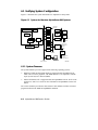
System Configuration and Setup
Verifying System Configuration .............................................................. 6-2
System Firmware .............................................................................. 6-2
Switching Between Interfaces ........................................................... 6-4
Verifying Configuration: AlphaBIOS Menu Options
for Windows NT ............................................................................... 6-5
Verifying Configuration: SRM Console Commands
for DIGITAL UNIX and OpenVMS.................................................. 6-5
CPU, Memory, and Motherboard........................................................... 6-17
CPU Daughter Board ...................................................................... 6-17
6.2.2
6.2.3
6.3
6.3.1
6.4
6.4.1
6.4.2
6.4.3
6.4.4
6.5
6.6
6.6.1
6.6.2
6.7
6.7.1
6.7.2
6.7.3
6.7.4
6.7.5
Memory Modules............................................................................ 6-17
Motherboard ................................................................................... 6-18
EISA Bus Options.................................................................................. 6-20
Identifying ISA and EISA Options.................................................. 6-20
EISA Configuration Utility .................................................................... 6-21
Before You Run the ECU ............................................................... 6-22
How to Run the ECU ...................................................................... 6-22
Configuring EISA Options.............................................................. 6-24
Configuring ISA Options ................................................................ 6-25
PCI Bus Options .................................................................................... 6-27
SCSI Bus ............................................................................................... 6-27
Configuring Internal Storage Devices ............................................. 6-28
External SCSI Expansion................................................................ 6-33
Console Port Configurations .................................................................. 6-34
set console ...................................................................................... 6-35
set tt_allow_login ........................................................................... 6-36
set tga_sync_green.......................................................................... 6-37
Setting Up a Serial Terminal to Run the AlphaBIOS Console
and the ECU ................................................................................... 6-37
Using a VGA Controller Other Than the Standard
On-Board VGA............................................................................... 6-38
Chapter 7
7.1
7.2
7.2.1
7.2.2
7.2.3
7.2.4
7.2.5
7.2.6
7.2.7
7.2.8
7.2.9
7.2.10
7.2.11
7.2.12
7.2.13
7.2.14
7.2.15
7.2.16
FRU Removal and Replacement
AlphaServer 800 FRUs ............................................................................ 7-1
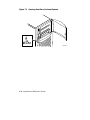
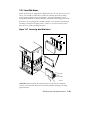
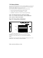
Removal and Replacement ...................................................................... 7-5
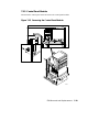
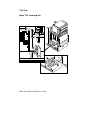
Accessing FRUs, Pedestal Systems ................................................... 7-5
Accessing FRUs, Rackmount Systems .............................................. 7-8
Cables............................................................................................. 7-11
CPU Daughter Board ...................................................................... 7-20
Control Panel Module ..................................................................... 7-21
Fan ................................................................................................. 7-22
Hard Disk Drives ............................................................................ 7-23
Memory Modules............................................................................ 7-24
Disk Status Module......................................................................... 7-26
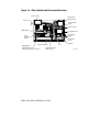
System Motherboard....................................................................... 7-27
NVRAM Chip (E14) and NVRAM TOY Clock Chip (E78) ............ 7-30
PCI/EISA Options........................................................................... 7-31
SCSI Disk Drive Backplane ............................................................ 7-32
Power Supply.................................................................................. 7-34
Speaker........................................................................................... 7-36
Removable Media........................................................................... 7-37
v
Figures
2-1
2-2
2-3
2-4
2-5
3-1
4-1
6-1
6-2
6-3
6-4
6-5
6-6
6-7
6-8
6-9
6-10
7-1
7-2
7-3
7-4
7-5
7-6
7-7
7-8
7-9
7-10
7-11
7-12
7-13
7-14
7-15
7-16
7-17
7-18
vi
AlphaBIOS Boot Menu..................................................................... 2-8
Hard Disk Drive LEDs.................................................................... 2-15
Floppy Drive Activity LED............................................................. 2-16
CD-ROM Drive Activity LED ........................................................ 2-17
Control Panel LEDs ........................................................................ 2-17
AlphaServer 800 Memory Layout ................................................... 3-12
Remote Management Console Block Diagram.................................. 4-2
System Architecture: AlphaServer 800 Systems................................ 6-2
Device Name Convention ................................................................. 6-8
Motherboard Connectors................................................................. 6-19
EISA and ISA Boards ..................................................................... 6-20
PCI Board....................................................................................... 6-27
SCSI Bus IDs.................................................................................. 6-28
RAID/SCSI Cable for Internal Disk Drive Backplane ..................... 6-30
Wide SCSI Cable for Breakouts at Rear of Enclosure ..................... 6-31
Wide SCSI Dual Connector Cable for Standard
Bulkhead Connector ...................................................................... 6-32
Removing Divider to Allow for Full-Height Device........................ 6-33
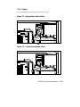
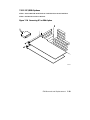
Opening Front Door, Pedestal Systems ............................................. 7-6
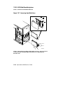
Removing Top Cover and Side Panels, Pedestal Systems.................. 7-7
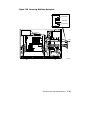
Accessing FRUs, Rackmount Systems .............................................. 7-9
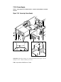
FRUs, Pedestal and Rackmount Enclosure...................................... 7-10
Floppy Drive Cable (34-Pin)........................................................... 7-11
Control Panel Module Cable ........................................................... 7-11
Power Cords ................................................................................... 7-12
Hard Disk Drive Status Cable (20-Pin)............................................ 7-14
SCSI (Embedded 16-Bit) Disk Drive Cable (68-Pin)....................... 7-15
SCSI (Embedded 8-Bit) Removable Media Cable (50-Pin) ............. 7-16
SCSI (16-Bit) RAID Option to Disk Drive Backplane (68-Pin) ....... 7-17
Wide SCSI Cable for Breakouts at Rear of Enclosure ..................... 7-18
Wide SCSI Dual Connector Cable for Standard PCI/EISA
Bulkhead Connector ....................................................................... 7-19
Removing CPU Daughter Board ..................................................... 7-20
Removing Control Panel Module .................................................... 7-21
Removing Fan ................................................................................ 7-22
Removing Hard Disk Drives ........................................................... 7-23
Memory Slots on Motherboard........................................................ 7-24
7-19
7-20
7-21
7-22
7-23
7-24
7-25
7-26
7-27
7-28
7-29
7-30
7-31
7-32
A-1
A-2
A-3
A-4
B-1
B-2
Removing DIMMs from Motherboard............................................. 7-25
Installing DIMMs on Motherboard.................................................. 7-25
Removing Disk Status Module........................................................ 7-26
Removing EISA and PCI Options ................................................... 7-27
Removing CPU Daughter Board ..................................................... 7-28
Removing Air Flow Baffle and Motherboard .................................. 7-29
Motherboard Layout ....................................................................... 7-30
Removing PCI or EISA Option ....................................................... 7-31
Removing Hard Disk Drives ........................................................... 7-32
Removing Disk Drive Backplane .................................................... 7-33
Removing Power Supply................................................................. 7-34
Removing Speaker and Its Cable .................................................... 7-36
Removing the Floppy Drive............................................................ 7-37
Removing the CD-ROM Drive........................................................ 7-38
Motherboard Jumpers (Default Settings) .......................................... A-2
AlphaServer 8005/400 and 5/333 CPU
Daughter Board (Jumper J3) ............................................................ A-4
Jumper J1 on the CPU Daughter Board ............................................ A-5
SCSI Hard Disk Backplane Jumper Settings (J5).............................. A-6
Internal Connectors...........................................................................B-2
External Connectors..........................................................................B-3
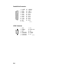
Tables
1-1
1-2
1-3
1-4
1-5
2-1
2-2
2-3
2-4
2-5
2-6
2-7
2-8
3-1
4-1
4-2
5-1
6-1
Power Problems ................................................................................ 1-3
Problems Getting to Console Mode................................................... 1-4
Problems Reported by the Console.................................................... 1-6
Boot Problems .................................................................................. 1-8
Errors Reported by the Operating System ......................................... 1-9
Interpreting Error Beep Codes .......................................................... 2-3
Console Power-Up Countdown Description and FRUs ...................... 2-6
Mass Storage Problems ................................................................... 2-11
Troubleshooting RAID Problems .................................................... 2-14
Hard Disk Drive LEDs.................................................................... 2-16
Control Panel LEDs ........................................................................ 2-18
PCI Troubleshooting....................................................................... 2-19
EISA Troubleshooting .................................................................... 2-21
Summary of Diagnostic and Related Commands............................... 3-2
Dial and Alert String Elements ......................................................... 4-6
RMC Troubleshooting .................................................................... 4-19
AlphaServer 800 Fault Detection and Connection............................. 5-2
Environment Variables Set During System Configuration............... 6-11
vii
6-2
6-3
6-4
7-1
7-2
7-3
Summary of Procedure for Configuring EISA Bus
(EISA Options Only) ...................................................................... 6-24
Summary of Procedure for for Configuring ISA Options................. 6-25
Serial Line Keyboard Commands.................................................... 6-38
AlphaServer 800 FRUs ..................................................................... 7-2
Power Cord Order Numbers (Pedestal Systems).............................. 7-13
Power Cord Order Numbers (Rackmount Systems)......................... 7-13
Appendix A
Default Jumper Settings
Appendix B
Connector Pin Layout
Index
viii
Preface
Intended Audience
This guide describes the procedures and tests used to service AlphaServer 800
systems and is intended for use by Digital Equipment Corporation service personnel
and qualified self-maintenance customers.
The material is presented as follows:
•
Chapter 1, Troubleshooting Strategy, describes the troubleshooting strategy
for AlphaServer 800 systems.
•
Chapter 2, Power-Up Diagnostics and Display, provides information on how
to interpret error beep codes and the power-up display.
•
Chapter 3, Running System Diagnostics, describes how to run ROM-based
diagnostics.
•
Chapter 4, Server Management Console, describes the use and operation of
the remote management console (RMC).
•
Chapter 5, Error Log Analysis, describes how to interpret error logs reported
to the operating system.
•
Chapter 6, System Configuration and Setup, provides configuration and setup
information for the system and system options.
•
Chapter 7, FRU Removal and Replacement, describes the field replacement
procedures for AlphaServer 800 systems.
•
Appendix A, provides the location and default settings for all jumpers in
AlphaServer 800 systems.
•
Appendix B, provides the pin layout for external and internal connectors.
ix
Conventions
The following conventions are used in this guide:
Convention
Meaning
WARNING:
A warning contains information to prevent injury.
CAUTION:
A caution contains information essential to avoid damage to
equipment or software.
NOTE:
A note calls the reader’s attention to important information.
[]
In command format descriptions, brackets indicate optional
elements.
italic type
In console command sections, italic type indicates a variable.
x
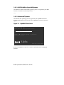
Related Documentation
Table 1 lists the documentation kits and related documentation for AlphaServer 800
systems.
Table 1 AlphaServer 800 Documentation
Title
Order Number
AlphaServer 800 System Information Kit
QZ–00XAA–GZ
AlphaServer 800 User's Guide
EK–ASV80–UG
AlphaServer 800 Basic Installation
EK–ASV80–IG
AlphaServer 800 Maintenance Kit
QZ–00XAB–GZ
AlphaServer 800 Service Guide (hard copy)
EK–ASV80–SG
Online Service Information (diskette)
AK–R2MAA–CA
AlphaServer 800 Illustrated Parts Breakdown
EK–ASV80–IP
Reference Information
DEC Verifier and Exerciser Tool User’s Guide
AA–PTTMD–TE
Guide to Kernel Debugging
AA–PS2TD–TE
OpenVMS Alpha System Dump Analyzer Manual
AA–PV6UB–TE
DECevent Translation and Reporting Utility for
OpenVMS Alpha, User and Reference Guide
AA–Q73KC–TE
DECevent Translation and Reporting Utility for
DIGITAL UNIX, User and Reference Guide
AA–QAA3A–TE
DECevent Analysis and Notification Utility for
OpenVMS Alpha, User and Reference Guide
AA–Q73LC–TE
DECevent Analysis and Notification Utility for
DIGITAL UNIX, User and Reference Guide
AA–QAA4A–TE
xi
Chapter 1
Troubleshooting Strategy
This chapter describes the troubleshooting strategy for AlphaServer 800 systems.
•
Questions to consider before you begin troubleshooting
•
Diagnostics flows for each problem category
•
List of service tools and utilities
•
List of information services
1.1 Questions to Consider
Before troubleshooting any system problem, first check the site maintenance log for
the system's service history. Be sure to ask the system manager the following
questions:
•
Has the system been used and did it work correctly?
•
Have changes to hardware or updates to firmware or software been made to the
system recently? If so, are the revision numbers compatible for the system?
(Refer to the hardware and operating system release notes).
•
What is the state of the system? Is the operating system running?
If the operating system is down and you are not able to bring it up, use the
diagnostic beep codes and console environment diagnostic tools, such as the
power-up display on the VGA terminal and ROM-based diagnostics (RBDs).
If the operating system is running, use the operating system environment
diagnostic tools, such as the DECevent management utility (to translate and
interpret error logs), crash dumps, and exercisers (DEC VET).
Troubleshooting Strategy
1-1
1.2 Problem Categories
System problems can be classified into the following five categories. Using these
categories, you can quickly determine a starting point for diagnosis and eliminate the
unlikely sources of the problem.
1.
Power problems (Table 1-1)
2.
No access to console mode (Table 1-2)
3.
Console-reported failures (Table 1-3)
4.
Boot failures (Table 1-4)
5.
Operating system-reported failures (Table 1-5)
1-2
AlphaServer 800 Service Guide
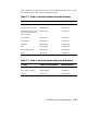
Table 1-1 Power Problems
Symptom
Action
System does not power on.
•
Check the power source and power cord.
•
Check the On/Off setting on the operator
control panel. Toggle the On/Off button to
off, then back to the On position to clear a
remote power disable.
•
Check the indicator lights on the operator
control panel. If the green Power OK light is
off and amber Halt/Remote Power Off light is
on, the system may be powered off by one of
the following:
Power supply shuts down after
a few seconds (fan failure).
−
a remote management console command
−
system software
−
fan failure
−
overtemperature condition
−
power supply failure
−
power select switch on power supply is
set to 120V for a 220V power source
•
Check that the ambient room temperature is
within environmental specifications
(10–40°C, 50–104°F).
•
Check that internal power supply cables are
plugged in at the system motherboard.
Listen to hear if the fan is spinning at power-up. A
failure of the fan causes the system to shut down
after a few seconds.
Enter the remote management console and query
system status/alerts (using the status command)
for an indication of fan failure or overtemperature
condition. Refer to Chapter 4 for instructions.
Troubleshooting Strategy
1-3
Table 1-2 Problems Getting to Console Mode
Symptom
Action
Power-up screen is not
displayed.
Interpret the error beep codes at power-up (Section 2.1)
for a failure detected during self-tests.
Check that the keyboard and monitor are properly
connected and turned on.
If the power-up screen is not displayed, yet the system
enters console mode when you press the Return key,
check that the console environment variable is set
correctly.
If you are using a VGA monitor as the console
terminal, the console variable should be set to
graphics. If you are using a serial console terminal, the
console environment variable should be set to serial.
If you are using the standard onboard VGA controller,
the VGA enable (J27) jumper on the motherboard must
be enabled. Refer to Appendix A.
If a VGA controller other than the standard on-board
VGA controller is being used, refer to Section 6.7 for
more information.
If console is set to serial, the power-up screen is routed
to the COM1 serial communication port (Section 6.7)
and cannot be viewed from the VGA monitor.
1-4
AlphaServer 800 Service Guide
Table 1-2 Problems Getting to Console Mode (continued)
Symptom
Action
Try connecting a console terminal to the COM1 serial
communication port (Section 6.7). Check the baud rate
setting for the console terminal and the system. The
system baud rate setting is 9600. When using the
COM1 port, you must set the console environment
variable to serial.
If none of the above considerations solve the problem,
check that the J1 jumper on the CPU daughter board is
not missing. Refer to Appendix A for the standard boot
setting.
If the system has a customized NVRAM file, try
powering up or resetting the system with the Halt
button set to the “In” position. The NVRAM script will
not be executed when powering up or resetting the
system with the Halt button depressed.
For certain situations, power up using the fail-safe
loader (Section 2.8) to load new console firmware from
a diskette.
Troubleshooting Strategy
1-5
Table 1-3 Problems Reported by the Console
Symptom
Action
Power-up tests do not complete.
Interpret the error beep codes at power-up
(Section 2.1) and check the power-up screen
(Section 2.2) for a failure detected during selftests.
The system attempts to boot from
the floppy drive after a checksum
error is reported (error beep code
1-1-2 or 1-1-4).
Reinstall firmware by inserting a fail-safe loader
diskette. Refer to the procedure provided with
the firmware update documentation.
Console program reports error:
Use the error beep codes (Section 2.1) and/or
console terminal (Section 2.2) to determine the
error.
•
Error beep codes report an
error at power-up.
•
Power-up screen includes
error messages.
Examine the console event log (enter the more
el command) or the power-up screen (Section
2.2) to check for errors detected during powerup.
•
Power-up screen or console
event log indicates problems
with mass storage devices.
Use the troubleshooting tables in Section 2.3 to
determine the problem.
•
Storage devices are missing
from the show config
display.
Use the troubleshooting tables in Section 2.3 to
determine the problem.
•
Power-up screen or console
event log indicates problems
with EISA devices.
Use the troubleshooting tables in Section 2.6 to
determine the problem.
•
PCI devices are missing from
the show config display.
Use the troubleshooting tables in Section 2.6 to
determine the problem.
1-6
AlphaServer 800 Service Guide
Table 1-3
Problems Reported by the Console (continued)
Symptom
Action
•
Power-up screen or console
event log indicates problems
with EISA devices.
Use the troubleshooting table in Section 2.7 to
determine the problem.
•
EISA devices are missing
from the show config
display.
Use the troubleshooting table in Section 2.7 to
determine the problem.
Run the ROM-based diagnostic (RBD) tests
(Chapter 3) to verify the problem.
Troubleshooting Strategy
1-7
Table 1-4 Boot Problems
Symptom
Action
System cannot find boot
device.
Check the system configuration for the correct device
parameters (node ID, device name, and so on).
•
For DIGITAL UNIX and OpenVMS, use the show
config and show device commands (Section 6.1.4).
•
For Windows NT, use the AlphaBIOS menus to
examine and set the system configuration (Section
6.1.3).
Check the system configuration for the correct
environment variable settings.
•
For DIGITAL UNIX and OpenVMS, examine the
auto_action, bootdef_dev, boot_osflags, and
os_type environment variables (Section 6.1.4.4).
For problems booting over a network, check the
ew*0_protocols environment variable settings:
Systems booting from a DIGITAL UNIX server
should be set to bootp; systems booting from an
OpenVMS server should be set to mop (Section
6.1.4.4).
•
Device does not boot.
For Windows NT, examine the Auto Start and
Auto Start Count CMOS Setup Menu Options.
For problems booting over a network, check the
ew*0_protocols environment variable settings:
Systems booting from a DIGITAL UNIX server should
be set to bootp; systems booting from an OpenVMS
server should be set to mop (Section 6.1.4.4).
Run the device tests (Chapter 3) to check that the boot
device is operating.
1-8
AlphaServer 800 Service Guide
Table 1-5 Errors Reported by the Operating System
Symptom
Action
System is hung or has crashed.
Press the Halt button and enter the crash
command to provide a crash dump file for
analysis.
Refer to OpenVMS Alpha System Dump Analyzer
Utility Manual for information on how to interpret
OpenVMS crash dump files.
Refer to the Guide to Kernel Debugging for
information on using the DIGITAL UNIX Krash
Utility.
Errors have been logged and
the operating system is up.
Examine the operating system error log files to
isolate the problem (Chapter 5).
If the problem occurs intermittently, run an
operating system exerciser, such as DEC VET, to
stress the system.
Refer to the DEC Verifier and Exerciser Tool
User's Guide for instructions on running DEC
VET.
Troubleshooting Strategy
1-9
1.3 Service Tools and Utilities
This section lists the tools and utilities available for acceptance testing, diagnosis,
and serviceability and provides recommendations for their use.
Error Handling/Logging Tools (DECevent)
DIGITAL UNIX, OpenVMS, and Microsoft Windows NT operating systems
provide recovery from errors, fault handling, and event logging.
The DECevent Translation and Reporting Utility provides bit-to-text translation
of event logs for interpretation for DIGITAL UNIX and OpenVMS error logs.
RECOMMENDED USE: Analysis of error logs is the primary method of
diagnosis and fault isolation. If the system is up, or you are able to bring it up,
look at this information first.
ROM-Based Diagnostics (RBDs)
Many ROM-based diagnostics and exercisers execute automatically at power-up
and can be invoked in console mode using console commands.
RECOMMENDED USE: ROM-based diagnostics are the primary means of
testing the console environment and diagnosing the CPU, memory, Ethernet, I/O
buses, and SCSI and DSSI subsystems. Use ROM-based diagnostics in the
acceptance test procedures when you install a system, add a memory module, or
replace the following components: CPU module, memory module, motherboard,
I/O bus device, or storage device. Refer to Chapter 3 for information on running
ROM-based diagnostics.
Loopback Tests
Internal and external loopback tests are used to isolate a failure by testing
segments of a particular control or data path. The loopback tests are a subset of
the ROM-based diagnostics.
RECOMMENDED USE: Use loopback tests to isolate problems with the COM2
serial port, the parallel port, and Ethernet controllers. Refer to Chapter 3 for
instructions on performing loopback tests.
1-10
AlphaServer 800 Service Guide
Firmware Console Commands
Console commands are used to set and examine environment variables and device
parameters, as well as to invoke ROM-based diagnostics and exercisers. For
example, the show memory, show configuration, and show device commands
are used to examine the configuration; the set bootdef_dev, set auto_action, and
set boot_osflags commands are used to set environment variables; and the cdp
command is used to configure DSSI parameters.
RECOMMENDED USE: Use console commands to set and examine environment
variables and device parameters and to run RBDs. Refer to Chapter 6 for
information on configuration-related firmware commands and Chapter 3 for
information on running RBDs.
Operating System Exercisers (DEC VET)
The DIGITAL Verifier and Exerciser Tool (DEC VET) is supported by the
DIGITAL UNIX, OpenVMS, and Windows NT operating systems. DEC VET
performs exerciser-oriented maintenance testing of both hardware and operating
systems.
RECOMMENDED USE: Use DEC VET as part of acceptance testing to ensure
that the CPU, memory, disk, tape, file system, and network are interacting
properly. Also use DEC VET to stress test the user's environment and
configuration by simulating system operation under heavy loads to diagnose
intermittent system failures.
Crash Dumps
For fatal errors, such as fatal bugchecks, the DIGITAL UNIX and OpenVMS
operating systems will save the contents of memory to a crash dump file.
RECOMMENDED USE: Crash dump files can be used to determine why the
system crashed. To save a crash dump file for analysis, you need to know the
proper system settings. Refer to the OpenVMS Alpha System Dump Analyzer
Utility Manual or the Guide to Kernel Debugging for DIGITAL UNIX.
Troubleshooting Strategy
1-11
1.4 Information Services
Several information resources are available, including online information for service
providers and customers, computer-based training, and maintenance documentation
database services. A brief description of some of these resources follows.
Service Help File
The information contained in this guide, including the field-replaceable unit
(FRU) procedures and illustrations, is available in online format. You can
download the hypertext file (AS800.HLP) or order a self-extracting .HLP on
diskette (AK–R2MAA–CA) or the AlphaServer 800 Maintenance Kit
(QZ–00XAB–GZ). The maintenance kit includes hardcopy service guide,
diskette, and illustrated parts breakdown.
Alpha Firmware Updates
Under certain circumstances, such as a CPU upgrade or replacement of the system
motherboard, you may need to update your system firmware. An Alpha Firmware
CD-ROM is available with DIGITAL UNIX, OpenVMS, and Windows NT
operating systems. Operating system and firmware revisions must be compatible.
The Alpha firmware files can also be downloaded from the Internet as follows:
ftp://ftp.digital.com/pub/Digital/Alpha/firmware/readme.html
The above README file describes the firmware directory structure, and how the
files can be downloaded and used.
New versions of firmware released between shipments of the Alpha Firmware
CD-ROM are available in an interim directory:
ftp://ftp.digital.com/pub/Digital/Alpha/firmware/interim/
Fail-Safe Floppy Loader
The fail-safe floppy loader diskette (AK-R4VLA-CA) can be ordered. Call 1800-DIGITAL, or download the firmware from the Internet (using the firmware
update address above) to create your own fail-safe loader diskette.
1-12
AlphaServer 800 Service Guide
ECU Revisions
The EISA Configuration Utility (ECU) is used for configuring EISA options on
AlphaServer systems. Systems are shipped with an ECU kit, which includes the
ECU license. Customers who already have the ECU and license, but need the
latest ECU revision (a minimum revision of 1.10 for AlphaServer 800 systems),
can order a separate kit. Call 1-800-DIGITAL to order.
If the customer plans to migrate from DIGITAL UNIX or OpenVMS to Windows
NT, you must re-run the appropriate ECU. Failure to run the operating-specific
ECU will result in system failure.
OpenVMS Patches
Software patches for the OpenVMS operating system are available from the
World Wide Web as follows:
http://www.service.digital.com/html/patch_service.html
Choose the “Contract Access” option if you have a valid software contract with
DIGITAL or you wish to become a software contract customer. Choose the
“Public Access” options if you do not have a software service contract.
Late-Breaking Technical Information
You can download up-to-date files and late-breaking technical information
from the Internet.
The information includes firmware updates, the latest configuration utilities,
software patches, lists of supported options, wide SCSI information, and more.
FTP address:
ftp.digital.com
cd /pub/Digital/Alpha/systems/as800/
World Wide Web address:
http://www.digital.com/info/alphaserver/tech_docs/alphasrv800/
Troubleshooting Strategy
1-13
Supported Options
A list of options supported on AlphaServer 800 systems is available on the
Internet:
FTP address:
ftp://ftp.digital.com/pub/Digital/Alpha/systems/as800/
World Wide Web address:
http://www.digital.com/info/alphaserver/tech_docs/alphasrv800/
You can obtain information about hardware configurations for the AlphaServer
800 from the DIGITAL Systems and Options Catalog. The catalog can be used to
order and configure systems and hardware options. The catalog presents all
products that are announced, actively marketed, and available for ordering.
Access printable postscript files of any section of the catalog from the Internet as
follows (be sure to check the Readme file):
ftp://ftp.digital.com/pub/Digital/info/SOC/
Training
The following computer-based training (CBT) and lecture lab courses are
available:
•
•
•
•
•
Alpha Concepts
DSSI Concepts: EY-9823E
ISA and EISA Bus Concepts: EY-I113E-P0
RAID Concepts: EY-N935E
SCSI Concepts and Troubleshooting: EY-P841E, EY-N838E
DIGITAL Assisted Services
DIGITAL Assisted Services (DAS) offers products, services, and programs to
customers who participate in the maintenance of DIGITAL computer equipment.
Components of DIGITAL Assisted Services include:
•
•
•
•
1-14
Spare parts and kits
Diagnostics and service information/documentation
Tools and test equipment
Parts repair services, including field change orders
AlphaServer 800 Service Guide
Chapter 2
Power-Up Diagnostics and Display
This chapter provides information on how to interpret error beep codes and the
power-up display on the console screen. In addition, a description of the power-up
and firmware power-up diagnostics is provided as a resource to aid in
troubleshooting.
•
Section 2.1 describes how to interpret error beep codes at power-up.
•
Section 2.2 describes how to interpret the power-up screen display.
•
Section 2.3 describes how to troubleshoot mass-storage problems indicated at
power-up or storage devices missing from the show config display.
•
Section 2.4 shows the location of storage device LEDs.
•
Section 2.5 describes the control panel LEDs.
•
Section 2.6 describes how to troubleshoot PCI bus problems indicated at powerup or PCI devices missing from the show config display.
•
Section 2.7 describes how to troubleshoot EISA bus problems indicated at
power-up or EISA devices missing from the show config display.
•
Section 2.8 describes the use of the fail-safe loader.
•
Section 2.9 describes the power-up sequence.
•
Section 2.10 describes firmware power-up diagnostics.
Power-Up Diagnostics and Display
2-1
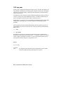
2.1 Interpreting Error Beep Codes
If errors are detected at power-up, audible beep codes are emitted from the system.
For example, if the SROM code could not find any good memory, you would hear a
1-3-3 beep code (one beep, a pause, a burst of three beeps, a pause, and another burst
of three beeps).
Be sure to check that the CPU daughter board is properly seated in its connector if
errors are reported.
NOTE: A single beep is emitted when the SROM code completes successfully. The
console firmware then continues with its power-up tests.
The beep codes are the primary diagnostic tool for troubleshooting problems when
console mode cannot be accessed. Refer to Table 2-1 for information on interpreting
error beep codes.
2-2
AlphaServer 800 Service Guide
Table 2-1 Interpreting Error Beep Codes
Beep
Code
Problem
Corrective Action
1
A single beep is emitted when
the SROM code has successfully
completed.
Not applicable. No error.
1-3
VGA monitor is not plugged in.
Plug in the graphics monitor.
If you do not want the graphics
monitor, disable the VGA jumper
(J27) on the motherboard. Refer to
Appendix A.
1-1-2
ROM data path error detected
while loading AlphaBIOS/SRM
console code.
System automatically attempts to
boot a fail-safe loader diskette
from the floppy drive.
1-1-4
The SROM code is unable to
load the console code: Flash
ROM header area or checksum
error detected.
System automatically attempts to
boot a fail-safe loader diskette
from the floppy drive.
Insert the fail-safe loader diskette
into the floppy drive to load new
AlphaBIOS/SRM console code
(Section 2.8).
If loading new console firmware
does not solve the problem, replace
the motherboard (Chapter 7).
Insert the fail-safe loader diskette
into the floppy drive to load new
console code (Section 2.8).
If loading new console firmware
does not solve the problem, replace
the motherboard (Chapter 7).
1-1-7
Floppy read error. System could
not locate a valid boot block on
the diskette.
Make sure floppy diskette is
inserted, or try another diskette.
1-2-1
TOY NVRAM failure.
Replace the TOY NVRAM chip
(E78) on system motherboard
(Chapter 7).
Continued on next page
Power-Up Diagnostics and Display
2-3
Table 2-1 Interpreting Error Beep Codes (continued)
Beep
Code
Problem
Corrective Action
1-2-4
Backup cache error.
Replace the CPU daughter board
(Chapter 7).
The system can be operated with
the B-cache disabled until a
replacement CPU daughter board is
available. Bank 1 of the J1 jumper
on the CPU daughter board is used
to disable the B-cache. Refer to
Appendix A.
1-3-3
No usable memory detected.
Verify that the memory modules are
properly seated and try powering up
again.
Swap memory with known good
memory and power up.
If populating with known good
memory does not solve the
problem, replace the CPU daughter
board (Chapter 7).
If replacing the CPU daughter board
does not solve the problem, replace
the motherboard (Chapter 7).
3-3-1
3-3-3
2-4
Generic system failure. Possible
problem sources include the
TOY NVRAM chip (Dallas
DS1287A) or PCI-to-EISA
bridge chipset (Intel 82375EB).
Replace the TOY NVRAM chip
(E78) on system motherboard
(Chapter 7).
Failure of the native SCSI
controller (Qlogic) on the system
motherboard.
Replace the motherboard
(Chapter 7).
AlphaServer 800 Service Guide
If replacing the TOY NVRAM chip
does not solve the problem, replace
the motherboard (Chapter 7).
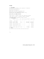
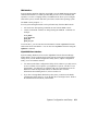
2.2 Power-Up Display
During power-up self-tests, test status and results are displayed on the console
terminal. Information similar to that in Example 2-1 is displayed on the screen.
Example 2-1 Sample Power-Up Display
ff.fe.fd.fc.fb.fa.f9.f8.f7.f6.f5.ef.df.ee.f4.
probing hose 0, PCI
probing PCI-to-EISA bridge, bus 1
bus 0, slot 5 -- pka -- QLogic ISP1020
bus 0, slot 6 -- vga -- S3 Trio64/Trio32
bus 1, slot 1 -- ewa -- DE425
bus 0, slot 11 -- ewb -- DECchip 21040-AA
bus 0, slot 13 -- ewc -- DECchip 21040-AA
ed.ec.eb.....ea.e9.e8.e7.e6.e5.e4.e3.e2.e1.e0.
T4.7-72, built on Oct 22 1997 at 17:47:16
Memory Testing and Configuration Status
64 Meg of System Memory
Bank 0 = 64 Mbytes(16 MB Per DIMM) Starting at
0x00000000
Bank 1 = No Memory Detected
Testing the System
Testing the Disks (read only)
Testing the Network
Change mode to Internal loopback.
Change to Normal Operating Mode.
Change mode to Internal loopback.
Change to Normal Operating Mode.
Change mode to Internal loopback.
Change to Normal Operating Mode.
>>>
Power-Up Diagnostics and Display
2-5
Table 2-2 provides a description of the power-up countdown for output to the serial
console port. If the power-up display stops, use the beep codes (Table 2-1 and
Table 2-2) to isolate the likely field-replaceable unit (FRU).
Table 2-2 Console Power-Up Countdown Description and FRUs
Countdown
Number
Description
Likely FRU
ff
Console initialization started
Non-specific/Status message
fe
Initialized idle PCB
Non-specific/Status message
fd
Initializing semaphores
Non-specific/Status message
fc,fb,fa
Initializing heap
Non-specific/Status message
f9
Initializing driver structures
Non-specific/Status message
f8
Initializing idle process PID
Non-specific/Status message
f7
Initializing file system
NVRAM TOY chip (E78)
f6
Initializing timer data
structures
Non-specific/Status message
f5
Lowering IPL
Non-specific/Status message
f4
Entering idle loop
NVRAM TOY chip (E78)
ef
Start memory configuration
(heap)
DIMM memory or backplane
df
Configure PCI and EISA bus
PCI or EISA bridge chips
ee
Start phase 1 drivers:
NVRAM driver. Probe EISA
and PCI bus for option
modules.
NVRAM chip (E14), PCI or
EISA option
ed
Start phase 2 drivers:
Non-specific/Status message
ec
Start phase 3 drivers (console
select): tt serial line class,
TGA graphics, VGA
graphics, and keyboard
drivers
Keyboard, VGA or TGA
option, or backplane
eb
Run power-up memory test
DIMM memory
2-6
AlphaServer 800 Service Guide
Table 2-2 Console Power-Up Countdown Description
and FRUs (continued)
Countdown
Number
Description
Likely FRU
ea
Start phase 4 drivers: console
support drivers.
Non-specific/Status message
e9
Build HWRPB CPU
information
Non-specific/Status message
e8
Initialize environment
variables
Non-specific/Status message
e7
Start SCSI class driver
Backplane (onboard Qlogic)
e6
Start phase 5 drivers: I/O
drivers
PCI or EISA option
e5
Restore timers
NVRAM TOY chip (E78)
Power-Up Diagnostics and Display
2-7
2.2.1.1 DIGITAL UNIX or OpenVMS Systems
The DIGITAL UNIX and OpenVMS operating systems are supported by the SRM
firmware. The SRM console prompt follows:
>>>
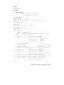
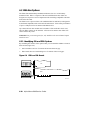
2.2.1.2 Windows NT Systems
The Windows NT operating system is supported by the AlphaBIOS firmware.
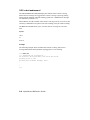
Systems using Windows NT power up to the AlphaBIOS boot menu as shown in
Figure 2-1.
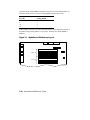
Figure 2-1 AlphaBIOS Boot Menu
AlphaBIOS Version 5.26
Please select the operating system to start:
Windows NT Server 4.00
Use
and
to move the highlight to your choice.
Press Enter to choose.
Alpha
Press <F2> to enter SETUP
PK-0728A-96
Refer to the AlphaServer 800 User’s Guide for information on the AlphaBIOS
firmware.
2-8
AlphaServer 800 Service Guide
2.2.2 Console Event Log
A console event log consists of status messages received during power-up self-tests.
If problems occur during power-up, standard error messages indicated by asterisks
(***) may be embedded in the console event log. To display a console event log, use
the more el or cat el command.
NOTE: To stop the screen display from scrolling, press Ctrl/S. To resume scrolling,
press Ctrl/Q.
You can also use the more el command to display the console event log
one screen at a time.
Example 2-2 shows a console event log that contains two standard error messages.
Indicates that the mouse is not plugged in or is not working.
Indicates that SROM tests detected a bad DIMM (bank 1, DIMM 3).
Example 2-2 Sample Console Event Log
>>> cat el
ff.fe.fd.fc.fb.fa.f9.f8.f7.f6.f5.ef.df.ee.f4.
probing hose 0, PCI
probing PCI-to-EISA bridge, bus 1
bus 0, slot 5 -- pka -- QLogic ISP1020
bus 0, slot 6 -- vga -- S3 Trio64/Trio32
bus 1, slot 1 -- ewa -- DECchip 21040-AA
bus 0, slot 11 -- ewb -- DECchip 21040-AA
bus 0, slot 13 -- ewc -- DECchip 21040-AA
ed.ec.
** mouse error **
*** Bad memory detected by serial rom
*** SROM failing Bank 1, DIMM 3
eb.....ea.e9.e8.e7.e6.resetting the SCSI bus on
pka0.7.0.5.0 e5.e4.e3.e2.e1.e0.
>>>
Power-Up Diagnostics and Display
2-9
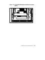
2.3 Mass Storage Problems
Mass storage failures at power-up are usually indicated by read fail messages. Other
problems are indicated by storage devices missing from the show config display.
•
Table 2-3 provides information for troubleshooting mass storage problems
indicated at power-up or storage devices missing from the show config display.
•
Table 2-4 provides troubleshooting tips for AlphaServer systems that use a
RAID array subsystem.
•
Section 2.4 provides information on storage device LEDs.
Use Table 2-3 and Table 2-4 to diagnose the likely cause of the problem.
2-10
AlphaServer 800 Service Guide
Table 2-3 Mass Storage Problems
Symptom
Problem
Corrective Action
Drives are missing
from the show
config display.
Drives have
duplicate SCSI IDs.
Correct SCSI IDs.
SCSI bus not
properly
terminated.
Check the following jumpers and
terminator to ensure that proper
termination is provided for all
internal SCSI devices.
Note: Internal hard disk drives are
automatically assigned SCSI IDs 0,
1, 2, and 3 (from left to right for
pedestal systems; and bottom to top
for rackmount systems). The
onboard controller is assigned SCSI
ID 7, and the CD-ROM, SCSI ID 4.
•
The SCSI terminator jumper
(J51) on the system
motherboard should be set to
“on.” Refer to Appendix A.
•
The J5 jumper on the hard disk
drive backplane should be set
as shown in Appendix A.
•
The cable terminator at the end
of the SCSI removable media
cable should be properly
seated.
For controllers other than the
onboard controller, the
pk*0_soft_term environment
variable is used to enable/disable
SCSI terminators. Refer to
Table 6-1.
Continued on next page
Power-Up Diagnostics and Display
2-11
Table 2-3 Mass Storage Problems (continued)
Symptom
Problem
Corrective Action
Drives are missing
from the show
config display/One
drive appears seven
times on the show
config display.
Drive SCSI ID set
to 7 (reserved for
host ID)
Correct SCSI IDs.
Duplicate host IDs
on a shared bus.
Change host ID by setting the
pk*0_host_id environment variable
(set pk*0_host_id) through the
SRM console.
LEDs do not come
on. Drive missing
from the show
config display.
Missing or loose
cables.
Remove device and inspect cable
connections.
Drives not properly
seated on the hard
disk backplane.
Reseat drive.
Drives disappear
intermittently from
the show config
and show device
displays.
SCSI bus length
exceeded.
The entire SCSI bus length, from
terminator to terminator, must not
exceed 6 meters for fast doubleended SCSI-2, or 3 meters for fast
single-ended SCSI-2.
2-12
or
AlphaServer 800 Service Guide
or
Table 2-3 Mass Storage Problems (continued)
Symptom
Problem
Corrective Action
Read/write errors
in the console
event log; storage
adapter port fails.
Terminator
missing or
wrong
terminator
used.
Check the following jumpers and
terminator to ensure that proper
termination is provided for all internal
SCSI devices.
•
The SCSI terminator jumper (J51)
on the system motherboard should
be set to “on.” Refer to Appendix A.
•
The J5 jumper on the hard disk drive
backplane should be set as shown in
Appendix A.
•
The cable terminator at the end of
the SCSI removable media cable
should be properly seated.
For controllers other than the onboard
controller, the pk*0_soft_term
environment variable is used to
enable/disable SCSI terminators. Refer
to Table 6-1.
Devices produce
errors or device
IDs are dropped.
Extra
terminator.
Check that bus is terminated only at
beginning and end. Remove unnecessary
terminators.
Removable media devices should disable
termination (check device jumpers or
SIPs).
For controllers other than the onboard
controller, the pk*0_soft_term
environment variable is used to
enable/disable SCSI terminators. Refer
to Table 6-1.
Problems persist
after eliminating
the problem
sources.
SCSI storage
controller
failure.
Replace failing EISA or PCI storage
adapter module (or motherboard for the
native SCSI controller).
Power-Up Diagnostics and Display
2-13
Table 2-4 provides troubleshooting hints for systems with a StorageWorks RAID
array subsystem.
Table 2-4 Troubleshooting RAID Problems
Symptom
Action
Some RAID drives do not
appear on the show device d
display.
Valid configured RAID logical drives will appear
as DRA0--DRAn, not as DKn. Configure the
drives by running the RAID Configuration Utility
(RCU), following the instructions provided with
the StorageWorks RAID array subsystem.
Reminder: several physical disks can be grouped
as a single logical DRAn device.
Drives on the SWXCR
controller power up with the
amber Fault light on.
Whenever you move drives onto or off of the
controller, run the RAID Configuration Utility to
set up the drives and logical units. Follow the
instructions provided with the StorageWorks
RAID array subsystem.
Cannot access disks
connected to the RAID
subsystem on Windows NT
systems.
On Windows NT systems, disks connected to the
controller must be spun up before they can be
accessed.
2-14
While running the ECU, verify that the controller
is set to spin up two disks every 6 seconds. This
is the default setting if you are using the default
configuration files for the controller. If the
settings are different, adjust them as needed.
AlphaServer 800 Service Guide
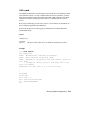
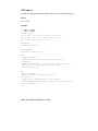
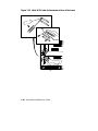
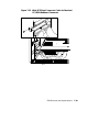
2.4 Storage Device LEDs
Storage device LEDs indicate the status of the device.
•
Figure 2-2 shows the hard disk drive LEDs for disk drives in the system
enclosure.
•
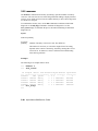
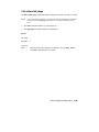
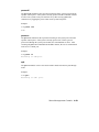
Figure 2-3 shows the Activity LED for the floppy drive. This LED is on when
the drive is in use.
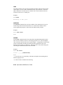
•
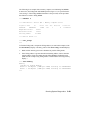
Figure 2-4 shows the Activity LED for the CD-ROM drive. This LED is on
when the drive is in use.
For information on other storage devices, refer to the documentation provided by the
manufacturer or vendor.
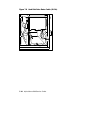
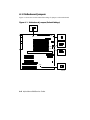
Figure 2-2 Hard Disk Drive LEDs
ALPHA SERVER 800
5/400
Activity
Fault
Disk Present
Disk Present
Fault
Activity
IP00080A
Power-Up Diagnostics and Display
2-15
Table 2-5 Hard Disk Drive LEDs
LED
Meaning
Activity (green)
Fault (amber)
When lit, indicates disk activity.
Disk Present
(green)
When lit indicates that a disk drive is installed for that position
in the hard disk drive backplane.
At product introduction, this LED has no function, it may be
used with future enhancements.
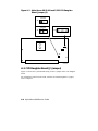
Figure 2-3 Floppy Drive Activity LED
Activity LED
IP00081
2-16
AlphaServer 800 Service Guide
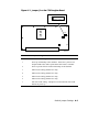
Figure 2-4 CD-ROM Drive Activity LED
Activity LED
IP00082
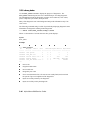
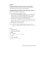
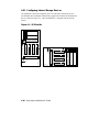
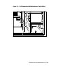
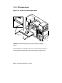
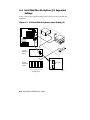
2.5 Control Panel LEDs
Control panel LEDs (Figure 2-5) indicate the status of the system. Table 2-6
describes the LEDs.
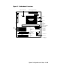
Figure 2-5 Control Panel LEDs
Power
Halt
Reset
Reset
Halt
Power
IP00039B
Power-Up Diagnostics and Display
2-17
Table 2-6 Control Panel LEDs
Power OK
(green)
Halt
(amber)
Off
Off
System powered-off using control panel Power button
or no AC power is present.
Off
On
System power is enabled using the control panel
Power button, but the system has been powered off by
one of the following:
• Remote management console command
Status
•
System software
•
Fan failure
•
Overtemperature condition
•
Power supply failure
On
Off
System is powered-on and is not in a halt state.
On
On
System is powered-on and the Halt button is pressed
or a halt in command has been issued at the remote
management console.
NOTE: To power up or reset without executing the NVRAM script or initiating an
automatic operating system boot, power up or reset with the Halt button
depressed.
2-18
AlphaServer 800 Service Guide
2.6 PCI Bus Problems
PCI bus failures at power-up are usually indicated by the inability of the system to
see the device. Table 2-7 provides steps for troubleshooting PCI bus problems. Use
the table to diagnose the likely cause of the problem.
NOTE: Some PCI devices do not implement PCI parity, and some have a paritygenerating scheme in which parity is sometimes incorrect or is not
compliant with the PCI Specification. In such cases, the device functions
properly as long as parity is not checked.
The pci_parity environment variable for the SRM console, or the PCI Parity
Checking option on the Advanced CMOS Setup Menu for the AlphaBIOS
console, allow you to turn off parity checking so that false PCI parity errors
do not result in machine check errors.
When you disable PCI parity, no parity checking is implemented for any
PCI device. The default setting is off, no parity checking.
Table 2-7 PCI Troubleshooting
Step
Action
1
Confirm that the PCI module and cabling are properly seated.
2
Run ROM-based diagnostics for the type of option:
•
Storage adapter—Run test to exercise the storage devices off
the PCI controller option (Chapter 3).
•
Ethernet adapter—Run test to exercise an Ethernet adapter
(Chapter 3).
3
Check for a bad slot by moving the last installed controller to a
different slot.
4
Call the option manufacturer or support for help.
Power-Up Diagnostics and Display
2-19
2.7 EISA Bus Problems
EISA bus failures at power-up may be indicated by the following messages:
EISA Configuration Error. Run the EISA Configuration
Utility.
Run the EISA Configuration Utility (ECU) when this message is displayed. Other
EISA bus problems are indicated by the absence of EISA devices from the show
config display.
Table 2-8 provides steps for troubleshooting EISA bus problems that persist after
you run the ECU.
2-20
AlphaServer 800 Service Guide
Table 2-8 EISA Troubleshooting
Step
Action
1
Confirm that the EISA module and any cabling are properly seated.
2
Run the ECU to:
•
Confirm that the system has been configured with the most
recently installed controller.
•
See what the hardware jumper and switch setting should be for
each ISA controller.
•
See what the software setting should be for each ISA and EISA
controller.
•
See if the ECU deactivated (<>) any controllers to prevent
conflict.
See if any controllers are locked (!), which limits the ECU's
ability to change resource assignments.
•
3
Confirm that the hardware jumpers and switches on ISA controllers
reflect the settings indicated by the ECU. Start with the last ISA
module installed.
4
Run ROM-based diagnostics for the type of option:
•
Storage adapter—Run test to exercise the storage devices off
the EISA controller option (Chapter 3).
•
Ethernet adapter—Run test to exercise an Ethernet adapter
(Chapter 3).
5
Check for a bad slot by moving the last installed controller to a
different slot.
6
Call the option manufacturer or support for help.
Power-Up Diagnostics and Display
2-21
Additional EISA Troubleshooting Tips
The following tips can aid in isolating EISA bus problems:
•
Peripheral device controllers need to be seated firmly in their slots to make all
necessary contacts. Improper seating is a common source of problems.
•
Be sure you run the correct version of the ECU for the operating system. For
Windows NT, use ECU diskette DECpc AXP (AK-PYCJ*-CA); for DIGITAL
UNIX and OpenVMS, use ECU diskette DECpc AXP (AK-Q2CR*-CA).
The CFG files supplied with the option you want to install may not work on
AlphaServer 800 systems. Some CFG files call overlay files that are not required
on this system or may reference inappropriate system resources, for example,
BIOS addresses. Contact the option vendor to obtain the proper CFG file.
•
Peripherals cannot share direct memory access (DMA) channels. Assignment of
more than one peripheral to the same DMA channel can cause unpredictable
results or even loss of function of the EISA module.
•
Not all EISA products work together. EISA is an open standard, and not every
EISA product or combination of products can be tested. Violations of
specifications may matter in some configurations, but not in others.
Manufacturers of EISA options may have a list of ISA and EISA options that do
not function in combination with particular systems. Be sure to check the
documentation or contact the option vendor for the most up-to-date information.
•
EISA options will not function unless they are first configured using the ECU.
•
The ECU will not notify you if the configuration program diskette is writeprotected when it attempts to write the system configuration file (system.sci) to
the diskette.
2-22
AlphaServer 800 Service Guide
2.8 Fail-Safe Loader
The fail-safe loader (FSL) allows you to boot an SRM console from a diskette at
power-up. This allows you to power up without running power-up diagnostics and
load new SRM and FSL console firmware from the firmware diskette.
NOTE: The fail-safe loader should be used only when a failure at power-up
prohibits you from getting to the console program. You cannot boot an
operating system from the fail-safe loader.
If a checksum error is detected when the console is loading at power-up
(error beep code 1-1-2 or 1-1-4), the fail-safe loader is automatically
activated so that you can reinstall the firmware.
The fail-safe loader (FSL) allows you to attempt to recover when one of the
following is the cause of a problem getting to the console program under normal
power-up:
•
A hardware or power failure, or accidental power-down during a firmware
upgrade occurred.
•
A configuration error, such as an incorrect environment variable setting or an
inappropriate NVRAM script.
•
A driver error at power-up.
•
A checksum error is detected when the SRM console is loading at power-up
(corrupted firmware).
The fail-safe loader program is available on diskette (AK-R4VLA-CA), or it can be
downloaded from the Internet to create your own diskette.
http://ftp.digital.com/pub/Digital/Alpha/firmware/readme.html
From the FSL program, you can update or load new SRM/AlphaBIOS console
firmware and FSL console firmware.
NOTE: When installing new console firmware, you must enable the flash ROM VPP
enable jumper (J50) on the motherboard. Refer to Appendix A.
Power-Up Diagnostics and Display
2-23
To activate the FSL:
1.
Move the jumper at bank 7 of the J1 jumper on the CPU daughter board. The
jumper is normally installed in the standard boot setting (position 0). Refer to
Figure A-1 in Appendix A.
2.
Insert the console firmware diskette and turn on the system.
3.
Reinstall the console firmware from diskette.
4.
Power down and return the J1 jumper to the standard boot setting (position 0).
2.9 Power-Up Sequence
During the system power-up sequence, the power supplies are stabilized and the
system is initialized and tested.
The power-up sequence includes the following:
•
Power supply power-up:
AC power-up
DC power-up
•
Two sets of diagnostics:
Serial ROM diagnostics
Console firmware diagnostics
2.9.1 AC Power-Up Sequence
The following power-up sequence occurs when AC power is applied to the system
(system is plugged in) or when electricity is restored after a power outage:
1.
The front end of the power supply begins operation and energizes. A minimal
set of remote server management logic is powered off the auxiliary 5V power
output.
2.
The power supply then waits for the DC power to be enabled.
2.9.2 DC Power-Up Sequence
DC power is applied to the system with the DC On/Off button on the control panel.
A summary of the DC power-up sequence follows:
1.
When the DC On/Off button is pressed, the power supply checks for a POK_H
condition.
2-24
AlphaServer 800 Service Guide
2.
12V, 5V, 3.3V, and –12V outputs are energized and stabilized. If the outputs do
not come into regulation, the power-up is aborted and the power supply enters
the latching-shutdown mode.
2.10 Firmware Power-Up Diagnostics
After successful completion of AC and DC power-up sequences, the processor
performs diagnostics to verify system operation, loads the system console, and tests
the core system (CPU, memory, and system board), including all boot path devices.
These tests are performed as two distinct sets of diagnostics:
1.
Serial ROM diagnostics—These tests check the basic functionality of the system
and load the console code from the FEPROM on the system board into system
memory.
Failures during these tests are indicated by error beep codes (Table 2-1) and
messages in the console event log (Section 2.2.2).
2.
Console firmware diagnostics—These tests are executed by the console code.
They test the core system, including all boot path devices.
Failures during these tests are reported to the console terminal through the
power-up screen or console event log.
2.10.1 Serial ROM Diagnostics
The serial ROM diagnostics are loaded into the CPU's instruction cache from the
serial ROM on the CPU daughter board. The diagnostics test the system in the
following order:
1.
The CPU and backup cache on the CPU daughter board.
2.
The CPU module's system bus interface.
3.
The system bus to PCI bus bridge and system bus to EISA bus bridge. If the PCI
bridge or EISA bridge fails, an error beep code (3-3-1) sounds. Testing
continues despite these errors.
4.
The onboard SCSI controller. If the controller fails, an error beep code (3-3-3)
sounds.
5.
First 32 Mbytes of memory. If the memory test fails, the failing bank is mapped
out and memory is reconfigured and retested. Testing continues until good
memory is found. If good memory is not found, an error beep code (1-3-3) is
generated and the power-up tests are terminated.
6.
The data path to the FEPROM on the system board.
Power-Up Diagnostics and Display
2-25
7.
The console program is loaded into memory from the FEPROM on the system
board. A checksum test is executed for the console image. If the checksum test
fails, an error beep code (1-1-4) is generated, the power-up tests are terminated,
and the fail-safe loader is activated.
If the checksum test passes, a single audible beep is issued, control is passed to
the console code, and the console firmware diagnostics are run.
2.10.2 Console Firmware Diagnostics
Console firmware tests are executed once control is passed to the console code in
memory. The console firmware is loaded from the FEPROM on the system
motherboard during power-up. They check the system in the following order:
1.
Perform a complete check of system memory.
Steps 2 to 5 may be completed in parallel.
2.
Start the I/O drivers for mass storage devices and tapes. A complete check of the
machine is made. After the I/O drivers are started, the console program
continuously polls the bus for devices (approximately every 20 or 30 seconds).
3.
Check that EISA configuration information is present in NVRAM for each EISA
module detected and that no information is present for modules that have been
removed.
4.
Run exercisers on the drives seen by the system.
NOTE: This step does not ensure that all disks in the system will be tested or that
any device drivers will be completely tested. Spin-up time varies for
different drives, so not all disks may be online. To ensure complete testing
of disk devices, use the test command (Section 3.2.1)
5.
Enter console mode or boot the operating system. This action is determined by
the auto_action environment variable.
If the os_type environment variable is set to NT, the AlphaBIOS console is
loaded into memory and control is passed to the AlphaBIOS console.
2-26
AlphaServer 800 Service Guide
Chapter 3
Running System Diagnostics
This chapter tells how to run ROM-based diagnostics.
ROM-based diagnostics (RBDs), which are part of the console firmware, offer many
powerful diagnostic utilities, including the ability to examine error logs from the
console environment and run system- or device-specific exercisers.
AlphaServer 800 system RBDs rely on exerciser modules to isolate errors. The
exercisers run concurrently, providing maximum bus interaction between the console
drivers and the target devices. The console firmware allows you to run diagnostics
in the background (using the background operator “&” at the end of the command).
You run the diagnostics by using console commands.
NOTE: ROM-based diagnostics, including the test command, are run from the
SRM console (firmware used by OpenVMS and DIGITAL UNIX operating
systems). If you are running a Windows NT system, refer to Section 6.1.2
for the steps used to switch between consoles.
RBDs report errors to the console terminal and/or the console event log.
Running System Diagnostics
3-1
3.1 Command Summary
Table 3-1 provides a summary of the diagnostic and related commands.
Table 3-1 Summary of Diagnostic and Related Commands
Command
Function
Section
Acceptance Testing
test
Quickly tests the core system. The test command is the
primary diagnostic for acceptance testing and console
environment diagnosis.
3.2.1
The test command runs one pass of the tests. To run
tests concurrently and indefinitely, use the sys_exer
command.
Error Reporting
cat el
Displays the console event log.
3.2.3
more el
Displays the console event log one screen at a time.
3.2.3
Extended Testing/Troubleshooting
crash
Forces a crash dump at the operating system level.
3.2.4
memexer
Exercises memory by running a specified number of
memory tests. The tests are run in the background.
3.2.5
net -ic
Initializes the MOP counters for the specified Ethernet
port.
3.2.7
net -s
Displays the MOP counters for the specified Ethernet
port.
3.2.6
sys_exer
Exercises core system. Tests run concurrently.
3.2.2
3-2
AlphaServer 800 Service Guide
Table 3-1 Summary of Diagnostic and Related Commands
(continued)
Command
Function
Section
Loopback Testing
sys_exer -lb
Conducts loopback tests for COM2 and the parallel port
in addition to core system tests.
3.2.2
test -lb
Conducts loopback tests for COM2 and the parallel port
in addition to quick core system tests.
3.2.1
Diagnostic-Related Commands
kill
Terminates a specified process.
3.2.8
kill_diags
Terminates all executing diagnostics.
3.2.8
show_status
Reports the status of executing tests/exercisers.
3.2.9
3.2 Command Reference
This section provides detailed information on the diagnostic commands and related
commands.
3.2.1 test
The test command runs one pass of diagnostics for the system. To run tests
concurrently and indefinitely, use the sys_exer command. Fatal errors are reported
to the console terminal.
The more el command should be used with the test command to examine test/error
information reported to the console event log.
By default, no write tests are performed on disk and tape drives. Media must be
installed to test the floppy drive and tape drives. A loopback connector is required
for the COM2 (9-pin loopback connector, 12-27351-01) port and parallel port (25pin loopback connector) when the -lb argument is used.
The test command does not test the DNSES, MEMORY CHANNEL options, or thirdparty options.
Running System Diagnostics
3-3
When using the test command after shutting down an operating system, you must
initialize the system to a quiescent state. Enter the following command at the SRM
console:
>>> init
.
.
.
>>> test
The tests are run in the following order:
1.
Memory tests (one pass).
2.
Read-only tests: DK* disks, DR* disks, DU* disks, MK* tapes, DV* floppy.
3.
Console loopback tests if -lb argument is specified: COM2 serial port and
parallel port.
4.
VGA/TGA console tests. These tests are run only if the console environment
variable is set to serial. The VGA/TGA console test displays rows of the word
“digital.”
5.
Network external loopback tests for E*A0. This test requires that the Ethernet
port be terminated or connected to a live network or the test will fail.
NOTE: Because traffic on live networks is unpredictable, loopback timeouts are
considered soft errors.
Syntax
test [-lb]
Argument:
[-lb]
3-4
The loopback option includes console loopback tests for the COM2
serial port and the parallel port during the test sequence.
AlphaServer 800 Service Guide
Examples
In the following example, the tests complete successfully.
NOTE: Examine the console event log after running tests.
>>> test
Testing the Memory
Testing the DK* Disks(read only)
No DU* Disks available for testing
No DR* Disks available for testing
No MK* Tapes available for testing
No MU* Tapes available for testing
Testing the DV* Floppy Disks(read only)
file open failed for dva0.0.0.1000.0
Testing the VGA (Alphanumeric Mode only)
Testing the EWA0 Network
Testing the EWB0 Network
Testing the EWC0 Network
>>>
In the following example, the system is tested and the system reports a fatal error
message. No network server responded to a loopback message. Ethernet
connectivity on this system should be checked.
>>> test
Testing the Memory
Testing the DK* Disks(read only)
No DU* Disks available for testing
No DR* Disks available for testing
No MK* Tapes available for testing
No MU* Tapes available for testing
Testing the DV* Floppy Disks(read only)
file open failed for dva0.0.0.1000.0
Testing the VGA (Alphanumeric Mode only)
Testing the EWA0 Network
*** Error (ewa0), Mop loop message timed out from:
08-00 2b-3b-42-fd
*** List index: 7 received count: 0 expected count 2
Testing the EWB0 Network
Testing the EWC0 Network
>>>
Running System Diagnostics
3-5
3.2.2 sys_exer
The sys_exer command runs diagnostics for the system. The same tests that are run
using the test command are run with sys_exer, only these tests are run concurrently
and in the background. Nothing is displayed, after the initial test startup messages,
unless an error occurs.
The diagnostics started by the sys_exer command automatically reallocate memory
resources, as these tests require additional resources. The init command must be
used to reconfigure memory before booting an operating system.
Because the sys_exer tests are run concurrently and indefinitely (until you stop them
with the init command), they are useful in flushing out intermittent hardware
problems.
When using the sys_exer command after shutting down an operating system, you
must initialize the system to a quiescent state. Enter the following command at the
SRM console:
>>> init
...
>>> sys_exer
By default, no write tests are performed on disk and tape drives. Media must be
installed to test the floppy drive and tape drives. A loopback connector is required
for the COM2 (9-pin loopback connector, 12-27351-01) port and parallel port (25pin loopback connector) when the -lb argument is used.
Syntax
sys_exer [-lb]
Argument:
[-lb]
3-6
The loopback option includes console loopback tests for the COM2
serial port and the parallel port during the test sequence.
AlphaServer 800 Service Guide
Example
>>> sys_exer
Default zone extended at the expense of memzone.
Use INIT before booting
Exercising the Memory
Exercising the DK* Disks(read only)
Exercising the Floppy(read only)
Testing the VGA (Alphanumeric Mode only)
Exercising the EWA0 Network
Exercising the EWB0 Network
Type "init" in order to boot the operating system
Type "show_status" to display testing progress
Type "cat el" to redisplay recent errors
>>> show_status
ID
Program
Device
Pass
Hard/Soft Bytes Written
Bytes Read
-------- ------------ ------------ ------ --------- ------ --------- ---00000001
idle system
0
0
0
0
0
0000550b
memtest memory
193
0
0
7243563008
7243563008
00005514
memtest memory
192
0
0
7222591488
7222591488
0000551d
exer_kid dka100.1.0.2 0
0
0
0
2461184
0000551e
exer_kid dka400.4.0.2 0
0
0
0
2460672
00005533
exer_kid dva0.0.0.100 0
0
0
0
2311168
00005608
nettest ewa0.0.0.200
1131
0
1
12160512
12159632
00005746
nettest ewb0.0.0.13.
1127
0
2
12116624
12115280
>>> init
ff.fe.fd.fc.fb.fa.f9.f8.f7.f6.f5.ef.df.ee.f4.
.
.
.
>>>
Running System Diagnostics
3-7
3.2.3 cat el and more el
The cat el and more el commands display the contents of the console event log.
Status and error messages are logged to the console event log at power-up, during
normal system operation, and while running system tests. Standard error messages
are indicated by asterisks (***).
When cat el is used, the contents of the console event log scroll by. You can use the
Ctrl/S key combination to stop the screen from scrolling, Ctrl/Q to resume scrolling.
The more el command allows you to view the console event log one screen at a
time.
Syntax
cat el
or
more el
Example
The following example shows an abbreviated console event log with an error
message that indicates the keyboard is not plugged in or is not working.
>>> more el
*** keyboard not plugged in...
ff.fe.fd.fc.fb.fa.f9.f8.f7.f6.f5.ef.df.ee.f4.
probing hose 0, PCI
probing PCI-to-EISA bridge, bus 1
.
.
.
>>>
3-8
AlphaServer 800 Service Guide
3.2.4 crash
The crash command forces a crash dump to the selected device for DIGITAL UNIX
and OpenVMS systems. Use this command when an error has caused the system to
hang and can be halted by the Halt button or the RMC halt command. The crash
command restarts the operating system and forces a crash dump to the selected
device.
Refer to OpenVMS Alpha System Dump Analyzer Utility Manual for information on
how to interpret OpenVMS crash dump files.
Refer to the Guide to Kernel Debugging for information on using the DIGITAL
UNIX Krash Utility.
Syntax
crash [device]
Argument:
[device]
The device name of the device to which the crash dump is written.
Example
>>> crash dka100
CPU restarting
DUMP: 401408 blocks available for dumping.
DUMP: 38535 required for partial dump.
DUMP: 0x805001 is the primary swap with 401407, start our
last 38534
: of dump at 362873, going to end (real end is one
more, for header)
DUMP.prom: dev SCSI 100 1 0 5 0 0, block 131072
.
.
.
succeeded
halted CPU
halt code = 5
Halt instruction executed
PC = fffffc00004e2d64
>>>
Running System Diagnostics
3-9
3.2.5 memexer
The memexer command tests memory by running a specified number of memory
exercisers. The exercisers are run in the background and nothing is displayed unless
an error occurs. Each exerciser tests all available memory in twice the backup cache
size blocks for each pass.
To terminate the memory tests, use the kill command to terminate an individual
diagnostic or the kill_diags command to terminate all diagnostics. Use the
show_status display to determine the process ID when terminating an individual
diagnostic test.
Syntax
memexer [number]
Argument:
[number]
Number of memory exercisers to start. The default is 1.
The number of exercisers, as well as the length of time for testing,
depends on the context of the testing. Generally, running three to five
exercisers for 15 minutes to 1 hour is sufficient for troubleshooting
most memory problems.
Examples
The following is an example with no errors.
>>>
>>>
ID
memexer 4
show_status
Program
Device
Pass Hard/Soft Bytes Written
Bytes Read
--- ------------ ------------ ------ --------- ---------00000001
000000c7
000000cc
000000d0
000000d1
idle
memtest
memtest
memtest
memtest
system
memory
memory
memory
memory
0
3
2
2
3
>>>
>>>
kill_diags
3-10
AlphaServer 800 Service Guide
0
0
0
0
0
0
0
0
0
0
0
635651584
635651584
635651584
635651584
0
62565154
62565154
62565154
62565154
The following is an example with a memory compare error indicating bad DIMMs.
In most cases, the failing bank and DIMM position (Figure 3-1) are specified in the
error message. If the failing DIMM information is not provided, use the procedure
that follows to isolate a failing DIMM.
>>> memexer 3
*** Hard Error - Error #41 - Memory compare error
Diagnostic Name
Device
Pass
memtest
00000193
brd0
Expected value:
25c07
Received value
35c07
Failing addr:
a11848
ID
114
Test
1
Hard/Soft
0
11-NOV-1997
12:00:01
*** End of Error ***
>>> kill_diags
>>>
To find the failing bank, compare the failing address (a11848 in this example) with
the show memory display or memory portion of the show config command display:
1.
Banks with no memory present are eliminated as possible failing banks.
2.
If the failing address is greater than the bank starting address, but less than the
starting address for the next bank, then the failing DIMM is within this bank.
(Bank 0 in the example using failing address a11848 and the following memory
display.)
>>> show memory
Memory
128 Meg of System Memory
Bank 0 = 64 Mbytes (16MB per DIMM) Starting at 0x00000000
Bank 1 = 64 Mbytes (16MB per DIMM) Starting at 0x01000000
>>>
Running System Diagnostics
3-11
To determine the failing DIMM, match the lowest five bits of the failing address in
which the bad data is received to the failing DIMM using the table below.
Failing Address Lowest
Five Bits
0
8
10
18
Failing DIMM
0
1
2
3
In the example, the lowest five bits (represented by the last or rightmost character in
the address) in the failing address is 8 (a11848). Therefore, the failing DIMM is
DIMM 1.
Figure 3-1 AlphaServer 800 Memory Layout
DIMM 3
Bank 1
DIMM 2
DIMM 1
DIMM 0
DIMM 3
Bank 0
DIMM 2
DIMM 1
DIMM 0
IP00071A
3-12
AlphaServer 800 Service Guide
3.2.6 net -s
The net -s command displays the MOP counters for the specified Ethernet port.
Syntax
net -s ewa0
Example
>>> net -s ewa0
Status
ti: 72
rps: 0
tto: 1
counts:
tps: 0 tu: 47 tjt: 0 unf: 0 ri: 70 ru: 0
rwt: 0 at: 0 fd: 0 lnf: 0 se: 0 tbf: 0
lkf: 1 ato: 1 nc: 71 oc: 0
MOP BLOCK:
Network list size: 0
MOP COUNTERS:
Time since zeroed (Secs): 42
TX:
Bytes: 0 Frames: 0
Deferred: 1 One collision: 0 Multi collisions: 0
TX Failures:
Excessive collisions: 0 Carrier check: 0 Short circuit: 71
Open circuit: 0 Long frame: 0 Remote defer: 0
Collision detect: 71
RX:
Bytes: 49972 Frames: 70
Multicast bytes: 0 Multicast frames: 0
RX Failures:
Block check: 0 Framing error: 0 Long frame: 0
Unknown destination: 0 Data overrun: 0 No system buffer: 0
No user buffers: 0
>>>
Running System Diagnostics
3-13
3.2.7 net -ic
The net -ic command initializes the MOP counters for the specified Ethernet port.
Syntax
net -ic ewa0
Example
>>> net -ic ewa0
>>> net -s ewa0
Status counts:
ti: 72 tps: 0 tu: 47 tjt: 0 unf: 0 ri: 70 ru: 0
rps: 0 rwt: 0 at: 0 fd: 0 lnf: 0 se: 0 tbf: 0
tto: 1 lkf: 1 ato: 1 nc: 71 oc: 0
MOP BLOCK:
Network list size: 0
MOP COUNTERS:
Time since zeroed (Secs): 3
TX:
Bytes: 0 Frames: 0
Deferred: 0 One collision: 0 Multi collisions: 0
TX Failures:
Excessive collisions: 0 Carrier check: 0 Short circuit: 0
Open circuit: 0 Long frame: 0 Remote defer: 0
Collision detect: 0
RX:
Bytes: 0 Frames: 0
Multicast bytes: 0 Multicast frames: 0
RX Failures:
Block check: 0 Framing error: 0 Long frame: 0
Unknown destination: 0 Data overrun: 0 No system buffer: 0
No user buffers: 0
>>>
3-14
AlphaServer 800 Service Guide
3.2.8 kill and kill_diags
The kill and kill_diags commands terminate diagnostics that are currently executing.
NOTE: A serial loopback connector (12-27351-01) must be installed on the COM2
serial port for the kill_diags command to successfully terminate system
tests.
•
The kill command terminates a specified process.
•
The kill_diags command terminates all diagnostics.
Syntax
kill_diags
kill [PID. . . ]
Argument:
[PID. . . ]
The process ID of the diagnostic to terminate. Use the show_status
command to determine the process ID.
Running System Diagnostics
3-15
3.2.9 show_status
Use the show_status command to display the progress of diagnostics. The
show_status command reports one line of information per executing diagnostic.
The information includes ID, diagnostic program, device under test, error counts,
passes completed, bytes written, and bytes read.
Many of the diagnostics run in the background and provide information only if an
error occurs.
The following command string is useful for periodically displaying diagnostic status
information for diagnostics running in the background:
>>> while true;show_status;sleep n;done
Where n is the number of seconds between show_status displays.
Syntax
show_status
Example
>>> show_status
ID
Program
Device
Pass
Hard/Soft Bytes Written
Bytes Read
------- --------- ------------- ------------- ------------- -----------00000001
idle system
0
0
0
0
0000002d
exer_kid tta1
0
0
0
1
0
0
0000003d
nettest ewa0.0.0.2.1
43
0
0
1376
1376
00000045
memtest memory
7
0
0
424673280
424673280
00000052
exer_kid dka100.1.0.6
0
0
0
0
2688512
>>>
Process ID
Program module name
Device under test
Diagnostic pass count
Error count (hard and soft): soft errors are not usually fatal; hard errors halt
the system or prevent completion of the diagnostics.
Bytes successfully written by the diagnostic.
Bytes successfully read by the diagnostic.
3-16
AlphaServer 800 Service Guide
Chapter 4
Server Management Console
This chapter describes the function and operation of the integrated server
management console.
•
Section 4.1 describes how the remote management console (RMC) allows you to
remotely monitor and control the system.
•
Section 4.2 describes the first-time setup procedures for using the RMC modem
port and enabling the system to call out to a remote operator.
•
Section 4.3 describes the procedure to reset the RMC to its factory settings.
•
Section 4.4 describes the RMC commands.
•
Section 4.5 provides troubleshooting tips and suggestions for using the RMC.
Server Management Console
4-1
4.1 Operating the System Remotely
The remote management console (RMC) enables the user to monitor and control the
system remotely. The RMC resides on the system backplane and allows a remote
operator to connect to the system through a modem, using a serial terminal or
terminal emulator.
Figure 4-1 Remote Management Console Block Diagram
System
SRM/Alpha BIOS
Consoles
Operating System
COM1
>>>set com1_baud
UART
RCM>set baud
Remote
Management
Console
Microprocessor
RMC Modem
Port
Modem
9600
Baud
Modem
>>>
RCM>
>>>
RCM>
Script Console (MMJ) Port
IP00086
4-2
AlphaServer 800 Service Guide
You can access the RMC through either of two serial lines: the standard console
terminal COM1 (MMJ) port or the RMC modem port (9-pin DIN).
•
To enter the RMC console remotely, dial in through a modem, enter a password,
and then type a special escape sequence that invokes the RMC command mode.
The default escape sequence is ^[^[rcm. This is equivalent to
<Esc><Esc>rcm, where <Esc> is the escape key on a PC keyboard. The
default string can be changed using the set escape command. Before you can
dial in remotely, you must set up the RMC initialization and dial strings. Refer
to Section 4.2 for first-time setup instructions.
•
To enter the RMC console locally, type the escape sequence at the SRM console
prompt on the local serial console terminal.
You can also enter the RMC console from the local graphics monitor by
entering the RMC command at the SRM console prompt, and then entering the
escape sequence. When finished accessing the RMC console from the graphics
monitor, enter the reset command to restore the RMC and SRM consoles.
Once connected to the RMC, the operator can use a special set of remote console
commands, distinct from the standard SRM and AlphaBIOS consoles. The RMC
firmware is implemented in a dedicated microprocessor (RMC PIC processor). The
RMC commands allow the operator to remotely monitor power supply status, system
temperature, and fan status.
RMC commands also allow the remote operator to exercise control over the system,
equivalent to using the system control panel: Power off/on, Reset, and Halt (in/out).
The RMC logic can dial a preset telephone number when it detects system alarm
conditions. A typical scenario might be:
1.
RMC detects an alarm condition due to excessive temperature.
2.
RMC dials the operator’s pager and sends a message identifying the system.
3.
Operator dials the system from a remote serial terminal.
4.
Logging into the RMC, the operator checks system status and powers down the
system.
5.
Later the operator powers up the system and reboots.
Server Management Console
4-3
The remote operator can disconnect (using the quit command) from the RMC and
connect to the system’s COM1 port. Through the remote terminal, the operator can
then communicate with the software and firmware that normally use the local serial
terminal:
•
SRM and AlphaBIOS firmware consoles
•
ECU and RCU configuration utilities
•
Operating systems
The RMC also provides a watchdog timer, whose interval is set using the RMC set
wdt command. If the system fails to respond within the watchdog timer interval, the
RMC recognizes an alert and dials the remote operator. (This assumes that dial-out
alerts have been enabled using the commands enable remote, set dial, and enable
alert). The watchdog timer alert also causes the RMC to reboot the system
automatically, if the enable reboot command has been issued.
4-4
AlphaServer 800 Service Guide
4.2 First-Time Setup
Before you can dial in remotely through the RMC modem port or enable the system
to call out to a remote operator in response to system alerts, several RMC strings and
parameters must be set. Use the following procedure to set up RMC strings,
password and parameters; and to send out a test alert to verify the modem strings are
set correctly.
1.
From the local console terminal, enter the RMC escape sequence at the SRM
prompt. The default escape sequence is ^[^[rcm. This is equivalent to
<Esc><Esc>rcm, where <Esc> is the escape key on a PC keyboard.
You can also enter the RMC from the local graphics monitor by entering the
rcm command at the SRM console prompt, and then entering the escape
sequence. When finished accessing the RMC from the graphics monitor, enter
the reset command to restore the RMC and SRM consoles.
2.
Using the RMC command set init, assign the modem initialization string
appropriate for your modem. Some typical initialization strings are:
Modem
Motorola 3400 Lifestyle 28.8
Initialization String
at&f0e0v0x0s0=2
AT &T Dataport 14.4/FAX
at&f0e0v0x0s0=2
Hayes Smartmodem Optima 288
V-34/V.FC + FAX
at&fe0v0x0s0=2
Refer to your modem documentation for more information on its initialization
strings.
3.
Using the RMC commands set dial and set alert, assign a dial string to be called
when the RMC detects an alert condition, as well as a string to be used with a
paging service, usually a call-back number for the paging service.
When an alert is sent, the dial string and alert string are concatenated and sent to
the modem. Note that the dial and alert strings must be in the correct string
format for the attached modem. If a paging service is to be contacted, then the
dial and alert strings must include the appropriate modem commands to dial the
number, wait for the line to connect, and send the appropriate touch tones to
leave a pager message. Elements of a dial and alert string are provided in
Table 4-1.
Server Management Console
4-5
Table 4-1 Dial and Alert String Elements
String Elements
Description
Dial String
ATXDT
(Enter characters either in all uppercase or all lowercase).
AT = Attention
X = Forces the modem to dial “blindly” (not look for the
dial tone). Enter this character if the dial-out line modifies
its dial tone when used for services such as voice mail.
D = Dial
T = Tone (for touch-tone)
, = Pause for 2 seconds.
9,
In the example, “9” gets an outside line. Enter the number
for an outside line if your system requires it.
15085553333
Dial the paging service.
Alert String
,,,,,,
Pause for 12 seconds for paging service to answer (each
comma (,) provides a two second delay.
5085553332#
“Message,” usually a call-back number for the paging
service. The alert string must be terminated by the #
character.
;
Return to console command (;) character must be used to
terminate the string.
4.
Using the RMC command set password, assign a password of up to 14
characters that will be stored in nonvolatile memory. This password must be set
before access through the modem port can be enabled.
5.
Using the RMC command enable remote, enable access to the to RMC modem
port. This also allows the RMC to automatically dial the phone number set by
the dial string upon detection of an alert condition and to send the modem
initialization string to the modem.
6.
Using the RMC command enable alert, enable alert condition to page an
external operator.
4-6
AlphaServer 800 Service Guide
7.
Using the RMC command send alert, force an alert condition in order to test the
dial out function and verify proper setup of the modem initialization, dial, and
alert strings.
8.
Once the alert is received successfully, use the RMC command clear alert, to
clear the current alert condition and cause the RMC to stop paging the remote
operator. If the alert is not cleared, the RMC continues to page the remote
operator approximately every 30 minutes.
Example: First Time Setup
RCM> status
PLATFORM STATUS:
Firmware Revision: V1.0
Server Power: OFF
Fanstate:
System Halt:
Temperature: 29.0¡C (warnings at 46¡C, power-off at 52¡C)
RCM Power Control: ON
Escape sequence: ^[^[RCM
Remote Access: Disabled
Alert Enable: Disabled
Alert Pending: NO
Init String:
Dial String:
Alert String:
Modem and COM1 baud: 9600
Last Alert:
Watchdog Timer: 60 seconds
Autoreboot : ON
RCM> set init
init> at&f0e0v0x0s0=2
RCM> set dial
dial> atxdt9,15085553333
RCM> set alert
alert> ,,,,,,5085553332#;
RCM> set password
new pass> *********
RCM> enable remote
RCM> enable alert
RCM> send alert
RCM> clear alert
Server Management Console
4-7
RCM> status
PLATFORM STATUS:
Firmware Revision: V1.0
Server Power: OFF
Fanstate:
System Halt:
Temperature: 29.0¡C (warnings at 46¡C, power-off at 52¡C)
RCM Power Control: ON
Escape sequence: ^[^[RCM
Remote Access: Enabled
Alert Enable: Enabled
Alert Pending: NO
Init String: at&f0e0v0x0s0=2
Dial String: atxdt9,15085553333
Alert String: ,,,,,,5085553332#;
Modem and COM1 baud: 9600
Last Alert: RCM User Requested
Watchdog Timer: 60 seconds
Autoreboot : ON
4.3 Resetting the RMC to Factory Defaults
If you have forgotten the password, or have changed and forgotten the RMC escape
sequence, you can reset the RMC to its factory settings. Use the following procedure
to restore the default settings:
1.
Unplug the system line cord from the AC power line.
2.
Open the system side panel.
3.
Install jumper J22 on the system motherboard (refer to Figure A-1).
4.
Plug the system line cord into the AC power line for approximately 15 seconds.
5.
Unplug the system line cord from the AC power line.
6.
Remove jumper J22.
7.
Close the system side panel.
8.
Plug the system line cord into the AC power line
NOTE: After resetting to default settings, you should complete the first-time setup
procedures to enable remote dial in and call out alerts.
4-8
AlphaServer 800 Service Guide
4.4 Remote Management Console Commands
The remote management console supports the following commands:
clear {alert, port}
disable {alert, reboot, remote}
enable {alert, reboot, remote}
halt {in, out}
hangup
help or ?
power {off, on}
quit
reset
send alert
set {alert, baud, dial, escape, init, password, wdt}
status
Explanations and examples of the RMC command set follow.
clear alert
The clear alert command clears the current alert condition and causes the RMC to
stop paging the remote operator. If the alert is not cleared, the RMC continues to
page the remote operator every 30 minutes, assuming both remote access and alerts
are enabled.
Example:
RCM> clear alert
RCM>
clear port
The clear port command uses the console port modem control signals to clear any
“stuck” conditions on the system’s COM1 port. The object is to attempt to free the
port using the COM1 port modem control lines if it is currently locked by some
application program without resetting the entire system.
Example:
RCM> clear port
RCM>
Server Management Console
4-9
disable alert
The disable alert command disables alert conditions from paging an external
operator. Monitoring continues and alerts are still logged in the “last alert” field;
however, alerts are not sent to the remote user.
Example:
RCM> disable alert
RCM>
disable reboot
The disable reboot command disables automatic reboot of the system when the
watchdog timer expires.
Example:
RCM> disable reboot
RCM>
disable remote
The disable remote command disables the remote access to the RMC modem port
and disables the automatic dialing on alert condition detection.
Example:
RCM>disable remote
RCM>
enable alert
The enable alert command enables alert conditions to page an external operator.
Example:
RCM> enable alert
RCM>
4-10
AlphaServer 800 Service Guide
enable reboot
The enable reboot command enables automatic reboot of the system when the
watchdog timer expires. The watchdog timer is enabled and operated by the
operating system. It periodically interrupts the server management microcontroller
and assists in clearing a hung state in the operating system. If the microcontroller
does not receive a watchdog timer interrupt for a specified period of time, it will
reset the system.
Example:
RCM> enable reboot
RCM>
enable remote
The enable remote command enables access to the RMC modem port. This
command also allows the RMC to automatically dial the phone number set with the
set dial command upon detection of alert conditions. The enable remote command
causes the modem initialization string to be sent to the modem (see set init
command).
NOTE: The RMC password must be set for the enable remote command to succeed.
Example:
RCM>enable remote
RCM>
halt in
The halt in command is the equivalent of setting the Halt button on the server front
panel to the latching “in” position. After executing the halt in command, the user is
switched from the RMC monitor to the server’s COM1 port. Note that a local
operator physically powering off the system through the system front panel will
override this command and reset the halt command to the “out” condition.
Example:
RCM>halt in
Returning to COM
port.
Server Management Console
4-11
halt out
The halt out command is the equivalent of setting the Halt button on the server front
panel to the “out” position. After executing the halt out command, the user is
switched from the RMC monitor to the server’s COM1 port. Note that a local
operator physically placing the front panel Halt button to the “In” position takes
precedence over the setting of this command.
Example:
RCM>halt out
Returning to
COM
port.
hangup
The hangup command terminates the modem session. Once issued, the user will no
longer be connected to the server.
Example:
RCM>hangup
RCM>
help or ?
The help or ? command displays the command set.
Example:
RCM>help
clear {alert, port}
disable {alert, reboot, remote}
enable {alert, reboot, remote}
halt {in, out}
hangup
help or ?
power {off, on}
quit
reset
send alert
set {alert, baud, dial, escape, init, password, wdt}
status
4-12
AlphaServer 800 Service Guide
power off
The power off command is the equivalent of turning off the system power from the
operator control panel. If the system is already powered off this command will have
no effect. The system can be powered back on by either issuing a power on
command or by toggling the power button on the system front panel.
Example:
RCM>power off
RCM>
power on
The power on command is the equivalent of turning on the system power from the
operator control panel. If the system is already powered on or if the system is
powered off through the system power button, this command has no effect. After
executing the power on command from the RMC monitor, the user is switched back
to the server’s COM1 port.
Example:
RCM>power on
Returning to COM port.
quit
The quit command is used to exit console monitor mode and return to pass-through
mode.
Example:
RCM>quit
Returning to COM
port.
Server Management Console
4-13
reset
The reset command is the equivalent of pushing the Reset button from the operator
control panel. It causes a full re-initialization of the system firmware. When the
reset command is executed, the user’s terminal exits console monitor mode and
reconnects to the server’s COM1 port.
Example:
RCM>reset
Returning to COM
port.
send alert
The send alert command forces an alert condition. This command can be used to
test the setup of the alert dial out function or to send an alert condition when a
system application program is connected to the RMC monitor program.
Example:
RCM> send alert
RCM>
set alert
The set alert command sets the alert string that is transmitted through the modem
when an alert condition is detected. This string should be set to some meaningful
value such as the system remote access phone number. An application on the remote
system could monitor incoming alert strings and take appropriate action. The
maximum string length is 47 characters. When the alert is sent, the dial string and
alert string are concatenated and sent to the modem.
Example:
RCM> set alert
alert>
,,,,,,,5085551212#;
RCM>
“,” is used to cause a 2-second delay, which may be helpful when sending data to
numeric paging services.
“#;” must be used to terminate the alert string.
4-14
AlphaServer 800 Service Guide
set baud
The set baud command sets the baud rate on the RMC modem port and on the
COM1 to microcontroller port. Allowed values are 1, 2, and 3. Note that the
microcontroller port that is connected to the 6-pin MMJ connector for the local
console terminal is not affected. This port is fixed at 9600 baud.
It is important that the baud rate being used by the operating system or console
(com1_baud) be changed before using this command; otherwise the remote operator
will not be able to communicate with the system.
Consider the following before changing the baud rate:
•
The value of the SRM com1_baud environment variable is saved in nonvolatile
memory, while the value of the RMC set baud command is not. If you have
changed the baud rate and the power fails, the RMC modem baud rate will
return to the default value (9600) and the com1_baud rate would have to be
changed locally before a remote dial in could be reestablished.
•
The ECU and RCU configuration utilities only run at the 9600 baud rate setting.
•
DIGITAL UNIX requires that a file be edited to match the new baud rate, or the
operating system will not reboot successfully.
The following example uses the SRM console.
NOTE: If a modem is being used, the enable remote command must be issued
following the set baud command in order to set the modem to the new baud
rate.
Example:
>>> show com1_baud
com1_baud
9600
>>> set com1_baud 38400
^[^[RCM
RCM> set baud
baud (1=9600, 2=19200, 3=38400)>3
RCM> quit
Returning to COM port
>>> show com1_baud
com1_baud
>>>
38400
Server Management Console
4-15
set dial
The set dial command sets the dial string to be used when the RMC detects an alert
condition. Note that this string must be in the correct dial string format for the
attached modem. If a paging service is to be contacted, then the dial string must
include the appropriate modem commands to dial the number, wait for the line to
connect, and send the appropriate touch tones to leave a pager message. The dial
string is limited to 31 characters.
Example:
RCM> set dial
dial> ATXDT15085551234
RCM>
set escape
The set escape command allows the user to change the escape sequence used for
exiting pass-through mode and entering console monitor mode. The escape
sequence can be any character string. A typical sequence consists of two or more
control characters for a maximum of 14 characters. It is recommended that control
characters be used in preference of ASCII characters.
Example:
RCM> set escape
new esc> ^[^[rcm
RCM>
set init
The set init command sets the modem initialization string. This string is limited to
31 characters and may be modified depending on the type of modem used. Some
typical initialization strings are:
Modem
Motorola 3400 Lifestyle 28.8
Initialization String
at&f0e0v0x0s0=2
AT &T Dataport 14.4/FAX
at&f0e0v0x0s0=2
Hayes Smartmodem Optima 288
V-34/V.FC + FAX
at&fe0v0x0s0=2
4-16
AlphaServer 800 Service Guide
Example:
RCM> set init
init> at&f0e0v0x0s0=2
RCM>
set password
The set password command allows the user to change the password that is prompted
at the beginning of a modem session. The password is stored in nonvolatile memory.
The maximum password length is 14 characters. The password is not echoed on the
user’s terminal. The password must be set before access through the modem can be
enabled.
Example:
RCM> set pass
new pass> **************
RCM>
set wdt
The set wdt command sets the time-out period for the system watchdog timer.
Allowable values are:
0
1
2
(disabled)
(10 seconds)
(20 seconds)
.
.
.
9
(90 seconds)
Example:
RCM> set wdt
time (0-9 tens of seconds)> 3
RCM>
Server Management Console
4-17
status
The status command displays the current state of the server’s sensors, as well as the
current escape sequence and alarm information.
Example:
RCM> status
PLATFORM STATUS:
Firmware Revision: V1.0
Server Power: ON
Fanstate: OK
System Halt: Deasserted
Temperature: 29.0¡C (warnings at 46¡C, power-off at 52¡C)
RCM Power Control: ON
Escape sequence: ^[^[RCM
Remote Access: Enabled and connected
Alert Enable: Disabled
Alert Pending: NO
Init String: At&f0e0v0x0s0=2
Dial String: atxdt815085551212
Alert String: ,,,,,,,5085551234#;
Modem and COM1 baud: 9600
Last Alert:
Watchdog Timer: 60 seconds
Autoreboot : ON
RCM>
4-18
AlphaServer 800 Service Guide
4.5 RMC Troubleshooting Tips
Table 4-2 lists a number of possible causes and suggested solutions for symptoms
you might see.
Table 4-2 RMC Troubleshooting
Symptom
Possible Cause
Suggested Solution
The local terminal will
not communicate with the
system or RMC console.
System, terminal, or RMC
baud rate set incorrectly.
Set the baud rates for the
system, RMC, and
terminal to 9600 baud.
For first-time setup,
suspect the console
terminal, since the RMC
and system default is
9600.
RMC will not answer
when the modem is
called.
Modem cables may be
incorrectly installed.
Check modem phone lines
and connections.
RMC remote access is
disabled.
Enable remote access.
RMC does not have a
valid password set.
Set password and enable
remote access.
On power-up, the RMC
defers initializing the
modem for 30 seconds to
allow the modem to
complete its internal
diagnostics and
initializations.
Wait 30 seconds after
powering up the system
and RMC before
attempting to dial in.
Modem may have had
power cycled since last
being initialized or
modem is not set up
correctly.
Enter enable remote
command from RMC
console.
Continued on next page
Server Management Console
4-19
Table 4-2 RMC Troubleshooting (continued)
Symptom
Possible Cause
Suggested Solution
After the system is
powered up, the COM1
port seems to hang and
then starts working after a
few seconds.
This delay is normal
behavior due to
initialization.
Wait a few seconds for
the COM1 port to start
working.
New password and escape
sequence are forgotten.
Reset the RMC to its
factory default settings.
Refer to Section 4.3.
The remote user sees a
“+++” string on the
screen.
The modem is confirming
whether the modem has
really lost carrier. This
occurs when the modem
sees an idle time,
followed by a “3,”
followed by a carriage
return, with no subsequent
traffic. If the modem is
still connected, it will
remain so.
This is normal behavior.
The message “unknown
command” is displayed
when the user enters a
carriage return be itself.
The terminal or terminal
emulator is including a
line feed character with
the carriage return.
Change the terminal or
terminal emulator setting
so that “new line” is not
selected.
Cannot enable modem or
modem will not answer.
The modem is not
configured correctly to
work with the RMC.
Modify the modem
initialization string
according to your modem
documentation.
4-20
AlphaServer 800 Service Guide
Chapter 5
Error Log Analysis
This chapter tells how to interpret error logs reported by the operating system.
•
Section 5.1 provides the fault detection and correcton compontents of
AlphaServer 800 systems.
•
Section 5.2 describes machine checks/interrupts and how these errors are
detected and reported.
•
Section 5.3 describes how to generate a formatted error log using the DECevent
Translation and Reporting Utility available with OpenVMS and DIGITAL
UNIX.
Error Log Analysis
5-1
5.1 Fault Detection and Reporting
Table 5-1 provides a summary of the fault detection and correction components of
AlphaServer 800 systems.
Generally, PALcode handles exceptions as follows:
•
The PALcode determines the cause of the exception.
•
If possible, it corrects the problem and passes control to the operating system for
reporting before returning the system to normal operation.
•
If error/event logging is required, control is passed through the system control
block (SCB) to the appropriate exception handler.
Table 5-1 AlphaServer 800 Fault Detection and Correction
Component
Fault Detection/Correction Capability
CPU Daughter Board
Alpha 21164 microprocessor
Contains error detection and correction (EDC)
logic for data cycles. There are check bits
associated with all data entering and exiting the
microprocessor.
A single-bit error on any of the four longwords
being read can be corrected (per cycle). A
double-bit error on any of the four longwords
being read can be detected (per cycle).
Backup cache (B-cache)
EDC check bits on the data store, and parity on
the tag address store and tag control store.
Memory Subsystem
Memory DIMMs
EDC logic protects data by detecting and
correcting data cycle errors. A single-bit error on
any of the four longwords can be corrected (per
cycle). A double-bit error on any of the four
longwords being read can be detected (per cycle).
Motherboard
SCSI controller
SCSI data parity is generated.
EISA-to-PCI bridge chip
PCI data parity is generated.
5-2
AlphaServer 800 Service Guide
5.2 Machine Checks/Interrupts
The exceptions that result from hardware system errors are called machine
checks/interrupts. They occur when a system error is detected during the processing
of a data request. Four types of machine checks/interrupts are related to system
events:
•
Processor machine check (SCB 670)
•
System machine check (SCB 660)
•
Processor-detected correctable error (SCB 630)
•
System-detected nonfatal error (SCB 620)
NOTE: A fan failure is a fatal, noncorrectable error, but is reported as nonfatal to
allow the operating system to perform shutdown.
During the error-handling process, errors are first handled by the appropriate
PALcode error routine and then by the associated operating system error handler.
The causes of each of the machine check/interrupts are as follows. The system
control block (SCB) vector through which PALcode transfers control to the
operating system is shown in parentheses.
Processor Machine Check (SCB: 670)
Processor machine check errors are fatal system errors that result in a system crash.
The error-handling code for these errors is common across all platforms using the
Alpha 21164 microprocessor.
•
•
•
•
•
•
•
•
•
•
•
•
I-cache data or tag parity error
S-cache data parity error—I-stream
S-cache tag parity error—I-stream
S-cache data parity error—D-stream Read/Read, READ_DIRTY
S-cache tag parity error—D-stream or system commands
D-cache data parity error
D-cache tag parity error
I-stream uncorrectable ECC data parity errors (B-cache or memory)
D-stream uncorrectable ECC data parity errors (B-cache or memory)
B-cache tag parity errors—I-stream
B-cache tag parity errors—D-stream
System command/address parity error
Error Log Analysis
5-3
System Machine Check (SCB: 660)
A system machine check is a system- or processor-detected error that occurred as a
result of an “off-chip” request to the system. The following conditions cause
PALcode to build the 660/670 machine check logout frame and invoke the 660 error
handler.
•
•
•
•
•
•
•
•
•
•
•
CIA-detected noncorrectable ECC error
CIA-detected command/address parity error
CIA-detected nonexistent memory reference
PCI bus parity error
PCI command/address parity error
PCI master abort
PCI target abort
Scatter/gather invalid translations table entry
I/O timeout
System overtemperature (event)
Unexpected IPL 23 interrupt request
Processor-Detected Correctable Errors (SCB: 630)
Processor-detected correctable errors are generic Alpha 21164A microprocessor
correctable errors. The error-handling code should be common across all platforms
that use the Alpha 21164A. The following conditions cause PALcode to invoke the
operating system 630 error handler:
•
•
Single-bit I-stream ECC error
Single-bit D-stream ECC error
System-Detected Nonfatal Error (SCB: 620)
These nonfatal errors are AlphaServer 800-specific correctable errors. The following
conditions cause the PALcode to invoke the operating system 620 error handler:
•
•
•
5-4
DMA read errors
High temperature warning (event)
Fan warning/failure (event)—This event is fatal and noncorrectable, though
reported as nonfatal. The OS then shuts the system down.
AlphaServer 800 Service Guide
5.2.1 Error Logging and Event Log Entry Format
The DIGITAL UNIX and OpenVMS error handlers generate several entry types.
Error entries, except for correctable memory errors, are logged immediately. Entries
can be of variable length based on the number of registers within the entry.
Each entry consists of an operating system header, several device frames, and an end
frame. Most entries have a PAL-generated logout frame, and may contain frames for
CPU, memory, and I/O.
5.3 Event Record Translation
Systems running DIGITAL UNIX and OpenVMS operating systems use the
DECevent management utility to translate events into ASCII reports derived from
system event entries (bit-to-text translations).
The DECevent utility has the following capabilities relating to the translation of
events:
•
Translating event log entries into readable reports
•
Selecting input and output sources
•
Filtering input events
•
Selecting alternate reports
•
Translating events as they occur
•
Maintaining and customizing the user environment with the interactive shell
commands
NOTE: Microsoft Windows NT does not currently provide bit-to-text translation of
system errors.
Section 5.3.1 describes the command used to translate the error log information for
the OpenVMS operating system using DECevent.
Section 5.3.2 describes the command used to translate the error log information for
the DIGITAL UNIX operating system using DECevent.
Error Log Analysis
5-5
5.3.1 OpenVMS Alpha Translation Using DECevent
The kernel error log entries are translated from binary to ASCII using the
DIAGNOSE command. To invoke the DECevent utility, enter the DCL command
DIAGNOSE.
Format:
DIAGNOSE/TRANSLATE [qualifier] [,. . .] [infile[,. . .]]
Example:
$
DIAGNOSE/TRANSLATE/SINCE=14-JUN-1997
For more information on generating error log reports using DECevent, refer to
DECevent Translation and Reporting Utility for OpenVMS Alpha, User and
Reference Guide.
System faults can be isolated by examining translated system error logs or using the
DECevent Analysis and Notification Utility. Refer to the DECevent Analysis and
Notification Utility for OpenVMS Alpha, User and Reference Guide for more
information.
5.3.2 DIGITAL UNIX Translation Using DECevent
The kernel error log entries are translated from binary to ASCII using the dia
command. To invoke the DECevent utility, enter the dia command.
Format:
dia [-a -f infile[ . . .]]
Example:
% dia -t s:14-jun-1997:10:00
For more information on generating error log reports using DECevent, refer to
DECevent Translation and Reporting Utility for DIGITAL UNIX, User and
Reference Guide.
System faults can be isolated by examining translated system error logs or using the
DECevent Analysis and Notification Utility. Refer to the DECevent Analysis and
Notification Utility for DIGITAL UNIX, User and Reference Guide for more
information.
5-6
AlphaServer 800 Service Guide
Chapter 6
System Configuration and Setup
This chapter provides configuration and setup information for AlphaServer 800
systems and system options.
•
Section 6.1 describes how to examine the system configuration using the
console firmware.
—Section 6.1.1 describes the function of the two firmware interfaces used with
AlphaServer systems.
—Section 6.1.2 describes how to switch between firmware interfaces.
—Sections 6.1.3 and 6.1.4 describe the commands used to examine system
configuration for each firmware interface.
•
Section 6.2 describes the CPU daughter board, memory modules, and
motherboard.
•
Section 6.3 describes the EISA bus.
•
Section 6.4 describes the EISA configuration utility (ECU).
•
Section 6.5 describes the PCI bus.
•
Section 6.6 describes the SCSI bus and configuration.
•
Section 6.7 describes the console port configurations.
System Configuration and Setup
6-1
6.1 Verifying System Configuration
Figure 6-1 illustrates the system architecture for AlphaServer 800 systems.
Figure 6-1 System Architecture: AlphaServer 800 Systems
CPU Card
SROM
21164
QLOGIC
ISP1020A
Fast-Wide
SCSI Bus
TOY
PCI Slot
PCI Slot
Bcache
2MB
Flash
ROM
(1MB)
PCI Slot
64-bit
PCI/EISA
CIA
DSW
EISA
Config
RAM
8242
Keybd &
Mouse
Buffers
Keyboard
Mouse
EISA Slot
X-Bus
EISA Slot
Memory
(32MB-2GB)
NS
87332
EISA Slot
COM1
PCI-EISA
Bridge
EISA Bus
SVGA
S3
TRI064
Primary PCI Bus
Floppy Port
Parallel Port
COM2
Remote
Mgmt
Console
Modem Port
Local
Terminal Port
IP00085
6.1.1 System Firmware
The system firmware provides support for the following operating systems:
•
DIGITAL UNIX and OpenVMS Alpha are supported under the SRM console,
which can be serial or graphical. The SRM firmware is in compliance with the
Alpha System Reference Manual (SRM).
•
Microsoft Windows NT is supported under the AlphaBIOS console. Refer to the
AlphaServer 800 User's Guide for more information on AlphaBIOS screens and
menus.
The console firmware provides the data structures and callbacks available to booted
programs defined in the SRM and AlphaBIOS standards.
6-2
AlphaServer 800 Service Guide
SRM Interface
Systems running DIGITAL UNIX or OpenVMS access the SRM firmware through a
command-line interface, a UNIX style shell that provides a set of commands and
operators, as well as a scripting facility. The SRM console allows you to configure
and test the system, examine and alter system state, and boot the operating system.
The SRM console prompt is >>>.
Several system management tasks can be performed only from the SRM console:
•
All console test and reporting commands are run from the SRM console.
•
Certain environment variables are changed using the SRM set command. For
example:
ew*0_mode
ew*0_protocols
pk*0_fast
pk*0_host_id
To run the ECU, you can enter the ecu command to load the AlphaBIOS firmware
and boot the ECU from diskette. You can also load AlphaBIOS firmware using the
alphabios command.
AlphaBIOS Menu Interface
Systems running Windows NT access the AlphaBIOS console firmware through
menus that are used to configure and boot the system, run the EISA Configuration
Utility (ECU), run the RAID Configuration Utility (RCU), adapter configuration
utility, or set environment variables.
•
You must run the EISA Configuration Utility (ECU) whenever you add, remove,
or move an EISA or ISA option in your AlphaServer system. The ECU is run
from diskette. Two diskettes are supplied with your system shipment, one for
DIGITAL UNIX and OpenVMS and one for Windows NT. For more
information about running the ECU, refer to Section 6.4.
•
If you have a StorageWorks RAID array subsystem, you must run the RAID
Configuration Utility (RCU) to set up the disk drives and logical units. Refer to
the documentation included in your RAID kit.
System Configuration and Setup
6-3
6.1.2 Switching Between Interfaces
For a few procedures it is necessary to switch from one console interface to the
other.
•
The test command and other diagnostic commands are run from the SRM
interface.
•
The EISA Configuration Utility (ECU) and the RAID Configuration Utility
(RCU) are run from the AlphaBIOS interface, as are some option-specific
configuration utilities.
Switching from SRM to AlphaBIOS
Two SRM console commands are used to temporarily switch to the AlphaBIOS
console:
•
The alphabios command loads the AlphaBIOS firmware and displays the
AlphaBIOS menu interface.
•
The ecu command loads the AlphaBIOS firmware and then loads and starts the
EISA configuration utility from the diskette.
The console environment variable determines where AlphaBIOS firmware is
displayed. To force the AlphaBIOS output to the graphics display, use the -g
qualifier with the alphabios or ecu command.
For systems that boot the Windows NT operating system, return to the AlphaBIOS
console by setting the os_type environment variable to NT, then enter the init
command:
>>> set os_type NT
>>> init
Switching from AlphaBIOS to SRM
Switch from the AlphaBIOS console to the SRM console as follows:
1.
From the CMOS Setup menu, press F6 to enter Advanced CMOS setup.
2.
From the Advanced CMOS Setup menu, select OpenVMS (SRM).
3.
Press F10 to save the change.
4.
When the “Power cycle the system to implement change” message is displayed,
press the Reset button. Once the console firmware is loaded and device drivers
are initialized, you can boot the operating system.
NOTE: For information on AlphaBIOS, refer to the AlphaServer 800 User's
Guide.
6-4
AlphaServer 800 Service Guide
6.1.3 Verifying Configuration: AlphaBIOS Menu Options for
Windows NT
The following AlphaBIOS menu options are used for verifying system configuration
on Windows NT systems:
•
Display System Configuration menu—Provides information about the system’s
installed processor, memory, attached devices, and option boards.
From the AlphaBIOS Setup screen, select Display System Configuration..., then
the category for the requisite information.
•
CMOS Setup menu—CMOS Setup is used to configure several system
parameters. CMOS Setup has two modes: Standard CMOS Setup is used to
configure basic system parameters; Advanced CMOS Setup is used for systemspecific parameters and password protection.
6.1.4 Verifying Configuration: SRM Console Commands for
DIGITAL UNIX and OpenVMS
The following SRM console commands are used to verify system configuration on
DIGITAL UNIX and OpenVMS systems:
•
show config (Section 6.1.4.1)—Displays the buses on the system and the
devices found on those buses.
•
show device (Section 6.1.4.2)—Displays the console bootable devices and
controllers in the system.
•
show memory (Section 6.1.4.3)—Displays main memory configuration.
•
set and show (Section 6.1.4.4)—Set and display environment variable settings.
6.1.4.1 show config
The show config command displays all devices found on the system, including PCI
and EISA bus devices. You can use the information in the display to identify target
devices for commands such as boot and test, as well as to verify that the system sees
all the installed devices.
System Configuration and Setup
6-5
The configuration display includes the following:
Firmware:
The version numbers for the firmware code, PALcode, SROM chip, and CPU
are displayed, along with the CPU clock speed.
System
motherboard revision:
The hardware revision number of the system motherboard.
Memory:
Hose
The memory size and configuration for each bank of memory.
0, Bus 0, PCI:
All controllers on Hose 0, Bus 0 of the primary PCI bus. The logical slot
numbers are listed in the left column of the display.
Slot 5 = SCSI controller on the system backplane, along with storage drives on
the bus.
Slot 6 = Onboard VGA video adapter
Slot 7 = PCI to EISA bridge chip
Slots 11–14 correspond to physical PCI card cage slots on the PCI bus:
Slot 11 = PCI11
Slot 12 = PCI12
Slot 13 = PCI13
Slot 14 = PCI14 (64-bit PCI option)
In the case of storage controllers, the devices off the controller are also
displayed.
Hose
0, Bus 1, EISA:
All controllers on Hose 0, Bus 1 of the EISA bus. The logical slot numbers in
the left column of the display correspond to physical EISA card cage slots (1–3).
In the case of storage controllers, the devices off the controller are also
displayed.
Hose
0, Bus 2, PCI:
If PCI options contain a PCI-to-PCI bridge, such as the DECchip 21050-AA in
the PCI bus, slot 11, in the show configuration example, the additional bus is
represented in the display.
For each option that contains a PCI-to-PCI bridge, the bus number increments
by 1, and the logical slot numbers start anew at 0.
For more information on device names, refer to Figure 6-2. Refer to Figure 6-3 for
the location of physical slots.
6-6
AlphaServer 800 Service Guide
Syntax
show config
Example
>>> show config
Digital Equipment Corporation
AlphaServer 800 5/400
Firmware
SRM Console:
V4.8-29
ARC Console:
v5.8
PALcode:
VMS PALcode V1.19-3, OSF PALcode V1.21-5
Serial Rom: X0.4
Processor
DECchip (tm) 21164A-1
400MHz
System
Motherboard Revision: 0
Memory
64 Meg of System Memory
Bank 0 = 64 Mbytes(16 MB Per DIMM) Starting at 0x00000000
Bank 1 = No Memory Detected
Slot Option
5 QLogic ISP1020
Hose 0, Bus 0, PCI
pka0.7.0.5.0
SCSI Bus ID 7
dka100.1.0.5.0
dka200.2.0.5.0
dka400.4.0.5.0
RZ28M-S
RZ28M-S
RRD45
6
S3 Trio64/Trio32
7
Intel 82375EB
Bridge to Bus 1, EISA
DECchip 21050-AA
DECchip 21040-AA ewb0.0.0.12.0
NCR 53C825
pkd0.7.0.13.0
Bridge to Bus 2, PCI
00-00-C0-33-E0-0D
SCSI Bus ID 7
11
12
13
Slot Option
1 DE425
Slot
0
2
3
Hose 0, Bus 1, EISA
ewa0.0.0.1001.0 08-00-2B-3E-BC-B5
Option
Hose 0, Bus 2, PCI
DECchip 21040-AA ewa0.0.0.2000.0 08-00-2B-E5-CC-B1
Qlogic ISP1020
pkb0.7.0.2002.0 SCSI Bus ID 7
Qlogic ISP1020
pkc0.7.0.2003.0 SCSI Bus ID 7
dkc0.0.0.2003.0 RZ25
>>>
System Configuration and Setup
6-7
6.1.4.2 show device
The show device command displays the console bootable devices and controllers in
the system. The device name convention is shown in Figure 6-2.
Figure 6-2 Device Name Convention
dka0.0.0.0.0
Hose Number: 0 For AlphaServer 800 Systems
Logical
Slot Number: For EISA options---Correspond to EISA option physical slot numbers (1 - 3)
For PCI options:
Slot 5 = SCSI controller on system backplane
Slot 6 = Onboard graphics adapter
Slot 7 = PCI to EISA bridge chip
Slots 11--14 = Correspond to physical PCI option slots:
PCI11, PCI12, PCI13, and PCI14 (64-bit)
- Bus 1 (EISA devices) are reported as 1000, 1001, and 1002
- Bus 2 (PCI devices) are reported as 2000, 2001, 2002, and so on
Channel Number: Used for multi-channel devices.
Bus Node Number: Bus Node ID
Device Unit Number: Unique device unit number
SCSI unit numbers are forced to 100 x Node ID
Adapter ID: One-letter adapter designator (A,B,C...)
Driver ID:
Two-letter port or class driver designator:
DR--RAID-set device
DV--Floppy drive
EW--Ethernet port (TULIP chip, DECchip 21040)
PK--SCSI port, DK--SCSI disk, MK--SCSI tape
PU--DSSI port, DU--DSSI disk, MU--DSSI tape
IP00090
Syntax:
show device [device_name]
Argument:
[device_name]
6-8
The device name or device abbreviation. When abbreviations or
wildcards are used, all devices that match the type are displayed.
AlphaServer 800 Service Guide
Example
>>> show device
dka100.1.0.5.0
dka200.2.0.5.0
dka400.4.0.5.0
dkc0.0.0.2003
dva0.0.0.1000.0
ewa0.0.0.1001.0
ewb0.0.0.12.0
ewc0.0.0.13.0
pka0.7.0.5.0
pka0.7.0.2002.0
pka0.7.0.2003.0
DKA100
DKA200
DKA400
DKC9
DVA0
EWA0
EWB0
EWC0
PKA0
PKB0
PKC0
RZ28M-S
RZ28M-S
RRD45
RZ25
08-00-2B-3E-BC-B5
00-00-C0-33-E0-0D
08-00-2B-E6-4B-F3
SCSI Bus ID 7
SCSI Bus ID 7
SCSI Bus ID 7
0021
0526
1645
0900
2.10
2.10
2.10
>>>
Console device name
Node name (alphanumeric, up to 6 characters)
Device type
Firmware version (if known)
6.1.4.3 show memory
The show memory command displays information for each bank of memory in the
system.
Syntax
show memory
Example
>>> show memory
64 Meg of System Memory
Bank 0 = 64 Mbytes(16 MB Per DIMM) Starting at 0x00000000
Bank 1 = No Memory Detected
>>>
System Configuration and Setup
6-9
6.1.4.4 set and show (Environment Variables)
The environment variables described in Table 6-1 are typically set when you are
configuring a system.
Syntax:
set [-default] [-integer] -[string] envar value
NOTE: Whenever you use the set command to reset an environment variable, you
must initialize the system to put the new setting into effect. You initialize
the system by entering the init command or pressing the Reset button.
show envar
Arguments:
envar
value
The name of the environment variable to be modified.
The value that is assigned to the environment variable. This may be
an ASCII string.
Options:
-default
-integer
-string
Restores variable to its default value.
Creates variable as an integer.
Creates variable as a string (default).
Examples
>>> set bootdef_dev dka200
>>> show bootdef_dev
bootdef_dev
dka200.2.0.5.0
>>> show auto_action
boot
>>> set boot_osflags 0,1
>>>
6-10
AlphaServer 800 Service Guide
Table 6-1 Environment Variables Set During System
Configuration
Variable
auto_action
Attributes
NV,W
1
Description
The action the console should take following an
error halt or power failure. Defined values are:
BOOT — Attempt bootstrap.
HALT — Halt, enter console I/O mode.
RESTART — Attempt restart. If restart fails, try
boot.
No other values are accepted.
bootdef_dev
NV,W
The device or device list from which booting is to
be attempted when no path is specified. Set at
factory to disk with factory-installed software;
otherwise NULL.
boot_file
NV,W
The default file name used for the primary
bootstrap when no file name is specified by the
boot command. The default value is NULL.
boot_osflags
NV,W
Default parameters to be passed to system
software during booting if none are specified by
the boot command.
OpenVMS: Additional parameters are the
root_number and boot flags. The default value is
NULL.
root_number: Directory number of the system
disk on which OpenVMS files are located.
0 (default)—[SYS0.SYSEXE]
1—[SYS1.SYSEXE]
2—[SYS2.SYSEXE]
3—[SYS3.SYSEXE]
1
NV—Nonvolatile. The last value saved by system software or set by console commands is
preserved across system initializations, cold bootstraps, and long power outages.
W—Warm nonvolatile. The last value set by system software is preserved across warm
bootstraps and restarts.
System Configuration and Setup
6-11
Variable
Attributes
Description
boot_flags: The hexadecimal value of the bit
number or numbers to set. To specify multiple
boot flags, add the flag values (logical OR).
1—Bootstrap conversationally (enables you to
modify SYSGEN parameters in SYSBOOT).
2—Map XDELTA to running system.
4—Stop at initial system breakpoint.
8—Perform a diagnostic bootstrap.
10—Stop at the bootstrap breakpoints.
20—Omit header from secondary bootstrap file.
80—Prompt for the name of the secondary
bootstrap file.
100—Halt before secondary bootstrap.
boot_osflags
(continued)
10000—Display debug messages during booting.
20000—Display user messages during booting.
DIGITAL UNIX: The following parameters are
used with this operating system:
a—Autoboot. Boots /vmunix from bootdef_dev,
goes to multi-user mode. Use this for a system
that should come up automatically after a power
failure.
s—Stop in single-user mode. Boots /vmunix to
single-user mode and stops at the # (root) prompt.
i—Interactive boot. Requests the name of the
image to boot from the specified boot device.
Other flags, such as -kdebug (to enable the kernel
debugger), may be entered using this option.
D—Full dump; implies s as well. By default, if
DIGITAL UNIX crashes, it completes a partial
memory dump. Specifying D forces a full dump
at system crash.
Common settings are a, autoboot, and Da,
autoboot and create full dumps if the system
crashes.
bus_probe_
algorithm
6-12
NV
Specifies a bus probe algorithm for the system.
This setting is fixed and cannot be altered.
AlphaServer 800 Service Guide
Variable
Attributes
Description
com1_baud
NV,W
Sets the baud rate of the COM1 (MMJ) port. The
default baud rate is 9600.
Baud rate values are 9600, 19200, 38400.
If you change com1_baud to a setting other than
9600, you need to change the RMC baud rate to
match.
com2_baud
NV,W
Sets the baud rate of the COM2 port. The default
baud rate is 9600.
Baud rate values are 300, 600, 1200, 2400, 4800,
9600, and 19200.
com1_flow,
com2_flow
NV,W
The com1_flow and com2_flow environment
variables indicate the flow control on the serial
ports. Defined values are:
None—No flow control.
Software—Use XON/XOFF (default value).
HARDWARE — Use modem signals CTS/RTS.
Both— Use software and hardware.
com1_modem,
com2_modem
NV,W
Used by the operating system to determine if a
modem is present.
On— Modem is present.
Off—Modem is not present (default value).
console
NV
Sets the device on which power-up output is
displayed.
Graphics—Sets the power-up output to be
displayed at a graphics monitor or device
connected to the VGA module.
Serial—Sets the power-up output to be displayed
on the device that is connected to the COM1
(MMJ) port.
ew*0_mode
NV
Sets the Ethernet controller to the default
Ethernet device type.
aui—Sets the default device to AUI.
bnc—Sets the default device to ThinWire.
fast—Sets the default device to fast 100BaseT.
System Configuration and Setup
6-13
Variable
Attributes
fastfd—Sets the default device to fast full duplex
100BaseT.
full—Set the default device to full duplex twisted
pair.
twisted-pair— Sets the default device to 10BaseT (twisted-pair).
ew*0_mode
(continued)
ew*0_protocols
Description
NV
Determines which network protocols are enabled
for booting and other functions.
mop—Sets the network protocol to MOP: the
setting typically used for systems using the
OpenVMS operating system.
bootp—Sets the network protocol to bootp: the
setting typically used for systems using the
DIGITAL UNIX operating system.
bootp,mop—When the settings are used in a list,
the mop protocol is attempted first, followed by
bootp.
os_type
NV
Sets the default operating system.
vms or unix—Sets system to boot the SRM
firmware.
nt—Sets system to boot the AlphaBIOS
firmware.
pci_parity
NV
Disable or enable parity checking on the PCI bus.
On—PCI parity enabled.
Off—PCI parity disabled (default value).
Some PCI devices do not implement PCI parity
checking, and some have a parity-generating
scheme in which the parity is sometimes incorrect
or is not fully compliant with the PCI
specification. In such cases, the device functions
properly so long as parity is not checked.
pk*0_fast
NV
Enables fast SCSI devices on a SCSI controller to
perform in standard or fast mode.
0—Sets the default speed for devices on the
controller to standard SCSI.
6-14
AlphaServer 800 Service Guide
Variable
Attributes
pk*0_fast
(continued)
Description
If a controller is set to standard SCSI mode, both
standard and fast SCSI devices will perform in
standard mode.
1—Sets the default speed for devices on the
controller to fast SCSI mode.
Devices on a controller that connect to both
standard and Fast SCSI devices will automatically
perform at the appropriate rate for the device,
either fast or standard mode.
pk*0_host_id
NV
Sets the controller host bus node ID to a value
between 0 and 7.
0 to 7—Assigns bus node ID for specified host
adapter.
pk*0_soft_term
NV
Enables or disables SCSI terminators for optional
SCSI controllers. This environment variable
applies to systems using the QLogic SCSI
controller, though it does not affect the onboard
controller.
The QLogic SCSI controller implements the 16bit wide SCSI bus. The QLogic module has two
terminators, one for the 8 low bits and one for the
high 8 bits. There are five possible values:
off—Turns off both low 8 bits and high 8 bits.
low—Turns on low 8 bits and turns off high 8
bits.
high—Turns on high 8 bits and turns off low 8
bits.
on—Turns on both low 8 bits and high 8 bits.
diff—Places the bus in differential mode.
tga_sync_green
NV
Sets the location of the SYNC signal generated by
the ZLXp-E PCI graphics accelerator (PBXGA).
System Configuration and Setup
6-15
Variable
Attributes
tga_sync_green
(continued)
Description
This environment variable must be set correctly
so that the graphics monitor will synchronize.
The parameter is a bit mask, where the least
significant bit (LSB) sets the vertical SYNC for
the first graphics card found, the second for the
second found, and so on.
The command set tga_sync_green 00 sets all
graphics cards to synchronize on a separate
vertical SYNC line, as required by some
monitors. See the monitor documentation for all
other information.
ff—Synchronizes the graphics monitor on
systems that do not use a ZLXp-E PCI graphics
accelerator (default setting).
00—Synchronizes the graphics monitor on
systems with a ZLXp-E PCI graphics accelerator.
tt_allow_login
NV
Enables or disables login to the SRM console
firmware on alternative console ports.
0—Disables login on alternative console ports.
1—Enables login on alternative console ports
(default setting).
If the console output device is set to serial, set
tt_allow_login 1 allows you to log in on the
primary COM1(MMJ) port, or alternate COM2
port, or the graphics monitor.
If the console output device is set to graphics, set
tt_allow_login 1 allows you to log in through
either the COM1(MMJ) or COM2 console port.
NOTE: Whenever you use the set command to reset an environment variable, you
must initialize the system to put the new setting into effect. Initialize the
system by entering the init command or pressing the Reset button.
6-16
AlphaServer 800 Service Guide
6.2 CPU, Memory, and Motherboard
Brief descriptions of the CPU daughter board, memory cards, and motherboard and
its connectors are provided in this section.
6.2.1 CPU Daughter Board
The CPU daughter board provides:
•
The Alpha 21164 microprocessor
•
Backup cache
•
ALCOR-2 chipset, which provides logic for external access to the cache for
main memory control, and the PCI bus interface
•
SROM code
6.2.2 Memory Modules
AlphaServer 800 system architecture supports from 32 Mbytes to 2 Gbytes of
memory, although at product introduction, 1 Gbyte of memory is supported.
Memory options consist of four dual in-line memory modules (DIMMs) and are
available in the following variations:
•
32-Mbyte (consisting of four 8-Mbyte DIMMs)
•
64-Mbyte (consisting of four 16-Mbyte DIMMs)
•
128-Mbyte (consisting of four 32-Mbyte DIMMs)
•
256-Mbyte (consisting of four 64-Mbyte DIMMs)
•
512-Mbyte (consisting of four 128-Mbyte DIMMs)
•
1-Gbyte (consisting of four 256-Mbyte DIMMs)
The motherboard has eight DIMM connectors, grouped in two memory banks
(0 and 1) (Figure 6-3).
Memory Configuration Rules
Observe the following rules when configuring memory on AlphaServer 800 systems:
•
At least one memory bank must contain a memory option.
•
A memory option consists of four DIMMs (0, 1, 2, and 3).
•
All DIMMs in a bank must be of the same capacity and part number.
System Configuration and Setup
6-17
6.2.3 Motherboard
The motherboard provides a standard set of I/O functions:
•
A fast, wide SCSI controller chip (Qlogic) that supports up to seven fast wide
SCSI drives: Up to three narrow SCSI removable media devices, and up to four
wide SCSI hard disk drives.
•
The firmware console subsystem on 1 Mbyte of flash ROM
•
A floppy drive controller
•
Two serial ports with full modem control and a parallel port
•
The keyboard and mouse interface
•
S3 Trio64 PCI video controller
•
The speaker interface
•
PCI-to-EISA bridge chipset
•
EISA system component chip
•
Time-of-year (TOY) clock
•
Remote console management PIC processor
•
Connectors:
—EISA bus connectors (Slots 1, 2, and 3)
—PCI bus connectors (32-bit: Slots 11, 12, and 13)
—PCI bus connector (64-bit: Slot 14)
—Memory module connectors (8 DIMM connectors)
—CPU daughter board connector
Figure 6-3 shows the motherboard and its connectors.
6-18
AlphaServer 800 Service Guide
Figure 6-3 Motherboard Connectors
RMC PIC Processor
Power Supply Connectors
E26
Bank 1
Memory Module
Connectors
Bank 0
CPU
Daughter
Board
E44
BIOS
Chip
Removable Media
Narrow SCSI
Connector
PCI 11
PCI 12
PCI 13
PCI 14 (64-bit)
EISA 1
EISA 2
Hard Disk
Wide SCSI
Connector
PCI Option
Slots
Shared PCI
or EISA
EISA Option
Slots
E14 E78
NVRAM TOY
Clock Chip
EISA 3
NVRAM Chip
IP00071C
System Configuration and Setup
6-19
6.3 EISA Bus Options
The EISA (Extended Industry Standard Architecture) bus is a 32-bit industry
standard I/O bus. EISA is a superset of the well-established ISA bus. EISA was
designed to accept newer 32-bit components while remaining compatible with older
8-bit and 16-bit cards.
The EISA bus is a superset of the well-established ISA bus and has been designed to
be backward compatible with 16-bit and 8-bit architecture. EISA offers performance
of up to 33 Mbytes/sec for bus masters and DMA devices.
Up to three EISA or ISA modules can be installed. If the 64-bit PCI slot is used,
only two EISA options can be installed. All slots are bus master slots. EISA slots
can be filled in any order.
WARNING: For protection against fire, only modules with current-limited outputs
should be used.
6.3.1 Identifying ISA and EISA Options
By examining the contacts of the option board you can determine whether a board is
EISA or ISA (Figure 6-4):
•
ISA boards have one row of contacts and no more than one gap.
•
EISA boards have two interlocking rows of contacts with several gaps.
Figure 6-4 EISA and ISA Boards
ISA
EISA
MA00111
6-20
AlphaServer 800 Service Guide
6.4 EISA Configuration Utility
Whenever you add or move EISA options or some ISA options in the system, you
need to run the EISA Configuration Utility (ECU). Each EISA or ISA board has a
corresponding configuration (CFG) file that describes the characteristics and the
system resources required for that option. The ECU uses the CFG file to create a
conflict-free configuration. The ECU is a menu-based utility that provides online
help to guide you through the configuration process. The ECU is run from the
AlphaBIOS console.
The ECU is supplied on a system configuration diskette shipped with the system
(one for Windows NT and one for DIGITAL UNIX and OpenVMS). Make a backup
copy of the system configuration diskette and keep the original in a safe place. Use
the backup copy when you are configuring the system. The system configuration
diskette must have the volume label “SYSTEMCFG.”
NOTE: The CFG files supplied with the option you want to install may not work on
this system if the option is not supported. Before you install an option, check
that the system supports the option.
The version of the ECU that ships with AlphaServer 800 systems
accommodates eight EISA slots. However, AlphaServer 800 systems have
only three EISA slots, slots 1, 2, and 3.
System Configuration and Setup
6-21
6.4.1 Before You Run the ECU
Before running the ECU:
1.
Install EISA option(s). (Install ISA boards after you run the ECU).
For information about installing a specific option, refer to the documentation for
that option.
2.
Familiarize yourself with the utility.
You can find more information about the ECU by reading the ECU online help.
Start the ECU (Refer to Section 6.4.2). Online help for the ECU is located
under Step 1, “Important EISA Configuration Information.”
3.
4.
Familiarize yourself with the configuration procedure for the system:
•
If you are configuring an EISA bus that contains only EISA options, refer to
Table 6-2.
•
If you are configuring an EISA bus that contains both ISA and EISA
options, refer to Table 6-3.
Locate the correct ECU diskette for your operating system. The ECU diskette is
shipped in the accessories box with the system. Make a copy of the appropriate
diskette, and keep the original in a safe place. Use the backup copy for
configuring options. The diskettes are labeled as follows:
•
ECU Diskette DECpc AXP (AK-PYCJ*-CA) for Windows NT
•
ECU Diskette DECpc AXP (AK-Q2CR*-CA) for DIGITAL UNIX and
OpenVMS
6.4.2 How to Run the ECU
Complete the following steps to run the ECU:
1.
2.
Invoke the console firmware.
•
For systems running Windows NT—Shut down the operating system or
power up to the AlphaBIOS Setup menu.
•
For systems running OpenVMS or DIGITAL UNIX—Shut down the
operating system and press the Halt button or power up with the Halt button
set to the “In” position. When the console prompt >>> is displayed, set the
Halt button to the “Out” position.
Start the ECU as follows:
NOTE: Make sure the ECU diskette is not write-protected.
6-22
AlphaServer 800 Service Guide
•
•
For systems running Windows NT—Select the following menus:
a.
From the AlphaBIOS Setup menu, select Utilities.
b.
From submenu, select Run Maintenance Program. Insert the ECU
diskette for Windows NT (AK-PYCJ*-CA) into the diskette drive and
select Run ECU from floppy.
For systems running OpenVMS or DIGITAL UNIX—Start the ECU as
follows:
a.
Insert the ECU diskette for OpenVMS or DIGITAL UNIX (AKQ2CR*-CA) into the diskette drive.
b.
Enter the ecu command (or ecu -g command to force output to the
graphics display). The ecu command will load the AlphaBIOS console
and then load and start the ECU from the diskette drive.
3. Complete the ECU procedure according to the guidelines provided in the
following sections.
•
If you are configuring an EISA bus that contains only EISA options, refer to
Table 6-2.
NOTE: If you are configuring only EISA options, do not perform Step 2 of
the ECU, “Add or remove boards.” (EISA boards are recognized and
configured automatically.)
•
4.
If you are configuring an EISA bus that contains both ISA and EISA
options, refer to Table 6-3.
After you have saved configuration information and exited from the ECU:
•
For systems running Windows NT—Remove the ECU diskette from the
diskette drive and boot the operating system.
•
For systems running OpenVMS or DIGITAL UNIX—Remove the ECU
diskette from the diskette drive. Return to the SRM console firmware as
follows:
a.
From the CMOS Setup menu, press F6 to enter Advanced CMOS setup.
b.
From the Advanced CMOS Setup menu, select OpenVMS (SRM).
c.
Press F10 to save the change.
d.
When the “Power cycle the system to implement the change” message
is displayed, press the Reset button. (Do not press the On/Off button)
Once the console firmware is loaded and device drivers are initialized,
you can boot the operating system.
5. Verify that the new options are configured correctly.
System Configuration and Setup
6-23
6.4.3 Configuring EISA Options
EISA boards are recognized and configured automatically. See Table 6-2 for a
summary of steps to configure an EISA bus that contains no ISA options. Review
Section 6.6.1. Then run the ECU as described in Section 6.6.2.
NOTE: It is not necessary to run Step 2 of the ECU, “Add or remove boards.”
(EISA boards are recognized and configured automatically.)
Table 6-2 Summary of Procedure for Configuring EISA Bus (EISA
Options Only)
Step
Explanation
Install EISA option.
Use the instructions provided with the EISA
option.
Power up and run ECU.
If the ECU locates the required CFG configuration
files, it displays the main menu. The CFG file for
the option may reside on a configuration diskette
packaged with the option or may be included on
the system configuration diskette.
It is not necessary to run Step 2 of the ECU, “Add
or remove boards.” (EISA boards are recognized
and configured automatically.)
View or Edit Details
(optional).
The "View or Edit Details" ECU option is used to
change user-selectable settings or to change the
resources allocated for these functions (IRQs,
DMA channels, I/O ports, and so on).
This step is not required when using the board's
default settings.)
Save your configuration and
restart the system.
The “Save and Exit” ECU option saves your
configuration information to the system's
nonvolatile memory.
Return to the SRM console
(DIGITAL UNIX and
OpenVMS systems only) and
restart the system.
Refer to step 4 of Section 6.6.2 for operatingsystem-specific instructions.
6-24
AlphaServer 800 Service Guide
6.4.4 Configuring ISA Options
ISA boards are configured manually, whereas EISA boards are configured through
the ECU software. See Table 6-3 for a summary of steps to configure an EISA bus
that contains both EISA and ISA options. Review Section 6.6.1. Then run the ECU
as described in Section 6.6.2.
Table 6-3 Summary of Procedure for Configuring ISA Options
Step
Explanation
Install or move EISA option.
Do not install ISA boards.
Use the instructions provided with the EISA
option. ISA boards are installed after the
configuration process is complete.
Power up and run ECU.
If you have installed an EISA option, the ECU
needs to locate the CFG file for that option. This
file may reside on a configuration diskette
packaged with the option or may be included on
the system configuration diskette.
Add the ISA board to the
configuration list.
Use the “Add or Remove Boards” ECU option to
add the CFG file for the ISA option and to select
an acceptable slot for the option.
The CFG file for the option may be on a
configuration diskette packaged with the option or
may be included on the system configuration
diskette.
If you cannot find the CFG file for the ISA option,
select the generic CFG file for ISA options from
the configuration diskette.
View or Edit Details
(optional).
The “View or Edit Details” ECU option is used to
change user-selectable settings or to change the
resources allocated for these functions (IRQs,
DMA channels, I/O ports, and so on). This step is
not required when using the board's default
settings.
Continued on next page
System Configuration and Setup
6-25
Table 6-3 Summary of Procedure for Configuring ISA Options
(continued)
Step
Explanation
Examine and set required
switches to match the
displayed settings.
The "Examine Required Switches" ECU option
displays the correct switch and jumper settings that
you must physically set for each ISA option.
Although the ECU cannot detect or change the
settings of ISA boards, it uses the information from
the previous step to determine the correct settings
for these options.
Physically set the board's jumpers and switches to
match the required settings.
Save your configuration.
The “Save and Exit” ECU option saves your
configuration information to the system’s
nonvolatile memory.
Return to the SRM console
(DIGITAL UNIX and
OpenVMS systems only) and
turn off the system.
Refer to step 4 of Section 6.6.2 for information
about returning to the console.
Install ISA board and turn on
the system.
Use the instructions provided with the ISA option.
6-26
AlphaServer 800 Service Guide
6.5 PCI Bus Options
PCI (Peripheral Component Interconnect) is an industry-standard expansion I/O bus
that is the preferred bus for high-performance I/O options. The AlphaServer 800
provides three slots for 32-bit PCI options and one slot for 64-bit PCI options. A PCI
board is shown in Figure 6-5.
Figure 6-5 PCI Board
PCI
IP00075A
Install PCI boards according to the instructions supplied with the option. PCI boards
require no additional configuration procedures; the system automatically recognizes
the boards and assigns the appropriate system resources.
WARNING: For protection against fire, only modules with current-limited outputs
should be used.
6.6 SCSI Bus
The embedded SCSI controller on the motherboard:
•
Supports up to seven drives.
•
Provides 8-bit fast narrow SCSI support for up to three 5.25-inch internal, halfheight removable-media devices.
•
Provides 16-bit fast wide SCSI support for up to four 3.5-inch, internal hard disk
drives.
NOTE: Two half-height removable-media devices can be substituted for one
5.25-inch full-height device.
For Windows NT, adding or removing drives may require rebooting the
operating system. Certain RAID controllers may permit hotswapping of
drives without deallocating drives and rebooting the operating system.
System Configuration and Setup
6-27
6.6.1 Configuring Internal Storage Devices
The AlphaServer 800 system supports up to seven internal SCSI storage devices.
The hard disk drive backplane automatically supplies the SCSI IDs for the hard disk
drives as shown in Figure 6-6. The CD-ROM drive is assigned SCSI ID 4 at the
factory.
Figure 6-6 SCSI Bus IDs
4
0
1
2
3
0
1
4
2
3
IP00079A
6-28
AlphaServer 800 Service Guide
When configuring the SCSI bus, note the following:
•
If you plan to connect the internal hard disk drives to a RAID controller option
or a SCSI controller other than the onboard controller, you need to use cable
PB8HA-DA. This cable provides additional length needed to reach the
connector on the controller option. Figure 6-7 shows the cable routing from the
hard disk backplane to the storage controller option.
•
If you plan to extend a SCSI bus from a controller through either of the wide
SCSI breakouts at the rear of the enclosure, cable BC25V-1H provides a wide
68-pin connector, as shown in Figure 6-8.
•
If you plan to extend a SCSI bus from a multi-channel controller to external
devices through a vacant PCI/EISA slot bulkhead connector, cable KZPAC-SB
provides two 68-pin (Honda miniature) connectors on a bulkhead connector, as
shown in Figure 6-9.
•
Two of the three 5.25-inch half-height removable-media device slots can be
used to provide room for one 5.25-inch full-height device. Remove the divider
as shown in Figure 6-10 to convert from two half-height to one full-height slot.
System Configuration and Setup
6-29
Figure 6-7 RAID/SCSI Cable for Internal Disk Drive Backplane
IP00015A
6-30
AlphaServer 800 Service Guide
Figure 6-8 Wide SCSI Cable for Breakouts at Rear of Enclosure
IP00015B
System Configuration and Setup
6-31
Figure 6-9 Wide SCSI Dual Connector Cable for Standard
Bulkhead Connector
IP00049A
6-32
AlphaServer 800 Service Guide
Figure 6-10 Removing Divider to Allow for Full-Height Device
IP00037
6.6.2 External SCSI Expansion
External SCSI devices, such as tabletop or rackmounted storage devices, can be
connected to the system using EISA- or PCI-based SCSI adapters. Use the following
rules to determine if a particular device can be used:
•
The device must be supported by the operating system. Consult the software
product description for the device or contact the hardware vendor.
•
A maximum of seven devices can be attached on any one SCSI controller.
•
Each device on the bus must have a unique SCSI ID. You may need to change a
device's default SCSI ID in order to make it unique. For information about
setting a device's ID, refer to the guide for that device.
•
The entire SCSI bus length, from terminator to terminator, must not exceed 6
meters for fast double-ended SCSI, or 3 meters for fast single-ended SCSI.
•
Ensure that the SCSI bus is properly terminated and that no devices in the
middle of the bus are terminated.
•
For best performance, wide devices should be operated in wide SCSI mode.
System Configuration and Setup
6-33
6.7 Console Port Configurations
Power-up information is typically displayed on the system's console terminal. The
console terminal may be either a graphics monitor or a serial terminal. If you use a
serial terminal, it is connected through the COM1 (MMJ) serial port.
Several SRM console environment variables are used to configure the console ports:
Environment Variable
Description
console
Determines where the system will display power-up
output. Set this environment variable according to the
console terminal that you are using (Section 6.7.1).
tt_allow_login
Enables or disables login to the SRM console firmware
on alternative console ports (Section 6.7.2).
In addition, the tga_sync_green environment variable (Section 6.7.3)
is used to synchronize monitors using the high-performance turbo graphics adapter
card (PBXGA).
A serial terminal can also be configured to run the ECU or interface with the
AlphaBIOS console (Section 6.7.4).
When using a VGA controller other than the standard onboard VGA, refer
to Section 6.7.5.
6-34
AlphaServer 800 Service Guide
6.7.1 set console
The setting of the console environment variable determines where the system will
display power-up output. Power-up information is typically displayed on the console
terminal. The console terminal can be either a graphics monitor or a serial terminal.
Set this environment variable according to the console terminal that you are using.
Whenever you change the value of this environment variable, you must initialize the
firmware with the init command or press the Reset button.
Syntax
set console output_device
Arguments:
graphics
serial
Sets the power-up output to be displayed at a graphics monitor or a
device that is connected to the VGA module.
Sets the power-up output to be displayed on the device that is
connected to the COM1 (MMJ) port.
Example
>>> set console serial
>>> init
.
.
. !Now switch to the serial terminal.
>>> show console
console
serial
System Configuration and Setup
6-35
6.7.2 set tt_allow_login
The setting of the tt_allow_login environment variable enables or disables login to
the SRM console firmware on alternative console ports.
Syntax
set tt_allow_login [0,1]
Arguments:
1
Enables login on alternative console ports (default setting).
If the console output device is set to serial, you can log in on the
COM1(MMJ) port, COM2 port, or the graphics monitor.
If the console output device is set to graphics, you can log in through either
the primary graphics monitor or the COM1 (MMJ) or COM2 console ports.
0
Disables login on alternative console ports.
Whenever you change the value of this environment variable, you must initialize the
system with the init command.
Example
>>> set console serial
>>> set tt_allow_login 1
>>> init
6-36
AlphaServer 800 Service Guide
6.7.3 set tga_sync_green
The tga_sync_green environment variable sets the location of the SYNC signal
generated by the ZLXp-E PCI graphics accelerator card.
The correct setting, displayed with the show command, is:
>>> show tga_sync_green
tga_sync_green
If the monitor does not synchronize, set the parameter as follows:
>>> set tga_sync_green 00
This command sets all graphics cards to synchronize on a separate vertical SYNC
line, as required by some monitors. See the monitor documentation for all other
information.
6.7.4 Setting Up a Serial Terminal to Run the AlphaBIOS
Console and the ECU
You can run the ECU and interface with the AlphaBIOS console from either a VGAcompatible graphics monitor or from a serial terminal (VT200 terminal or higher, or
equivalent). Graphics is the default. If you use the serial line, refer to Table 6-4 for
serial line equivalents to graphics line keyboard commands. To use a serial terminal
with AlphaBIOS or the ECU:
1.
2.
Invoke the terminal setup utility as described in the documentation for the serial
terminal and change settings as follows:
•
From the General menu, set the terminal mode to VTxxx, 8-bit controls.
•
From the Comm menu, set the character format to 8 bit, no parity, and set
receive XOFF to 128 or greater.
•
From the Keyboard menu, set the keyboard so that the tilde (~) key sends
the escape (ESC) signal.
Enter the following commands at the SRM console prompt to set the console
terminal to receive input in serial mode:
>>> set console serial
>>> init
.
.
!Now switch to the serial terminal)
>>> show console
console
serial
System Configuration and Setup
6-37
Table 6-4 Serial Line Keyboard Commands
Graphics Line Commands
Serial Line Commands
F1
CTRL +A
F2
CTRL +B
F3
CTRL +C
F4
CTRL +D
F5
CTRL +E
F6
CTRL +F
F7
CTRL +P
F8
CTRL +R
F9
CTRL +T
F10
CTRL +U
Insert
CTRL +V
Delete
CTRL +W
Backspace
CTRL +H
ESC
CTRL +[
6.7.5 Using a VGA Controller Other Than the Standard OnBoard VGA
When the system is configured to use a PCI- or EISA-based VGA controller instead
of the standard onboard VGA (Trio64 PCI), consider the following:
•
The VGA jumper (J27) on the motherboard must be set to disable (off).
•
The console environment variable should be set to graphics.
•
With multiple VGA controllers, the system will direct console output to the first
controller it finds.
6-38
AlphaServer 800 Service Guide
Chapter 7
FRU Removal and Replacement
This chapter describes the field-replaceable unit (FRU) removal and replacement
procedures for AlphaServer 800 systems, pedestal and rackmount.
•
Section 7.1 lists the FRUs.
•
Section 7.2 provides the removal and replacement procedures for the FRUs.
7.1 AlphaServer 800 FRUs
Table 7-1 lists the FRUs by part number and description and provides the reference
to the figure or section that shows the removal/replacement procedure.
Figures 7-1 and 7-2 show how to open the front door and remove the side and top
panels for the pedestal enclosure.
Figure 7-3 shows how to access FRUs in the rackmount enclosure.
Figure 7-4 shows the locations of FRUs within the system for the pedestal and
rackmount enclosures.
FRU Removal and Replacement
7-1
Table 7-1 AlphaServer 800 FRUs
Part #
Description
Reference
17-03970-03
Floppy drive cable
Figure 7-5
17-03971-04
Control panel module cable
Figure 7-6
Power cord (pedestal systems)
Table 7-2
Power cord (rackmount systems)
Table 7-3
17-01476-02
Hard disk drive status cable, 20-pin
Figure 7-8
17-04400-01
SCSI (embedded 16-bit) disk drive cable, 68-pin
Figure 7-9
17-04399-01
SCSI (embedded 8-bit) removable-media cable,
50-pin
Figure 7-10
PB8HA-DA
SCSI (16-bit)/RAID option to hard disk
backplane cable, 68-pin
Figure 7-11
BC25V-1H
SCSI option to 68-pin breakouts at rear of
enclosure
Figure 7-12
KZPAC-SB
SCSI option to 68-pin dual connector for
standard PCI/EISA bulkhead connector
Figure 7-13
Cables
7-2
AlphaServer 800 Service Guide
Table 7-1 AlphaServer 800 FRUs (continued)
Part #
Description
Reference
54-24801-01
333 MHz CPU daughter board (EV5.6)
Figure 7-14
54-24801-02
400 MHz CPU daughter board (EV5.6)
Figure 7-14
Fan, 4.75-inch with 3-pin cable
Figure 7-16
2.1 GB SCA2 disk drive
Section 7.2.7
CPU Modules
Fan
12-23609-24
Fixed-Disks
RZ28M-S
For a complete listing of supported disk options, refer to the DIGITAL Systems and
Options Catalog (ftp://ftp.digital.com/pub/Digital/info/SOC/).
Memory Modules
54-24354-DA
1M x 72, 60NS, 8 MB DIMM
Section 7.2.8
54-24352-DA
2M x 72, 60NS, 16 MB DIMM
Section 7.2.8
54-24329-DA
4M x 72, 60NS, 32 MB DIMM
Section 7.2.8
54-24344-DA
8M x 72, 60NS, 64 MB DIMM
Section 7.2.8
54-24823-DA
16M x 72, 60NS, 128 MB DIMM
Section 7.2.8
20-47480-D7
32 M x 72, 60NS, 256 MB DIMM
Section 7.2.8
54-24821-DA
Alternate for 54-24344-DA
Section 7.2.8
20-47166-D7
Alternate for 54-24354-DA
Section 7.2.8
Continued on next page
FRU Removal and Replacement
7-3
Table 7-1 AlphaServer 800 FRUs (continued)
Part #
Description
Reference
Memory Modules (continued)
20-47170-D7
Alternate for 54-24352-DA
Section 7.2.8
20-47083-D7
Alternate for 54-24329-DA
Section 7.2.8
20-47167-D7
Alternate for 54-24344-DA
Section 7.2.8
20-47137-D7
Alternate for 54-24823-DA
Section 7.2.8
NOTE: Alternate and standard DIMM options cannot be mixed. Determine DIMM
type before ordering.
Other Modules and Components
54-24978-01
Control panel module
Section 7.2.5
54-24960-01
Disk status module
Figure 7-21
54-24945-01
SCSI disk drive backplane
Section 7.2.13
54-24803-01
Motherboard
Section 7.2.10
21-29631-02
NVRAM chip (E14)
Section 7.2.11
21-32423-01
NVRAM TOY clock chip (E78)
Section 7.2.11
PCI/EISA Options
Section 7.2.12
30-47661-02
Power supply
Section 7.2.14
70-32774-01
Speaker with 2-pin cable
Section 7.2.15
30-46117-02
Mouse, 3 button
LK46W-A2
OpenVMS style keyboard (108 key)
LK97W-A2
Windows NT/DIGITAL UNIX style keyboard
(104 key)
12-37977-02
Key for door
Removable Media
RRD46-AB
CD-ROM drive, half-height
Section 7.2.16
RX23L-MB
Floppy drive
Section 7.2.16
7-4
AlphaServer 800 Service Guide
7.2 Removal and Replacement
This section describes the procedures for removing and replacing FRUs.
CAUTION: Static electricity can damage integrated circuits. Always use a grounded
wrist strap (29-26246) and grounded work surface when working with internal parts
of a computer system.
Unless otherwise specified, you can install a FRU by reversing the steps shown in
the removal procedure.
7.2.1 Accessing FRUs, Pedestal Systems
Access pedestal FRUs as follows:
CAUTION: Before removing the top cover and side panels:
1.
Perform an orderly shutdown of the operating system.
2.
Set the On/Off button on the operator control panel to off.
3.
Unplug the AC power cord.
4.
Unlock and open the front door (Figure 7-1).
5.
Remove the retaining screw indicated by the yellow label on the lower left side
of the front of the system (Figure 7-2).
6.
Slide back and remove left side panel (Figure 7-2).
7.
Slide back and remove top and right side panel (Figure 7-2).
FRU Removal and Replacement
7-5
Figure 7-1 Opening Front Door, Pedestal Systems
IP00046A
7-6
AlphaServer 800 Service Guide
Figure 7-2 Removing Top Cover and Side Panels (Pedestal
Systems)
IP00006F
FRU Removal and Replacement
7-7
7.2.2 Accessing FRUs, Rackmount Systems
Access rackmount FRUs as follows (refer to Figure 7-3):
WARNING: The system can weigh 27.45 kg (61 lb). To prevent injury and
equipment damage, ensure that only one system is extended out of the cabinet at any
one time and that the cabinet is stabilized before pulling the system out on its slides.
The adjustable leveling feet should be down and the cabinet’s stabilizing bar fully
extended before any component is extended out of the cabinet on slides.
Do not extend more than one slide assembly at a time; cabinet instability may result.
1.
Perform an orderly shutdown of the operating system.
2.
Set the On/Off button on the operator control panel to off.
3.
Unplug the AC power cord.
4.
Pull off the front bezel using the two finger holds.
5.
Remove the two front screws.
6.
Slide the enclosure out on its rails.
7.
Remove the retaining screw indicated by the yellow label on the upper left side
of the front of the system.
8.
Slide back and remove the top cover.
7-8
AlphaServer 800 Service Guide
Figure 7-3 Accessing FRUs, Rackmount Systems
IP00065D
FRU Removal and Replacement
7-9
Figure 7-4 FRUs, Pedestal and Rackmount Enclosure
Power Supply
Removable
Media Drives
Power Cord
Control Panel
Cable
Control Panel
DIMM Memory
Hard Disk Drive
Disk Status
Module
CPU
Daughter
Board
Disk Status
Cable
Speaker
SCSI Disk Cable
Motherboard
NVRAM Chip (E14)
NVRAM Toy Clock Chip (E78)
7-10
SCSI Removable
Media Cable
AlphaServer 800 Service Guide
Fan
IP00010F
7.2.3 Cables
This section shows the routing for each cable in the system.
Figure 7-5 Floppy Drive Cable (34-Pin)
IP00014
Figure 7-6 Control Panel Module Cable
IP00013
FRU Removal and Replacement
7-11
230V
Figure 7-7 Power Cords
230V
100-120
100-120
220-240
220-240
115V
115V
100-120VAC 7.0A 50/60 Hz
220-240VAC 3.0A 50/60 HZ
IP00092A
7-12
AlphaServer 800 Service Guide
Table 7-2 lists the country-specific power cords for pedestal systems. Table 7-3 lists
the country-specific power cords for rackmount systems.
Table 7-2 Power Cord Order Numbers (Pedestal Systems)
Country
Power Cord BN Number
DIGITAL Number
U.S., Japan, Canada
BN09-1K
17-00083-09
Australia, New Zealand
BN019H-2E
17-00198-14
Central Europe (Aus, Bel,
Fra, Ger, Fin, Hol, Nor,
Swe, Por, Spa)
BN19C-2E
17-00199-21
U.K., Ireland
BN19A-2E
17-00209-15
Switzerland
BN19E-2E
17-00210-13
Denmark
BN19K-2E
17-00310-08
Italy
BN19M-2E
17-00364-18
India, South Africa
BN19S-2E
17-00456-16
Israel
BN18L-2E
17-00457-16
Table 7-3 Power Cord Order Numbers (Rackmount Systems)
Country
Power Cord Description
DIGITAL Number
U.S., Japan, Canada
120V NEMA
17-00083-58
U.S., Japan, Canada
240V NEMA
17-00083-61
Europe
230V IEC
17-04285-04
FRU Removal and Replacement
7-13
Figure 7-8 Hard Disk Drive Status Cable (20-Pin)
IP00019
7-14
AlphaServer 800 Service Guide
Figure 7-9 SCSI (Embedded 16-Bit) Disk Drive Cable (68-Pin)
IP00015
FRU Removal and Replacement
7-15
Figure 7-10 SCSI (Embedded 8-Bit) Removable-Media Cable
(50-Pin)
IP00016
7-16
AlphaServer 800 Service Guide
Figure 7-11 SCSI (16-Bit)/RAID Option to Disk Drive Backplane
(68-Pin)
IP00015A
FRU Removal and Replacement
7-17
Figure 7-12 Wide SCSI Cable for Breakouts at Rear of Enclosure
IP00015B
7-18
AlphaServer 800 Service Guide
Figure 7-13 Wide SCSI Dual Connector Cable for Standard
PCI/EISA Bulkhead Connector
IP00049A
FRU Removal and Replacement
7-19
7.2.4 CPU Daughter Board
Figure 7-14 Removing CPU Daughter Board
IP00044A
WARNING: CPU and memory modules have parts that operate at high
temperatures. Wait 2 minutes after power is removed before handling these
modules.
When installing the CPU daughter board, be sure to insert it straight and square, so
as not to damage the connector pins. Once the levers are in place and screwed
closed, press in on the front of the module to ensure that it is properly seated.
7-20
AlphaServer 800 Service Guide
7.2.5 Control Panel Module
Disconnect the control panel cable and remove the control panel module.
Figure 7-15 Removing the Control Panel Module
IP00035
FRU Removal and Replacement
7-21
7.2.6 Fan
Figure 7-16 Removing Fan
AIRFLOW
IP00031
7-22
AlphaServer 800 Service Guide
7.2.7 Hard Disk Drives
NOTE: If the drives are plugged into a RAID controller, you can “hot swap” drives;
that is, you can add or replace drives without first shutting down the operating
system or powering down the server hardware. For more information, see the
StorageWorks RAID Array Subsystem Family Installation and Configuration Guide.
If the drives are not plugged into a RAID controller, you will need to shut down the
operating system before swapping a drive. However, you will not need to power
down the server before installing the drives.
Figure 7-17 Removing Hard Disk Drives
IP00040A
WARNING: When removing the right-most drive (or top-most for rackmount
systems, remove the disk drive door to avoid the possibility of hitting your hand
against the door.
FRU Removal and Replacement
7-23
7.2.8 Memory Modules
The position of the failing dual-inline memory modules (DIMMs) are reported by the
SROM power-up scripts (Section 2.2.2) or can be determined using the procedures
described with the memexer command (Section 3.2.5).
Note the following memory configuration rules when replacing memory:
•
At least one memory bank must contain a memory option.
•
A memory option consists of four DIMMs (0, 1, 2, and 3).
•
All DIMMs in a bank must be of the same capacity and part number.
STEP 1: RECORD THE POSITION OF THE FAILING DIMM.
STEP 2: LOCATE THE FAILING DIMM ON THE MOTHERBOARD.
STEP 3: REPLACE THE FAILING DIMMS.
Figure 7-18 Memory Slots on Motherboard
DIMM 3
Bank 1
DIMM 2
DIMM 1
DIMM 0
DIMM 3
Bank 0
DIMM 2
DIMM 1
DIMM 0
IP00071A
WARNING: CPU and memory modules have parts that operate at high
temperatures. Wait 2 minutes after power is removed before handling these
modules.
CAUTION: Do not use any metallic tools or implements including pencils to release
DIMM latches. Static discharge can damage the DIMMs.
7-24
AlphaServer 800 Service Guide
Figure 7-19 Removing DIMMs from Motherboard
IP00100
Figure 7-10 Installing DIMMs on Motherboard
IP00100A
NOTE: When installing DIMMs, make sure that the DIMMs are fully seated. The
two latches on each DIMM connector should lock around the edges of the DIMMs.
FRU Removal and Replacement
7-25
7.2.9 Disk Status Module
Figure 7-21 Removing Disk Status Module
IP00038
7-26
AlphaServer 800 Service Guide
7.2.10 System Motherboard
STEP 1: RECORD THE POSITION OF EISA AND PCI OPTIONS.
STEP 2: REMOVE EISA AND PCI OPTIONS.
STEP 3: REMOVE THE CPU DAUGHTER BOARD.
Figure 7-22 Removing EISA and PCI Options
IP00049
FRU Removal and Replacement
7-27
Figure 7-23 Removing CPU Daughter Board
IP00044A
WARNING: CPU and memory modules have parts that operate at high
temperatures. Wait 2 minutes after power is removed before handling these
modules.
When installing the CPU daughter board, be sure to insert it straight and square, so
as not to damage the connector pins. Once the levers are in place and screwed
closed, press in on the front of the module to ensure that it is properly seated.
STEP 4: REMOVE AIRFLOW BAFFLE FROM THE MOTHERBOARD.
STEP 5: DETACH MOTHERBOARD CABLES, REMOVE SCREWS, AND
MOTHERBOARD.
7-28
AlphaServer 800 Service Guide
Figure 7-24 Removing Airflow Baffle and Motherboard
(12X)
IP00034A
STEP 6: MOVE THE NVRAM CHIP (E14) AND NVRAM TOY CHIP (E78)
TO THE NEW MOTHERBOARD.
FRU Removal and Replacement
7-29
Move the socketed NVRAM chip (position E14) and NVRAM TOY chip (E78) to
the replacement motherboard and set the jumpers to match previous settings.
Figure 7-25 Motherboard Layout
RMC PIC Processor
Power Supply Connectors
E26
Bank 1
Memory Module
Connectors
Bank 0
CPU
Daughter
Board
E44
BIOS
Chip
Removable Media
Narrow SCSI
Connector
PCI 11
PCI 12
PCI 13
PCI 14 (64-bit)
EISA 1
EISA 2
Hard Disk
Wide SCSI
Connector
PCI Option
Slots
Shared PCI
or EISA
EISA Option
Slots
E14 E78
NVRAM TOY
Clock Chip
EISA 3
NVRAM Chip
IP00071C
7.2.11 NVRAM Chip (E14) and NVRAM TOY Clock Chip (E78)
See Figure 7-24 for the motherboard layout.
NOTE: The NVRAM TOY chip contains the os_type environment variable. This
environment variable may need to be reset (Section 6.1.4.4).
7-30
AlphaServer 800 Service Guide
7.2.12 PCI/EISA Options
STEP 1: RECORD THE POSITION OF FAILING EISA OR PCI OPTION.
STEP 2: REMOVE FAILING OPTION.
Figure 7-26 Removing PCI or EISA Option
IP00049
FRU Removal and Replacement
7-31
7.2.13 SCSI Disk Drive Backplane
STEP 1: REMOVE HARD DISK DRIVES.
Figure 7-27 Removing Hard Disk Drives
IP00040A
STEP 2: DISCONNECT DISK POWER, DISK STATUS, AND SCSI DATA
CABLES FROM THE DISK DRIVE BACKPLANE AND REMOVE
BACKPLANE.
7-32
AlphaServer 800 Service Guide
Figure 7-28 Removing Disk Drive Backplane
Disk Power
SCSI Data
Disk Status
(6X)
IP00033A
FRU Removal and Replacement
7-33
7.2.14 Power Supply
STEP 1: DISCONNECT POWER SUPPLY CABLES AND REMOVE POWER
SUPPLY.
Figure 7-29 Removing Power Supply
115V
230V
IP00012A
WARNING: Hazardous voltages are contained within the power supply. Do not
attempt to service. Return to factory for service.
7-34
AlphaServer 800 Service Guide
STEP 2: SET VOLTAGE SELECT SWITCH ON REPLACEMENT POWER
SUPPLY AND INSTALL POWER SUPPLY.
CAUTION: Incorrectly setting the voltage select switch can destroy the power
supply.
FRU Removal and Replacement
7-35
7.2.15 Speaker
Figure 7-30 Removing Speaker and Its Cable
IP00036
7-36
AlphaServer 800 Service Guide
7.2.16 Removable Media
Figure 7-31 Removing the Floppy Drive
IP00042
FRU Removal and Replacement
7-37
Figure 7-32 Removing the CD-ROM Drive
IP00041
NOTE: When removing a 5.25-inch device from the upper two 5.25-inch storage
slots, you must first remove the diskette drive in order to access the screws that
retain the 5.25-inch device.
7-38
AlphaServer 800 Service Guide
Appendix A
Default Jumper Settings
This appendix provides the location and default setting for all jumpers in
AlphaServer 800 systems.
•
Section A-1 provides location and default settings for jumpers on the
motherboard.
•
Section A-2 provides the location and supported settings for the J3 jumper on
the CPU daughter board.
•
Section A-3 provides the location and default setting for the J1 jumper on the
CPU daughter board.
•
Section A-4 provides the location and supported setting for the J5 jumper on the
hard disk backplane.
Default Jumper Settings A-1
A.1 Motherboard Jumpers
Figure A-1 shows the location and default settings for jumpers on the motherboard.
Figure A-1 Motherboard Jumpers (Default Settings)
2
1
J16
J22
1 2 3
J27
J51
1 2 3
J50
1 2
IP00071B
A-2 AlphaServer 800 Service Guide
Jumper
Name
Description
Default Setting
J16
Fan fail
override
Allows the fan failure
detection logic to be
disabled to
accommodate alternative
enclosures.
This jumper is not
installed on AlphaServer
800 systems.
J22
Remote
management
console (RMC)
Sets default values to the
RMC NVRAM.
Disabled (as shown in
Figure A-1).
J27
VGA Enable
When enabled (as shown
in Figure A-1), the onboard VGA logic is
activated.
Enabled for onboard
VGA; Disabled if an
EISA- or PCI-based
VGA option is installed.
J50
Flash ROM
VPP Enable
Permits the 12V voltage
needed to update the
flash ROMs.
Jumper installed
(enabled).
J51
SCSI
Termination
Allows the internal SCSI
terminator to be
disabled.
Enabled (as shown in
Figure A-1.)
A.2 CPU Daughter Board (J3) Supported Settings
Figure A-2 shows the supported AlphaServer 800 5/400 settings for the J3 jumper on
the CPU daughter board. This jumper affects the clock speed and other critical
system settings.
Default Jumper Settings A-3
Figure A-2 AlphaServer 800 5/400 and 5/333 CPU Daughter
Board (Jumper J3)
400 MHz
J3
0 1 2 3 4
333 MHz
J1
J3
0 1 2 3 4
0 1 2 3 4 5 6 7
J1
J3
IP00070D
A.3 CPU Daughter Board (J1 Jumper)
Figure A-3 shows the system default setting for the J1 jumper on the CPU daughter
board.
For information on the fail-safe loader, which is activated through the J1 jumper,
refer to Chapter 2.
A-4 AlphaServer 800 Service Guide
Figure A-3 Jumper J1 on the CPU Daughter Board
J1
0 1 2 3 4 5 6 7
J1
IP00070C
Bank
Jumper Setting Function
0
Standard boot setting
1
Power up with backup cache disabled: Allows the system to run
despite bad B-cache until a replacement CPU board is available.
2
Power up to the fail-safe loader with backup cache disabled.
3
Mini console setting (Internal use only)
4
Mini console setting (Internal use only)
5
Mini console setting (Internal use only)
6
Mini console setting (Internal use only)
7
Fail-safe loader setting: Attempt to boot from the fail-safe loader
diskette at power-up.
Default Jumper Settings A-5
A.4
Hard Disk Drive Backplane (J5) Supported
Settings
Figure A-4 shows the supported setting for the J5 jumper on the SCSI hard disk
backplane.
Figure A-4 SCSI Hard Disk Backplane Jumper Setting (J5)
J7
Storage
Backplane
(Rear)
J8
J6
J5
W1
Storage
Backplane
(Front)
J4
J3
0
J2
1
J1
2
Jumpers
3
Storage Shelf
A-6 AlphaServer 800 Service Guide
W8
IP00073
Appendix B
Connector Pin Layout
This appendix provides the pin layout for AlphaServer 800 internal and external
connectors.
•
Section B-1 provides the layout for internal connectors.
•
Section B-2 provides the layout for external connectors.
B-1
B.1 Internal Connectors
OCP Connector
2 3 4 5
6 7 8 9 10
1
2
3
4
5
=
=
=
=
=
VCC
VCC
HALT
NC
POWER_SWITCH
6
7
8
9
10
=
=
=
=
=
SYS_DC_OK
GND
GND
RESET
NC
IP00111
FAN Connector
1 2 3
B-2
1 = TACH FROM FAN TO FAN CIRCUIT
2 = FILTERED_PLUS12V
3 = GND
IP00112
B.2 External Connectors
COM1 (MMJ) Connector
1
2
3
4
5
6
1
2
3
4
5
6
=
=
=
=
=
=
DTR
~TXD
CHAS GND
~RXRTN
~RXD
DSR
IP00113
Remote Management Modem Connector
1
2
3
4
5
6
7
8
9
1
2
3
4
5
=
=
=
=
=
~DCD
RXD
TXD
~DTR
CHAS GND
6
7
8
9
=
=
=
=
~DSR
~RTS
~CTS
~RI
IP00114
COM2 Connector
1
2
3
4
5
6
7
8
9
1
2
3
4
5
=
=
=
=
=
~DCD
SIN
SOUT
~DTR
CHAS GND
6
7
8
9
=
=
=
=
~DSR
~RTS
~CTS
~RI
IP00115
Mouse and Keyboard Connectors
4
6
3
5
2
1
1
2
3
4
5
6
=
=
=
=
=
=
DATA
NC
CHAS
5V
CLK
NC
IP00116
B-3
Parallel Port Connector
13
12
11
10
9
8
7
6
5
4
3
2
1
25
24
23
22
21
20
19
17
18
16
15
14
1
2
3
4
5
6
7
8
9
10
11
12
13
=
=
=
=
=
=
=
=
=
=
=
=
=
~STRB
DAT0
DAT1
DAT2
DAT3
DAT4
DAT5
DAT6
DAT7
~ACK
BUSY
EN
SLCT
14
15
16
17
18
19
20
21
22
23
24
25
=
=
=
=
=
=
=
=
=
=
=
=
~AUTOFD
~ERROR
~INIT
~SLCTIN
CHAS
CHAS
CHAS
CHAS
CHAS
CHAS
CHAS
CHAS
IP00117
VGA Connector
10
15
14
13
12
11
5
4
3
2
1
6
B-4
1
2
3
4
5
6
7
8
=
=
=
=
=
=
=
=
RED
GREEN
BLUE
NC
CHAS GND
CHAS GND
CHAS GND
CHAS GND
9
10
11
12
13
14
15
=
=
=
=
=
=
=
NC
CHAS GND
NC
NC
HSYNC
VSYNC
NC
IP00118
Index
A
AC power-up sequence, 2-24
AlphaBIOS interface, 6-3
switching to SRM from, 6-4
alphabios command, 6-4
B
Beep codes, 2-2
Boot diagnostic flow, 1-8
boot problems, 1-8
Boot menu (AlphaBIOS), 2-8
C
cat el command, 2-9, 3-8
CD-ROM LEDs, 2-17
CFG files, 2-22
COM2 and parallel port
loopback tests, 3-3, 3-6
Commands
diagnostic, summarized, 3-2
diagnostic-related, 3-3
to perform extended testing and
exercising, 3-3
Configuration
console port, 6-34
environment variables, 6-10
ISA boards, 6-25
verifying, OpenVMS and
DIGITAL UNIX, 6-5
verifying, Windows NT, 6-5
Configuring
EISA boards, 6-24
Console
diagnostic flow, 1-4
firmware commands, 1-11
Console commands, 1-11, 3-3
cat el, 3-8
crash, 3-9
diagnostic and related,
summarized, 3-2
kill, 3-15
kill_diags, 3-15
memexer, 3-10
more el, 3-8
net -ic, 3-14
net -s, 3-13
set boot_osflags, 6-10
set bootdef_dev, 6-10
set envar, 6-10
show auto_action, 6-10
show config, 6-5
show device, 6-8
show envar, 6-10
show memory, 6-9
show_status, 3-16
sys_exer, 3-6
test, 3-3
Console event log, 2-9
Console firmware
diagnostics, 2-26
DIGITAL UNIX, 6-3
OpenVMS, 6-3
Windows NT, 6-3
Console interfaces, switching
between, 6-4
Console output, 6-36
Console port configurations, 6-34
Control panel LEDs, 2-17
CPU daughter board, 6-19
crash command, 3-9
Crash dumps, 1-11
Index-1
D
DC power-up sequence, 2-24
DEC VET, 1-11
DECevent, 1-10
Device naming convention
SRM, 6-8
dia command, 5-6
DIAGNOSE command, 5-6
Diagnostic flows
boot problems, 1-8
console, 1-4
errors reported by operating
system, 1-8
problems reported by console, 17
RAID, 2-14
Diagnostics
command summary, 3-2
command to terminate, 3-3, 3-15
console firmware-based, 2-26
firmware power-up, 2-25
power-up display, 2-1
related commands, summarized,
3-2
related-commands, 3-3
ROM-based, 1-10, 3-1
serial ROM, 2-25
showing status of, 3-16
DIGITAL Assisted Services (DAS),
1-14
DIGITAL UNIX, event record
translation, 5-6
DIMMs, 3-11, 6-17
Disk storage bay, 6-28
E
ECU
ecu command, 6-4
invoking console firmware, 6-22
procedures, 6-22, 6-24
starting up, 6-22
ECU revisions, 1-13
EISA boards, configuring, 6-24
EISA bus
features of, 6-20
Index-2
problems at power-up, 2-20
troubleshooting, 2-20
troubleshooting tips, 2-22
Environment variables
configuring, 6-10
setting and examining, 6-10
Environment variables set during
systems configuration, 6-10
Error
handling, 1-10
logging, 1-10
Error beep codes, 2-2
Error formatters, DECevent, 5-5
Error log analysis, 5-1
Error log format, 5-5
Error log translation
DIGITAL UNIX, 5-6
OpenVMS, 5-6
Error logging, 5-5
event log entry format, 5-5
Ethernet
external loopback, 3-6
Ethernet, external loopback, 3-3
Event logs, 1-10
Event record translation
DIGITALl UNIX, 5-5
OpenVMS, 5-5
Exceptions
how PALcode handles, 5-2
F
Fail-safe loader, 1-12, 2-23
activating, 2-23
power up using, 2-23
Fan failure, 1-3
Fast Track Service Help File, 1-12
Fault detection/correction, 5-2
Firmware
diagnostics, 3-1
power-up diagnostics, 2-25
Fixed-media
storage problems, 2-10
Floppy drive
LEDs, 2-16
H
Hard disk drives, 2-15
internal, 6-28
I
I/O bus, EISA features, 6-20
Information resources, 1-12
Interfaces
switching between, 6-4
Internet files
Firmware updates, 1-12
OpenVMS patches, 1-13
supported options list, 1-14
technical information, 1-13
ISA boards
configuring, 6-25
K
kill command, 3-15
kill_diags command, 3-15
L
LEDs
CD-ROM drive, 2-17
control panel, 2-17
floppy drive, 2-16
hard disk drives, 2-15
storage device, 2-15
Logs, event, 1-10
Loopback tests, 1-10
COM2 and parallel ports, 3-3, 36
command summary, 3-3
M
Machine checks/interrupts, 5-3
processor, 5-3
processor corrected, 5-3
system, 5-3
Maintenance strategy, service tools
and utilities, 1-10
Mass storage problems
at power up, 2-10
fixed-media, 2-10
Mass storage, described, 6-27
memexer command, 3-10
Memory layout, 3-12
Memory module
configuration, 6-17
displaying information for, 6-9
Memory, main
exercising, 3-10
isolating failing DIMM, 3-11
Modem initialization strings, 4-5
Modules
CPU, 6-19
memory, 6-17
motherboard, 6-18
more el command, 2-9, 3-8
Motherboard, 6-19
attributes, 6-18
connectors, 6-19
N
net -ic command, 3-14
net -s command, 3-13
O
OpenVMS
event record translation, 5-6
Operating system
boot failures, reporting, 1-8
crash dumps, 1-11
P
PBXGA, 6-37
PCI bus
problems at power-up, 2-19
troubleshooting, 2-19
Power-up
diagnostics, 2-1, 2-25
displays, interpreting, 2-1
screen, 2-5
sequence, 2-24
Power-up test description and FRUs,
2-6
Power-up tests, 2-24
Processor machine check, 5-3
Processor-detected correctable errors,
5-4
Index-3
R
RAID
diagnostic flow, 2-14
problems, 2-14
Remote console monitor. See RMC
Removable media, storage problems,
2-10
RMC, 4-2
accessing, 4-3
alert string, 4-6
console commands, 4-9
dial string, 4-6
escape sequence, 4-3
first time setup, 4-5
password, assigning, 4-6
resetting to factory defaults, 4-8
troubleshooting, 4-19
ROM-based diagnostics (RBDs)
diagnostic commands, 3-3
performing extended testing and
exercising, 3-3
running, 3-1
utilities, 3-2
S
SCSI
onboard, 6-27
Serial ports, 6-36
Serial ROM diagnostics, 2-25
Service, tools and utilities, 1-10
set command, 6-10
show command, 6-10
show configuration command, 6-5
show device command, 6-8
show memory command, 6-9
show_status command, 3-16
SRM interface, 6-3
switching to AlphaBIOS from, 64
Storage device LEDs, 2-15
sys_exer command, 3-6
System
architecture, 6-2
options, 6-17
Index-4
power-up display, interpreting, 21
System diagnostics, 3-1
System machine check, 5-4
System power-up display, 2-5
System-detected nonfatal error, 5-4
T
test command, 3-3
Testing
command summary, 3-3
loopback tests, 3-3
memory, 3-10
TGA card, 6-37
tga_sync_green, 6-37
Tools, 1-10
console commands, 1-11
crash dumps, 1-11
DEC VET, 1-11
DECevent, 1-10
error handling, 1-10
loopback tests, 1-10
RBDs, 1-10
Training, 1-14
Troubleshooting
boot problems, 1-8
crash dumps, 1-11
diagnostic flows, 1-4, 1-7, 1-8
EISA problems, 2-20
error beep codes, 2-2
errors reported by operating
system, 1-8
interpreting error beep codes, 2-2
mass storage problems, 2-10
PCI problems, 2-19
problems getting to console, 1-4
problems reported by console, 17
RAID, 2-14
RAID problems, 2-14
strategy, 1-1
tools and utilities for, 1-10
with DEC VET, 1-11
with operating system exercisers,
1-11
with ROM-based diagnostics, 110
Troubleshooting
control panel LEDs, 2-17
EISA problems, 2-20
mass storage, 2-10
PCI problems, 2-19
storage LEDs, 2-15
Troubleshooting strategy
categories of system problems, 11
questions before you begin, 1-1
Index-5