1
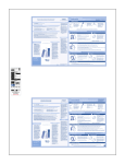
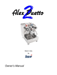
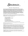
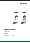
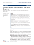
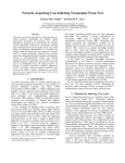
User Manual
Version 3
Revision 3
1
Table of Contents
Section
Contacting Slayer
Warranty Information
Important Safety Advisory
Water Treatment Requirements
Recommended Tools & Accessories
Installing Your Machine
Factory Settings
Using Slayer
Cleaning & Preventative Maintenance
Troubleshooting
Video Guides
Page
3
4
5
6
8
9
16
17
26
37
39
2
Contacting Slayer
Phone
+1 (206) 284-7171
Address
Seattle Espresso Machine Corporation
5628 Airport Way South Studio 238
Seattle, Washington 98108
United States of America
___
CEO & Creator
Jason Prefontaine
[email protected]
COO
Fred Baruch
[email protected]
Technical Support
[email protected]
Parts & Inventory
Melinda Davis
[email protected]
Sales
Brandon King
[email protected]
Customer Service & Office Admin
Elyse Stever
[email protected]
Engineering
Spencer Branting
[email protected]
Marketing & Content
Chris Elliott
[email protected]
3
Warranty Information
Slayer offers a 15-month limited warranty on all electrical and mechanical parts.
Wearable parts (including but not limited to rubber seals, gaskets, and o-rings) are
not covered under warranty, nor are labor or shipping charges.
Due to the nature and characteristics of wood(s) used on Slayer machines,
cracking, shrinking, and/or warping of this wood is not covered under warranty.
Damage to or failure of your Slayer machine due to inadequately treated water is
not covered under warranty. Read “Water Treatment Requirements” on page 6 for
information about water-related issues.
4
Important Safety Advisory
This guide includes important instructions about safe espresso machine installation,
operation, and maintenance. Read this manual completely before installing and
operating your Slayer espresso machine. Incorrect installation and operation may
result in damage to the equipment, personal injury, or even death. Disregarding the
instructions contained herein indemnifies Slayer from all resulting damages and
may void the machine’s warranty.
Shipping is coordinated by the customer and performed by a third party. Slayer is
not responsible for damage incurred during transport. Upon receiving your machine,
carefully inspect all packaging, equipment, and accessories for visible damage.
Photograph any visible damage and immediately contact your shipping company
representative. Comply with shipping company regulations. Do not connect your
machine to power, water, or drainage until all issues have been resolved or your
Slayer representative or reseller instructs you to do so. Failure to resolve issues
before using equipment may result in further damage or injury.
Installation should be performed by qualified personnel only and must comply with
all regulations and requirements of the authorities in your area. If guidance is
needed to safely install your machine, contact your Slayer representative or
reseller.
It is critical that an appropriately-rated and grounded electrical plug is used to
supply your machine with power. This is essential for the safe operation and use of
the equipment. Contact your Slayer representative or reseller with questions about
this requirement. If you are unsure about the safety of the electrical configuration,
do not attempt to install your machine.
Your Slayer espresso machine should only be used for the functions it was designed
to perform. Using your machine outside of its defined functionality – as it is
described in the "Using Slayer" section on page 23 of this guide – may be a safety
hazard, resulting in property damage, physical injury, or even death, and will
immediately void the warranty.
Slayer espresso machines are electrical appliances that should be used in a safe
manner appropriate to devices of their kind:
•
•
•
•
Do not connect your Slayer espresso machine to electrical power through an
extension cord. The machine must be directly connected to an appropriatelyrated and grounded power source.
Do not position the power cord in walkways or other areas with high foot
traffic.
Slayer espresso machines are designed to be used indoors. When using your
machine outdoors, take precautionary measures to protect it from moisture,
humidity, and other natural elements.
Before performing service on your machine, disconnect power source.
5
Water Treatment Requirements
Improper water treatment is the most frequent cause of espresso machine damage.
Water is complex and varies significantly between regions, so take great care to
test the water quality at your location and adjust as necessary. Employ the help of a
reliable company (Slayer recommends OptiPure and BWT) to evaluate your water
and recommend and administer treatments.
When evaluating water quality, the two most important factors to consider are
calcium carbonate and chloride:
Calcium Carbonate: dissolved mineral that determines the "hardness" or
"softness" of water.
The desirable range of hardness is 4-6 grains. Over time, calcium carbonate
accumulates as a hard substance, called “scale”, and will inhibit the flow of
water. Machines subjected to “harder” water (greater than 6 grains) will
accumulate scale faster and require maintenance sooner.
Chloride: chlorine combined with an electron from a negatively charged ion.
There are many types of chlorides, including calcium chloride, magnesium
chloride, sodium chloride, etc. Chlorides produce salts that impart a strong
taste, which alters the flavor of the espresso. Chlorides also encourage pitting
corrosion, which causes damage to the machine.
Your water filtration company will create a treatment plan based on your water
needs. Choose a filtration company that has solutions for addressing issues related
to both calcium carbonate and chloride.
Common treatment options include carbon filtration, ion exchange and reverse
osmosis:
Carbon Filtration: process by which water passes through the granular activated
carbon, which attracts and retains many chemicals in the water that have an
unpleasant taste or odor.
Carbon filtration is necessary for all Slayers. For water with 4-6 grains of
hardness, carbon filtration is likely the only necessary water treatment.
Ion Exchange: process by which water passes through an ion exchange system,
where where undesirable mineral components are retained and more desirable
substances such as sodium are released.
An ion exchange system should be used in combination with a carbon
filtration system and is especially beneficial for water in the range of 6-9
grains of hardness. This system is relatively inexpensive and effective in
6
removing inorganic substances. It does not, however, remove organic
substances, such as bacteria.
Reverse Osmosis with Blend-Back Valve (or Remineralized RO): process by
which water is forced through a semi-permeable membrane with selective pore
sizes at high pressure, then blended with the appropriate amount of desired
minerals.
Reverse osmosis may be a good solution for water in the range of 6-9 grains
of hardness, but is mandatory for water above 9 grains. When blending
minerals with the filtered water, target a TDS (total dissolved solids) value of
of 75-125 ppm. Experiment with various TDS levels to determine what is
ideal.
IMPORTANT: All Slayer espresso machines need to be connected to a carbon water
filter to remove chlorine, sediments, odor, and undesirable tastes from the water.
This requirement is in addition to any other necessary water filtration systems.
Filtration requirements may vary seasonally. Water should be tested during each
season to determine the best filtration plan. Once a filtration method has been
selected, take note of the filter’s peak capabilities. Contact the equipment vendor to
inquire about the life expectancy of the filters, then schedule replacement and reinstallation accordingly.
Every time a new water filter is installed, thoroughly rinse the filter before attaching
it to your machine or pump. Run water from the supply line through the filter and
down a drain for at least 2 minutes. Skipping this step will damage your machine.
Damage to or failure of your machine due to inadequately treated water is not
covered under warranty.
7
Recommended Tools & Accessories
To properly use and maintain your espresso machine, Slayer recommends owning
an assortment of tools and accessories. These can each be organized in two
categories: Beverage Preparation and Equipment Care & Maintenance. Specific
requirements accompany each recommendation.
Beverage Preparation
•
•
•
•
•
•
•
Espresso grinder
‣ Adjustable grind setting
‣ Capability for grinding very fine: espresso-to-Turkish
Gram scale
‣ Low resolution: 0.1-gram (1/10-gram) increments
Shot glass
Soft towel
Steaming pitcher
‣ Narrow spout
Tamper
‣ 58mm base diameter
Thermometer
Equipment Care & Maintenance
Tools
•
•
•
•
•
•
•
•
•
•
Allen key
Crescent wrench
Flat-head screwdriver
Grouphead brush
Needle-nose pliers
Phillips-head screwdriver
Pick or awl
Pliers
Socket wrench (9/16”)
Wrench
Supplies
• Approved espresso machine cleaner
• Approved espresso machine steam wand cleaner
• Non-abrasive surface cleaner
• Slayer lubricant
• Teflon tape
• Tung oil
Parts
See list of recommended spare parts on page
8
Installing Your Machine
Only qualified service personnel should install Slayer espresso machines. Incorrect
installation may result in injury and/or damage to the equipment. Please read the
"Important Safety Information" section on page 5 before beginning installation.
Install your Slayer espresso machine with the following ordered steps:
1.
2.
3.
4A-C.
5.
6.
7.
8.
Prepare Site
Unpack Equipment
Connect Drain Hose
Connect Water Line
Connect Pump
Connect Machine to Power
Fill Tanks
Turn On Heating Elements
Step 1: Prepare Site
Your installation site will need direct access to power, water, and drainage. Building
regulations vary by region, so confirm local requirements prior to connecting your
machine.
Using quality, treated water is essential to achieving the best possible results when
preparing coffee and may also extend the life of your machine. Read the Water
Treatment Advisory on pages 6-7 for information about avoiding and addressing
water-related issues.
Your Slayer espresso machine weighs approximately 160 kg (350 lb.) when filled
with water and needs to be installed on a structure that is capable of supporting its
weight.
Use the following diagram to locate and drill holes in the counter for the water and
drain lines. Note that electrical plugs vary in size and a larger hole may be required
to accommodate the main power cord.
9
2 Group
3 Group
10
Step 2: Unpack Equipment
Your Slayer espresso machine will arrive in a lidded wooden crate, bolted to a pallet
at the base. Unpack with the following steps.
Parts
•
•
•
•
•
and tools:
Phillips-head screwdriver
Two (2) Rubber feet (included)
Steam handles (included)
Drip tray mirror (included)
Three (3) nuts for drip tray mirror (included)
Procedure:
1. Use a phillips-head screwdriver to loosen and remove the screws
(approximately eight [8] screws) located along the lower edge of the crate.
2. Carefully lift the lid from the pallet.
3. Remove all banding and packing material from the machine.
4. Use a phillips-head screwdriver to loosen and remove the screws
(approximately two [2] screws) from the base of the pump, then detach it
from the pallet.
5. The machine is attached to the pallet with two (2) bolts that are screwed into
two (2) of its four (4) legs, one on each side of the machine. Use a socket
wrench to loosen and remove the two (2) bolts from the underside of the
pallet.
6. Attach the included rubber
feet to the bottom of the two
(2) legs that were bolted to
the pallet.
7. Prepare surface by laying out
one or more towels, which
will rest under the machine’s
feet and allow for easy sliding
into desired position.
8. Holding the machine by the
lower part of the Xs, as
shown, employ two (2) or
more people to lift the
machine up and onto the
towels on the prepared
Lift Here
surface.
9. Slide machine into desired
position, then left legs, one or two at a time, to remove towel(s).
10.Attach the steam handles by threading into place.
11.Attach the drip tray mirror using the three (3) included nuts.
12. Pull both steam actuators forward, into the “on” positions. Leave steam
actuators in the “on” positions until “Step 8: Turn on Heating Elements”.
11
Step 3: Connect Drain Hose
Parts
•
•
•
and tools:
Drain hose (included)
Hose clamp (included)
Flat-head screwdriver
Procedure:
1. Use the hose clamp to fasten
the drain hose to the drain
outlet, as shown.
‣ The drain hose has an inside
diameter of 5/8" (1.6cm).
2. Prevent clogging by ensuring
that the drain line always goes
downwards.
‣ Leave steam actuators in the “on” positions for “Step 8: Turn on Heating
Elements”.
Step 4A: Connect Water Line
For machines without hot water
IMPORTANT: Before connecting a water treatment system to your espresso
machine, rinse the system by running water through it for at least two (2) minutes.
Failure to follow this step will result in equipment damage. Read the Water
Treatment Requirements on pages 6-7 for information about avoiding and
addressing water-related issues.
Parts
•
•
•
and tools:
40”x3/8” braided stainless steel hose
60”x3/8” braided stainless steel hose (with 90-degree fitting)
Wrench
Procedure:
1. Use the shorter, 40”x3/8” braided hose to connect the water treatment
system outlet to the pump inlet.
2. Use the longer, 60”x3/8” hose to
connect the pump outlet to the
Inlet from
espresso machine water inlet
(located at the bottom-rear of
the machine).
Outlet to
‣ The end with the 90degree fitting should
connect to the espresso
machine.
‣ Leave steam actuators in the
“on” positions for “Step 8: Turn
on Heating Elements”.
12
Step 4B: Connect Water Line
For machines with hot water
IMPORTANT: Before connecting a water treatment system to your espresso
machine, rinse the system by running water through it for at least two (2) minutes.
Failure to follow this step will result in equipment damage. Read the Water
Treatment Requirements on pages 6-7 for information about avoiding and
addressing water-related issues.
Parts
•
•
•
and tools:
40”x3/8” braided stainless steel hose
Two (2) 60”x3/8” braided stainless steel hoses (with 90-degree fittings)
Wrench
Procedure:
1. Use the shorter, 40”x3/8” braided hose to connect the water treatment
system outlet to the pump inlet.
2. Use one of the longer, 60”x3/8” hoses to connect the pump outlet to the
espresso machine water inlet (located at the bottom-rear of the machine).
‣ The end with the 90-degree fitting should connect to the espresso
machine.
3. Use another of the longer, 60”x3/8” braided hoses to connect the T-fitting on
the pump to the hot water mix-valve inlet on the espresso machine (located
near the drip tray).
‣ The end with the 90-degree fitting should connect to the espresso
machine.
‣ Leave steam actuators in the “on”
Inlet from
positions for “Step 8: Turn on Heating
Elements”.
Outlet to
Outlet to
Hot Water
13
Step 4C: Adjust Hot Water Temperature
For machines with hot water
Parts and tools:
• Flat-head screwdriver
Procedure:
1. Remove the cup tray.
2. Use a large, flathead screwdriver to remove the two top and one lower rear
screws from the x-leg, then lift to remove the left rear side panel.
3. Use the adjustment needle-valve to regulate the amount of cold water that
mixes with the hot water.
‣ Turn counter-clockwise to increase the amount of cold water and decrease
the water temperature.
‣ Turn clockwise to decrease the amount of cold water and increase the
water temperature.
‣ Leave steam actuators in the “on” positions for “Step 8: Turn on Heating
Elements”.
Mix-Valve
Step 5: Connect Pump
Two (2) electrical cords extend from
outside of your Slayer espresso
machine. The thinner of these cords
has a small, white quick-connect plug.
Insert the quick connect plug into the
matching plug unit on the pump
motor.
Step 6: Connect Machine to Power
Inlet for Hot
IMPORTANT: Before beginning any electrical work on your machine, ensure that
both the red power switch and white heating element switch are in the "off"
position.
Your espresso machine will ship with the power configuration requested at the time
of purchase. Only an electrician or approved technician should wire the power cord
into an appropriately-rated plug end. Once the plug end is attached, insert the main
power cord into an appropriately-rated and grounded receptacle.
Step 7: Fill Tanks
Procedure:
1. Pull one steam actuator forward, into the “on” position, until it stops.
2. Turn on the main water line and red power switch; tanks will begin to fill.
‣ Wait to turn on the white heating element switch.
14
Filling will take approximately and is complete when the pump motor
ceases to work and a “click” is heard.
3. When Slayer has filled completely, move the brew actuators left, into the
“on” positions.
4. When water begins to run from the groupheads, return the brew actuator to
the "off" position.
‣ Leave steam actuators in the “on” positions for “Step 8: Turn on Heating
Elements”.
‣
Step 8: Turn On Heating Elements
1. Per step 7, ensure that both steam actuators are pulled forward, into the
“on” positions.
2. Move the white heating element switch to the "on" position by flipping it to
the left.
3. The machine is heated when steam begins to flow from the steam wand; at
this point, move the steam actuators into the “off” positions.
4. Lift to remove cup tray and check the inside of the machine for leaks or
collected water.
5. Allow Slayer to fully heat before use.
15
Factory Settings
Brew Tank Temperature:
Pre-Heat Tank Temperature:
Steam Tank Temperature:
Steam Pressure:
Flow Rate:
Pump Pressure:
93°C (200°F)
85°C (185°F)
118°C (245°F)
1.5 bar
40 grams per 30 seconds
9 bar
16
Using Slayer
Introductory Brewing Information
Slayer is a unique method for preparing espresso. Familiar processes and variables
may need to be altered when using this machine. Consider the following
generalizations and guidelines when preparing espresso with Slayer.
Roast Profile
Slayer utilizes flow restriction and multiple extraction sequences to permit
“flavor profiling” for individual coffees. Because dark-roasted beans may not
exhibit the full potential of your Slayer, nor the flavorful complexity of your
coffee, Slayer recommends light and medium roasts.
Ground Particle Size
Due to its slower introduction of water, permitted by a precision needle valve,
Slayer is able to brew espresso with coffee that has been ground at extremely
fine settings. Smaller particles reveal more of the coffee’s surface area to water,
thereby allowing the extraction of more flavor-carrying oils. These oils create a
rich, silky mouthfeel, mask bitterness, and increase perceived sweetness. When
setting up your grinder, target a setting that achieves the recommended
beverage yield with the recommended dose weight in the recommended brew
time. Continue reading for recommendations regarding these brewing
parameters.
Dose Weight & Basket Size
During its extended “pre-brew” phase, Slayer saturates the ground coffee puck
to an extent of thoroughness that no other espresso machine can match. As a
result, the coffee puck’s resistance to high pressure and maximum flow is
minimal. In order to achieve adequate extraction time, Slayer recommends
using 19-21 grams of ground coffee in the included portafilter basket. Lighter
doses and/or larger baskets will lead to prohibitively short extraction times and
may cause channeling.
Bed Depth & Tamp Pressure
With most espresso machines, firmly tamping ground coffee is essential to
forming a puck through which water will evenly flow. Due to its slower
introduction of water, Slayer changes the importance of tamping: instead of
tamping to a specific pressure (e.g. 30 lb.), Slayer recommends tamping to a
specific depth in order to achieve the adequate headspace between the coffee
puck and the shower screen. This space allows the coffee to release gas and
bloom before brewing. To ensure consistent results, target a tamp depth that
levels the top of the tamper piston with the top of the portafilter basket
(approximately 10 mm).
Brew Time
With most espresso machines, extraction should last 25-30 seconds. Due to its
slower introduction of water, Slayer may brew espresso in 40 seconds or more.
Begin by targeting a 45-second (20s pre-brew + 25s brew) extraction time.
17
Preparing Espresso
Slayer’s brew actuator allows for three positions: "off", “pre-brew", and "full brew".
The grouphead is in the "off" position when the brew actuator is moved all the way
right. The "pre-brew" setting is activated when the actuator is moved to the middle
of the group. "Full brew" is achieved when the actuator is moved all the way left.
Pre-brew position
Full-brew position
The following guidelines represent a good starting point when first using Slayer.
Coffee is a complex food item that differs from variety to variety, farm to farm, and
even seed to seed. Changes in brewing variables – including grind, dose,
temperature, flow rate, time, etc. – affect all coffees uniquely.
Standard Shot
The procedure for brewing a standard shot is similar to that for other espresso
machines:
1. Remove the portafilter from the grouphead and wipe the basket with a
clean, dry towel.
2. Set the grind to the same degree of coarseness as you would for another
espresso machine.
3. Grind and dose 19-21 grams of coffee into the portafilter.
4. Tamp coffee to approximately 30 pounds of pressure, briefly flush group,
then lock the portafilter into the grouphead.
5. Move the brew actuator directly to the "full brew" position.
6. Allow the espresso to brew until the preferred extraction has been
achieved (when blonding occurs, when the desired beverage yield has
dispensed, or when the desired brew time has elapsed), then move the
actuator to the "off" position.
7. Remove the portafilter from the grouphead and knock out spent coffee.
Wipe the portafilter with a clean towel to remove grounds and oil.
18
8. Briefly move the brew actuator to the "full brew" position to purge
grounds and oil from the dispersion screen. Move the grouphead to the
"off" position and return the portafilter.
"Slayer Shot"
To brew a "Slayer shot", ensure that the flow rate is at the desired setting and
the grinder is set finer than normal, then:
1. Remove the portafilter from the grouphead and wipe the basket with a
clean, dry towel.
2. Grind and dose 19-21 grams of coffee into the portafilter.
3. Tamp the ground coffee to a depth of approximately 10mm, briefly flush
group, then lock the portafilter into the grouphead.
4. Move the brew actuator into the center of the grouphead to activate prebrew.
5. Pre-brew times will vary based on the dose, grind, flow rate, brew
temperature, and characteristics of the coffee. The average Slayer prebrew takes approximately 20 seconds. Watch the bottom of the portafilter
basket shot mirror to see when the coffee puck becomes fully saturated.
6. The fully saturated portafilter basket will begin to drip. Immediately
before espresso starts to flow consistently, move the brew actuator to the
"full brew" position.
7. Allow the espresso to brew until the preferred extraction has been
achieved (when blonding occurs, when the desired beverage yield has
dispensed, or when the desired brew time has elapsed), then move the
actuator to the "off" position.
8. Remove the portafilter from the grouphead and knock out spent coffee.
Wipe the portafilter with a clean towel to remove grounds and oil.
9. Briefly move the brew actuator to the "full brew" position to purge
grounds and oil from the dispersion screen. Move the grouphead to the
"off" position and return the portafilter.
Extended Pre-Brew: Enhancing Sweetness
When espresso lacks sweetness, the pre-brew phase may be extended to extract
more of the naturally-sweet oils:
1. Follow "Slayer Shot" steps 1-5 above, but allow the espresso to continue
extracting in the “pre-brew” stage until it has dispensed up to 7 grams
(0.25 ounces).
2. Move the brew actuator to the "full brew" position, then resume "Slayer
Shot" steps 7-9.
19
Reduced Flow: Muting Acidity
Undesirable acidity can be softened by moving the actuator back to the middle
position at the end of the extraction process:
1. Follow "Slayer Shot" steps 1-6.
2. When the machines dispenses approximately two-thirds of the desired
volume, return the brew actuator to the middle position, then resume
"Slayer Shot" steps 7-9.
”Bumped” Pressure: Increasing Acidity
If more acidity is desired, the full-brew stage can be briefly engaged before prebrew:
1. Follow "Slayer Shot" steps 1-3.
2. Move the brew actuator to the "full brew" position until the grouphead
pressurizes (less than 1 second), then quickly return the actuator to the
"pre-brew" position.
‣ Engaging “full brew” for longer than 1 second may cause the puck to
choke, extending extraction and resulting in undesirable flavor.
3. Resume "Slayer Shot" steps 4-9, combining instructions for “Enhancing
Sweetness” and “Reducing Acidity”, if desired.
Steaming Milk
Slayer produces powerful steam by combining high pressure with restricted steam
tip holes. Various steam tip options (numbered 0-5) are available to allow the
barista to customize their steaming experience and milk texture.
Steam milk with the following steps.
1. Fill a cold pitcher with the desired volume of fresh milk.
2. Immediately before steaming milk, aim the steam wand toward the drip tray
or into a towel and pull the steam actuator forward to release steam and
purge condensation. Then, turn off the steam wand.
3. Submerge the steam tip in milk and turn on the steam wand.
4. Immediately move the pitcher down to expose the steam tip to the surface of
the milk, incorporating fine air bubbles.
5. When the milk reaches body temperature, submerge the steam tip again,
then tilt the pitcher to form a gentle whirlpool.
6. When the pitcher feels hot, turn off the steam wand.
‣ The final milk temperature should be 65-68ºC (150-155ºF).
7. Wipe the steam wand with a damp cloth, removing all milk residue, then
briefly turn on the steam wand to purge milk from the wand.
20
Dispensing Hot Water
Hot water tap included only upon request
The hot water spout is activated with a push button located above the spout. Push
the button once to dispense water; push again to turn off water.
Hot water is drawn from the steam tank and mixed with incoming cold water.
Frequent or heavy use of the hot water spout may result in reduced steam tank
pressure and temperature, causing decreased steaming ability.
Adjust Flow Rates
Flow rate is controlled by a precision needle valve, which is located inside of the
machine on top of the brew tank. Adjust the flow rate with the following steps.
Parts
•
•
•
and tools:
Empty 8-ounce vessel
Gram scale
Timer
Procedure:
1. Ensure that Slayer is fully heated.
2. Remove portafilters from all groupheads and set aside.
3. Begin with one grouphead: briefly move the brew actuator to the "pre-brew"
position, then to the "full brew" position for a few seconds before returning
the grouphead to the "off" position.
4. Beneath the same grouphead, place a container on a scale and tare the scale
to zero.
5. Simultaneously move the brew actuator to
the "pre-brew" position and start a timer.
Needle Valve Adjustment Knob
6. When the timer reaches 30 seconds,
remove the container and scale,
then move the brew actuator to
the "off" position.
7. Weigh the container again
without taring the scale to
determine how much water
dispersed in the allotted time.
8. Use this weight to determine
flow rate, which is expressed in
these terms: x grams of water
per 30 seconds.
‣ Slayer recommends starting
with a flow rate of 40-60
grams of water per 30
seconds. The actual flow
rate may be within a range of +/- 2 grams of the desired flow rate.
21
To decrease the flow rate, turn the blue control knob on the needle valve
clockwise.
‣ To increase the flow rate, turn the blue control knob on the needle valve
counter-clockwise.
9. Repeat all steps for each grouphead.
‣
IMPORTANT: Over-tightening the valve may break the needle inside. Only adjust
the flow rate incrementally to avoid damage.
Adjust Brew Tank Temperature
At the Slayer studio, brew tanks are set to 93ºC (200ºF). Each grouphead has its
own PID temperature controller, which can be manipulated independently. Adjust
the brew tanks’ temperatures with the following steps.
1. Begin with one grouphead:
briefly press the
corresponding PID controller’s
green "SEL" button, which will
engage the red "SV" light.
‣ The “C2”, “AL1”, and “AL2”
indicators are not used on
Slayer.
2. Use the up and down arrow
buttons to select the desired
temperature.
3. Press "SEL" again to return to
normal operation, indicated by
the red "SV" light turning off.
‣ The new temperature will be achieved and stable within 10 minutes.
4. Repeat all steps for each grouphead.
NOTE: Each of the brew tanks’ PIDs has an "F" printed on its plastic exterior,
which indicates temperature readings in degrees Fahrenheit. However, the actual
temperature may read in either Fahrenheit or Celsius, depending on your
request at the time of ordering.
Adjust Brew Pump Pressure
At the Slayer studio, the brew pump pressure is set at 9 bar. Actual brew pressure,
as indicated by the pressure gauge on the face of your machine, will be influenced
by incoming water pressure (line pressure) at your location. Adjust the brew pump
pressure with the following steps.
1. Lock a loaded portafilter, blind insert, or Scace device in the grouphead, then
move the brew actuator to the “full brew” position.
22
2. During "full brew", watch the
brew pressure gauge and turn
the pump screw to adjust the
pump pressure.
‣ Turn counter-clockwise to
decrease the pump
pressure.
‣ Turn clockwise to increase
the pump pressure.
3. Reconfigure flow rate per
instructions under “Using
Slayer > Adjust Flow Rates”.
NOTE: Due to the unique method
by which Slayer espresso
machines read brew pressure,
the pressure gauge will read 0
bar unless a loaded portafilter,
blind insert, or Scace device
provides back-pressure.
Adjust Steam Tank Temperature & Pressure
At the Slayer studio, steam tanks are set to 118°C (245°F). The temperature of the
tank is directly related to the steam pressure: increasing the temperature will
increase the pressure, while decreasing the temperature will decrease the pressure.
The factory-set temperature of the steam tank produces a pressure of 1.5 bar. If
the steam is more or less powerful than you prefer, adjust with the following steps.
1. Briefly press the Love Controller’s "SET" button and wait for the screen to
begin flashing.
2. Press the "SET" button again to access the steam tank set temperature. A
red LED will light under “out2”.
‣ Use the up and down arrow buttons to select the desired temperature,
making only incremental adjustments.
3. Press the "SET" button again to confirm new temperature setting and return
to original screen.
4. Pull a steam actuator forward
to engage steam, then wait
until the Love Controller’s
"Out 2" red light turns on.
5. Return the steam actuator to
the "off" position, then wait
until the "Out 2" light turns
off.
6. Check the steam pressure
gauge inside Slayer to
confirm new pressure setting.
23
NOTE: The steam and pre-heat tanks’ Love Controller has an "F" printed on its
plastic exterior, which indicates temperature readings in degrees Fahrenheit.
However, the actual temperature may read in either Fahrenheit or Celsius,
depending on your request at the time of ordering.
Adjust Pre-Brew Timers
Pre-brew timers included only upon request
The pre-brew timers allows the barista to minimize brew actuator movement while
still making use of the pre-brew function. Upon request, each group can be
outfitted with its own timer. To prepare espresso with the pre-brew timer, see
instructions under “Using Slayer > Using Pre-Brew Timer” on page 25.
The timer is activated with a push button located to the right of the corresponding
grouphead. When the button is in the "on" position, all extractions will be regulated
by the timer. The timer can be adjusted with a metal knob located beneath the drip
tray.
Adjust the pre-brew timer with the following steps.
1. Locate the pre-brew timer push button(s) on the right side of the
corresponding grouphead(s). When the button is in the "on" position, all
extractions will be regulated by the
timer.
2. With the pre-brew timer off, prepare a
shot of espresso with your
preferred method, using both
pre-brew and full brew
stages. Time the manual pre-brew
stage.
3. Remove the portafilter and use the
push button to activate the pre-brew
timer functionality.
Time adjustment knobs
4. Move the brew actuator left, to the "full brew"
position. Though the actuator will be in the
"full brew" position, the pre-brew stage will be performed for the stored time
before Slayer automatically engages the full-brew stage. Time the automated
pre-brew stage.
5. Locate the metal knob(s) underneath the drip tray. Turn as necessary, until
the automated pre-brew time in step 4 is equal to the desired pre-brew time
noted in step 2.
‣ Turn counter-clockwise to decrease the pre-brew time.
‣ Turn clockwise to increase the pre-brew time.
24
Using Pre-Brew Timers
The pre-brew timer allows the barista to minimize brew actuator movement while
still making use of the pre-brew function. It can be activated, deactivated, and
programmed with the corresponding buttons and knobs; see instructions under
“Using Slayer > Adjust Pre-Brew Timer” on page 24.
To prepare espresso with the pre-brew timer functionality,
1. Use the push button to activate the pre-brew timer functionality.
2. Grind, dose, and tamp coffee as usual, then lock the portafilter in the
grouphead.
3. Move the brew actuator to the "full brew" position to begin extraction. Slayer
will automatically initiate the pre-brew and full brew stages.
4. Allow the espresso to brew until the preferred extraction has been achieved
(when blonding occurs, when the desired beverage yield has dispensed, or
when the desired brew time has elapsed), then move the actuator to the
"off" position.
5. Remove the portafilter from the grouphead and knock out spent coffee. Wipe
the portafilter with a clean towel to remove grounds and oil.
6. Briefly move the brew actuator to the "full brew" position to purge grounds
and oil from the dispersion screen. Move the grouphead to the "off" position
and return the portafilter.
Pre-Heat Tank Temperature
At the Slayer studio, brew tanks are set for optimal performance at to 85°C
(185°F). We do not recommend changing the preheat temperature. Changes to the
pre-heat temperature may negatively affect the machine’s performance and pose a
safety risk. Please contact your Slayer representative, reseller, or technician before
changing this setting.
NOTE: The steam and pre-heat tanks’ Love Controller has an "F" printed on its
plastic exterior, which indicates temperature readings in degrees Fahrenheit.
However, the actual temperature may read in either Fahrenheit or Celsius,
depending on your request at the time of ordering.
25
Cleaning & Preventative Maintenance
Keeping your machine clean and properly maintained is essential to ensuring
espresso quality and equipment longevity. Espresso machines require both daily
cleaning and ongoing periodic maintenance. The frequency with which these tasks
should be completed will depend on the location and use of your espresso machine.
The follow recommendations assume heavy use in a commercial setting.
Please observe the following preventative maintenance schedule.
CAUTION: Slayer and its parts may be very hot. Please read the Important Safety
Information section prior to using Slayer and take the necessary steps to protect
yourself and others.
Daily
• Body
• Groupheads
• Steam Wands
Every 1-2 Months
• Portafilter Gaskets
• Dispersion Screens
Every 6 Months
• Steam Tank
• Steam Valve Pin O-Rings
• Shoulder Bolt Shims
• Brew Actuator
Every 12-18 Months
• Expansion Valve
• Anti-Suction Valve
• Steam Valve
• Water Level Probe
• Brew Actuator Bearing
Wood Care
26
Daily
Body
Parts and tools:
• Soft, clean towel
• Non-abrasive cleaner, e.g. window cleaner (optional)
Procedure:
Use a soft, clean towel to wipe the surfaces of the machine. Do not use
abrasive cleaners. Small amounts of window cleaner may be used on the
stainless steel components. If your Slayer has wood panels, please refer
to the “Wood Care” section.
Groupheads
Cleaning and backflushing the groupheads prevents the build up of coffee
oils. Backflush each group at least twice daily: once with water and once with
an approved espresso machine cleaning powder.
To maximize efficiency and lengthen the life of wearable parts, we
recommend keeping two (2) sets of dispersion screens and screws on hand.
Alternate between sets for each end-of-day backflush (see below).
General Group Cleaning
Recommended as part of every backflush cycle, or as needed
Parts
•
•
•
and tools:
Cleaning brush or towel
Flat-head screwdriver
Portafilter with basket removed
Procedure:
1. Begin with one grouphead: use a cleaning brush or towel to scrub the
portafilter gasket and loosen oil and coffee grounds.
2. Remove the dispersion screw and screen with a flat-head screwdriver
and rinse with clean water.
‣ Ensure that the dispersion screw holes remain clear of coffee
grounds, as they may otherwise damage internal parts of the
grouphead.
3. Use a clean, damp towel to wipe oil and grounds from the face and
sides of the dispersion block, as well as the portafilter body.
4. Return the clean dispersion screw and screen to the grouphead.
5. Thoroughly rinse portafilter with hot water, insert basket, and lock in
grouphead.
‣ CAUTION: failure to reinstall the dispersion screw and screen
before next use may cause the grouphead to clog with coffee
particles. Do not attempt to brew espresso before the dispersion
screw and screen have been correctly installed.
27
6. Repeat all steps for each grouphead.
Backflushing with Water Only
Recommended once daily
Parts
•
•
•
•
and tools:
Cleaning brush or towel
Flat-head screwdriver
Blind portafilter insert
Portafilter
Procedure:
1. Complete “General Group Cleaning” steps 1-4 above.
2. Begin with one grouphead: replace portafilter basket with blind insert
and lock in grouphead.
3. Move the brew actuator to the "full brew" position and activate the
brew cycle for 10 seconds, then move the actuator back to the “off”
position and wait 10 seconds. Repeat 5 times.
4. Repeat steps 1-3 for each grouphead.
5. Remove blind insert from portafilter and use a clean, damp towel to
wipe oil and grounds from portafilter body.
6. Thoroughly rinse portafilter with hot water, insert basket, and lock in
grouphead.
Backflushing with Espresso Machine Cleaner
Recommended once daily for commercial settings; once weekly for homes
Parts
•
•
•
•
•
•
•
and tools:
Replacement shower screens (part #46000-50070)
Replacement dispersion screws (part #46000-50080)
Cleaning brush or towel
Flat-head screwdriver
Approved espresso machine cleaner
Blind portafilter insert
Portafilter
Procedure:
1. Complete “General Group Cleaning” steps 1-3 above for all
groupheads.
2. Soak dispersion screws and screens overnight in a solution of hot
water and approved espresso machine cleaning powder. Later, rinse
thoroughly with clean water.
3. Install clean, second sets of dispersion screws and screens.
4. Remove the baskets and portafilter springs from the portafilters and
soak overnight with the dispersion screws and screens. Later, rinse
thoroughly with clean water.
‣ Do not soak portafilters with wood handles. Exposure to water and/
or chemicals may cause wood to crack or warp.
28
5. Begin with one group: place the included blind insert in a portafilter,
add approved espresso machine powder, and lock in grouphead.
6. Move the brew actuator to the "full brew" position and activate the
brew cycle for 10 seconds, then move the actuator back to the “off”
position and wait 10 seconds. Repeat 5 times.
7. Remove and rinse the portafilter.
8. Repeat steps 6-7 with water only, backflushing 5 times.
9. Repeat steps 5-8 for each group.
10.Remove blind insert from portafilter and use a clean, damp towel to
wipe oil and grounds from portafilter body.
11.Thoroughly rinse portafilter with clean, hot water.
12.Later, after soaking, reattach portafilter spring and basket and lock
portafilter in grouphead.
Steam Wands
After steaming milk, clean the exterior of the steam wand by wiping it
thoroughly with a damp towel, then clear its interior by briefly allowing steam
to flow.
If the steam wand tips clog, soak in hot water for several minutes, then
briefly engage steam with wand submerged. For tough clogs, use an
approved espresso machine steam wand cleaner.
Every 1-2 Months
Replacing Shower Screen
➡ vimeo.com/20084652 (password: prebrewpressure)
The dispersion screen may become bent or damaged and should be replaced
periodically. Ideally, the mesh screen will sit firmly against the metal backing. If
a gap forms, replace the dispersion screen.
Parts and tools:
• Replacement shower screen (part #46000-50070)
• Flat-head screwdriver
Procedure:
1. Complete steps 1-3 of “General Group Cleaning” under “Grouphead”.
2. Discard old dispersion screen.
3. Install new screen and secure with the screw from step 1, taking care
not to over-tighten. Tighten the screw with your fingers until it is
secure, then rotate an additional 90 degrees (1/4 turn) with the
screwdriver.
‣ CAUTION: failure to reinstall the dispersion screw and screen
before next use may cause the grouphead to clog with coffee
particles. Do not attempt to brew espresso before the dispersion
screw and screen have been correctly installed.
29
‣
For additional assistance with this procedure, refer to parts
diagrams on pages 58-74.
Replacing Portafilter Gasket
➡ vimeo.com/20084652 (password: prebrewpressure)
The portafilter gasket forms a seal between the portafilter and the grouphead,
preventing leaks. Over time, the portafilter gasket will become hard and lose its
seal. If it becomes difficult to insert the portafilter or if dripping occurs around
the portafilter body while brewing, replace the portafilter gasket.
Parts and tools:
• Replacement 6mm portafilter gasket (part #46000-56091)
• Flat-head screwdriver
• Pick or awl
• Cleaning brush or towel
Procedure:
1. Complete steps 1-3 of “General Group Cleaning” under “Grouphead”.
2. Use a pick or awl to remove the old portafilter gasket, pressing the
pick into the gasket and pulling downwards. If the gasket breaks into
small pieces, continue picking until the entire gasket has been
removed.
3. Insert new portafilter gasket in such a way that the flat side touches
the grouphead and the round side is visible from the bottom. Gently
press the gasket into place, then use a screwdriver, pick, or awl to
secure it in place.
4. Return the clean dispersion screw and screen to the grouphead.
‣ CAUTION: failure to reinstall the dispersion screw and screen
before next use may cause the grouphead to clog with coffee
particles. Do not attempt to brew espresso before the dispersion
screw and screen have been correctly installed.
‣ For additional assistance with this procedure, refer to parts
diagrams on pages 58-74.
Every 6 Months
Before Maintenance Procedure
Before starting the 6-month maintenance procedure, make the following
preparations.
1. Turn off your machine by moving both the red and white switches to
the "off" position.
2. Turn off water supply, either at the source or at the filtration system.
3. Disconnect machine from power source.
4. Lift to remove cup tray assembly.
30
Draining Steam Tank
➡ vimeo.com/20110440 (password: prebrewpressure)
As steam is produced and exits the wand, minerals in the water are left
behind build up inside the boiler. The steam tank needs to be drained
periodically to remove these excess minerals. For assistance with this
procedure, refer to parts diagrams on pages 58-74.
Parts and tools:
• 1/4” teflon or poly tubing
• Wrench
Procedure:
1. Follow instructions in above video to remove the machine’s left side
panel.
2. Locate the shutoff valve on the lower left side of the steam boiler.
Insert a 1/4" teflon tube into the quick-connect fitting located after
the shut-off valve, pressing firmly until the tube clicks into place.
‣ If teflon tubing is not available, poly tubing may be used
instead. If using poly tubing, see note under step 7 before
beginning step 7.
3. Aim the open end of the 1/4" teflon tube into a sink or bucket, then
secure the tube or weigh it down with a heavy object.
4. Use a wrench to open the shut-off valve. The steam in the boiler will
push all of the water in the tank through the teflon line and into the
drain.
‣ If using poly tubing, do not open the valve fully; high pressure will
damage tubing.
5. Allow the tank to drain, then continue with steps 6-. Other
maintenance tasks may be performed during this time.
6. Close the shut-off valve and carefully remove the tube from the quickconnect fitting.
7. Reinstall the side panel.
8. Reconnect power and turn on water supply.
9. Move brew and steam actuators to the “on” positions.
10.Engage red power switch to refill tanks.
11.When water begins to flow from groupheads, indicating that the tanks
have filled, move brew actuators to the “off" positions. Keep steam
actuators in the “on” position.
12.Engage white power switch to turn on heating elements.
13.When steam begins to exit wands, close steam actuators and allow
machine to fully heat.
Steam Valve Pin O-Rings
➡ vimeo.com/20114980 (password: prebrewpressure)
When the steam actuator is moved into the “on” position, it pushes a brass
pin into the steam valve, which causes the valve to open and allows steam to
31
flow. The two (2) o-rings on the steam valve pin should be replaced every six
(6) months.
[INSERT STEAM VALVE DIAGRAM]
Parts and tools:
• #8 - Part # 5309, Steam Valve Pin O-Rings
• Flat-head screwdriver
• 3/4” socket wrench
• Pliers
• Pick or awl
Procedure:
1. Remove top/side first?
2. While holding the corresponding nut on the machine’s interior with a 3/4”
socket wrench, use a flat-head screwdriver to loosen and remove the
shoulder bolt.
3. Use pliers to remove the steam valve pin (#7).
4. Use a pick or awl to remove the o-rings (#8) from the steam valve pin
and discard them. Put the new o-rings on the pin.
5. Rub Slayer lubricant on the pin and return the pin to the steam valve.
Shoulder Bolt Shims
The shoulder bolt’s shims create a snug fit between the steam actuator hub
and the side panel. Any time the steam actuator is removed, the shims
should be replaced.
[INSERT STEAM SHOULDER DIAGRAM]
Parts and tools:
• #12 - Part # 5315, Shoulder Bolt Shim
• Screwdriver
Procedure:
1. Remove the shims from the shoulder bolt and discard them. Place two (2)
new shims on the shoulder bolt.
2. Rub Slayer lubricant inside the steam actuator hub.
3. Attach the steam actuator hub and shoulder bolt to the machine,
tightening with screwdriver. Confirm fit by wiggling the hub. If the hub
does not fit snugly, remove the shoulder bolt and add more shims.
4. Test again and repeat step 3 until hub and panel fit snugly.
Brew Actuator
➡ VIDEO (password: prebrewpressure)
If the brew actuator becomes loose, tighten with the following steps.
Parts and tools:
32
•
•
Flat-head screwdriver
Allen key
Procedure:
1. Use a flat-head screwdriver to remove the lock screw from the top of the
brew actuator.
2. Tighten the locking nut with an allen key. Test tightness by moving the
actuator back and forth.
3. Adjust locking nut until desired tension is achieved.
4. Replace lock screw.
Every 12-18 Months
Begin the 12-18 month preventative maintenance procedure by turning off
the machine’s white and red power switches, unplugging its power source,
disconnecting the main water line, and draining the steam.
After completing the following preventative maintenance tasks, reconnect the
machine to power and water, then turn on the red power switch only. Once
the machine has completely filled with water, turn on the white heating
element switch. Use machine only after it has heated fully.
Expansion Valve
➡ vimeo.com/20211342 (password: prebrewpressure)
After 12-18 months, the seal in the expansion valve will wear out, causing
water to leak from the valve. This will lead to temperature loss in the preheat tank and premature failure of the water filtration system. To diagnose a
worn expansion valve, look for leaking water in the expansion valve drain
tube and listen for beeping from the Love Controller, which indicates a cold
pre-heat tank.
[INSERT DIAGRAM]
Parts and tools:
• #3 - Part # 5011, Expansion Valve
• #20 - Part # 5015, Copper Gasket
• Wrench
• Teflon tape
Procedure:
1. Partially drain pre-heat tank.
2. Disconnect silicone tube from the expansion valve.
3. Use a wrench to remove the expansion valve from the pre-heat tank and
discard.
4. Apply teflon tape to the threads of the new expansion valve and slide a
new copper gasket in place.
5. Install a new expansion valve, tightening with a wrench.
33
6. Reconnect the silicone tube.
Anti-Suction Valve
➡ [VIDEO] (password: prebrewpressure)
The anti-suction valve prevents a vacuum from forming in the steam tank,
which would suck milk into the steam tank.
[INSERT DIAGRAM]
Parts and tools:
• #5 - Part # 5014, Anti-Vacuum Valve
• #8 - Part # 5015, Copper Gasket
• Teflon tape
1. Drain the steam tank by engaging both steam actuators until steam
ceases to flow from the wands.
2. Remove the anti-suction valve and discard it.
3. Apply teflon tape to the threads of a new anti-vacuum valve and slide a
new copper gasket into place.
4. Install the new valve, tightening with a wrench.
Steam Valve Seals
➡ vimeo.com/20335705 (password: prebrewpressure)
If steam leaks from either the tip or rotating base of the steam wand, replace
the steam valve’s rubber seals, o-rings and teflon bushing.
[INSERT DIAGRAM]
Parts and tools:
• #2 - # 5310, Steam Seat Gasket
• #5 - # 5306, Teflon Bushing
• #6 - # 5305, Teflon Busing O-Ring
• #8 - # 5302, Valve Nut O-Ring
• Two (2) large wrenches
• Pick or awl
• Slayer lubricant
• Needle-nose pliers
• Teflon tape
Procedure:
1. Drain the steam tank by engaging both steam actuators until steam
ceases to flow from the wands, then return both steam actuators to the
“off” position.
2. Remove the tube that connects the steam tank to the steam valve.
3. Loosen and remove the steam wand tip.
34
4. Use a wrench to loosen the steam wand valve nut, then remove the nut
and the steam wand. Watch for the teflon bushing that sits inside the ball
joint, ensuring that it doesn’t fall out.
5. Use a pick or awl to remove the o-ring (#8) from the inside of the steam
wand valve nut.
6. Clean the inside of the nut and insert a new o-ring. Apply Slayer lubricant
to the o-ring and inside of the nut.
7. If the teflon bushing (#5) appears dark or flattened, discard it and install
a new o-ring. Apply Slayer lubricant to the new o-ring and insert it in the
steam wand valve nut.
8. Reattach steam wand.
9. Remove steam actuator hub.
10.Use wrench to secure steam valve body; use second wrench to remove
the steam valve’s large, brass nut.
11.Remove spring from steam valve body and use needle nose pliers to
remove the steam seat from the valve body.
12.Use a pick or awl to separate steam seat gasket (#2) from steam seat.
Insert new steam seat gasket in seat.
13.Reinsert steam seat and spring in the steam valve.
14.Apply teflon tape to the threads of the brass nut.
15.Use wrench to secure steam valve body; use second wrench to tighten
brass nut.
16.Reconnect the steam tubes to the valve and steam tank.
17.Replace the steam actuator hub.
Water Level Probe
➡ VIDEO (password: prebrewpressure)
Parts and tools:
• Wrench
• Teflon tape
• Replacement probe
Procedure:
1. Drain steam tank.
2. Remove wire from probe and set aside.
3. Use a wrench to secure the larger of the two nuts at the base of the
probe, then hold the nut in place and remove probe assembly.
4. Apply teflon tape to the threads of the nuts and add copper gasket.
5. Screw a new probe onto the tank.
6. Reconnect wire to probe.
Brew Actuator Bearing
➡ VIDEO (password: prebrewpressure)
Replace parts within bearing. (1-3 years)
around 1 million cycles (ever 2-3 years) some parts need to be
replaced - ask Jason
35
Wood Care
Keep all wood components dry and away from harsh elements. Use a soft, dry
towel to wipe the wood clean. For tougher messes, use a slightly damp towel,
then promptly dry the wood. Do not use chemicals or cleaning agents.
Moisture and chemicals may cause the wood to warp or crack.
If the wood begins to look aged and dry, rub a small amount of tung oil into
the wood with a clean, soft towel. Allow the oil to sink into the wood for at
least five minutes, then wipe the remaining oil off with a dry towel.
36
Troubleshooting
Use this list of common symptoms to diagnose and resolve issues you experience
with your espresso machine. Slayer’s instructional videos are password-protected,
but can be accessed with the code “prebrewpressure”.
Symptom
Possible cause(s)
Instructional video
Bent gauges
Needle valve closed
vimeo.com/20345156
Brew tank cold; pre-heat
and steam tanks normal
Tripped thermostat or
faulty probes and/or PIDs
vimeo.com/20211342
Brew and pre-heat tanks
cold; steam tank normal
Faulty expansion valve
vimeo.com/20211342
All tanks cold
Tripped breaker and/or
white power switch off
vimeo.com/20219480
High pressure during prebrew
Coffee ground too fine
vimeo.com/20293720
Hissing from machine’s
rear-left
Leaking pressure release
valve
vimeo.com/20309382
Steam pressure low; brew Faulty check valve
pressure normal
vimeo.com/20208524
Steam pressure low and/
or slow refill
Dirty probe
vimeo.com/20303179
Fast flow during pre-brew
Faulty switch and/or bad
connection to Molex
connector and/or missing
magnet
vimeo.com/20296673
Pump runs continuously
Loose switch and/or brew
actuator not in “off”
position
vimeo.com/20300413
Steam tank overfills
Faulty solenoid valve and/
or dirty probe and/or bad
connection to probe
vimeo.com/20306832
Dripping group screens
Worn o-rings at valve
insert and/or lower valve
stem
vimeo.com/19575557
Dripping steam wand
Worn steam cup seal and/ vimeo.com/20335705
or o-rings
Leaking group cap and/or
bayonet
Worn o-rings at upper
valve stem
vimeo.com/20218411
37
Symptom
Possible cause(s)
Instructional video
Leaking steam actuator
hub
Worn steam valve pin orings
vimeo.com/20114980
No flow during pre-brew
Needle valve closed
vimeo.com/20220777
38
Video Guides
Use these videos to learn common procedures for your espresso machine. Slayer’s
instructional videos are password-protected, but can be accessed with the code
“prebrewpressure”.
Procedure
Instructional video
Adjusting pre-brew flow rate
vimeo.com/20121811
Replacing grouphead seals and/or
screens
vimeo.com/20084652
Replacing steam valve pin
vimeo.com/20114980
Adjusting steam actuator tension
vimeo.com/20114980
Adjusting brew actuator tension
vimeo.com/20216962
Removing body panels
vimeo.com/20110440
Adjusting expansion valve
Adjusting brew temperature
vimeo.com/20120809
Adjusting pre-heat and steam
temperature
vimeo.com/20205234
Auto-tuning PID
vimeo.com/21042015
39