1
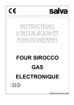
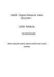
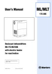
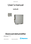
User’s manual
Desiccant Dehumidifier
MA-C Series
Effective from serial no. 1000
190TGB-1022
© Munters Europe AB 2002
MA-C
MA-Series Dehumidifiers
CONTENTS
1. SUPPLIER INFORMATION
1.1
1.2
1.3
1.4
1.5
7 FAULT ISOLATION
Introduction .................................................... 4
Warranty ........................................................ 4
Safety ............................................................ 4
Misuse of Equipment .................................... 4
Safety Symbols ............................................. 4
7.1
8 TECHNICAL DATA ............................................. 18
8.1
8.2
8.3
8.4
2 PRINCIPLE OF OPERATION
2.1
2.2
2.3
Product Description ....................................... 5
General .......................................................... 5
Desiccant Rotor ............................................. 5
Dimensions and Weight ........................... 19
Capacity Diagram ..................................... 20
Fan Diagrams ........................................... 21
Sound Data ............................................... 22
9 GENERAL ASSEMBLY ...................................... 24
3 PRODUCT DESCRIPTION
3.1
3.2
3.3
3.4
Fault isolation procedures ........................ 17
9.1
9.2
9.3
Construction .................................................. 6
Standard Equipment ...................................... 6
MA 2500-C, MA 3000-C, MA 10000-C ........ 6
Electrical Equipment
3.4.1 MA 2500-C Control Panel .................. 7
3.4.2 MA 3000-C Control Panel .................. 8
3.4.3 MA 10000-C Control Panel ................ 8
3.4.5 External Humidistat (option) .............. 9
3.4.6 Combistat (MA3000-C and
MA10000-C) ....................................... 9
3.4.6 High Temperature Cut-Outs (HTCO) . 9
MA 2500-C Generaly Assembly .............. 25
MA 3000-C General Assembly ................ 26
MA 10000-C General Assembly .............. 28
4 INSTALATION
4.1
Delivery and Storage ..................................... 9
4.2
Moving the Dehumidifier ............................... 9
4.3
Location Requirements ................................. 9
4.4
Process and Dry Air Connections .............. 10
4.4.1 Duct for process air ......................... 10
4.4.2 Duct for rectivation air ..................... 10
4.4.3 Duct system for wet air outlet ....... 10
4.5
Electrical Connections
4.5.1 Connection to mains ........................ 11
4.5.2 External Humidistat (Option) ........... 11
5 OPERATION
5.1
5.2
5.3
5.4
Pre-start checks .......................................... 12
Check the direction of fan rotation
(MA3000-C, MA10000-C) ........................... 12
Running checks
5.3.1 MA2500-C ........................................ 12
5.3.2 MA3000-C, MA10000-C ................... 13
Stopping the unit ......................................... 14
6 MAINTENNANCE
6.1
Maintenance Procedures ............................ 14
190TGB-1022-B01.12
3
Subject to change without notice
MA-Series Dehumidifiers
1
SUPPLIER INFORMATION
1.1
INTRODUCTION
Responsibility for Safety
Every care has been taken in the design and manufacture
of MA-C Series dehumidifiers to ensure that they meet the
safety requirements listed in Paragraph 1.3. However, the
individual operating or working on any machinery is primarily
responsible for:
Munters dehumidifiers provide an effective and efficient
method of humidity control. MA-C series dehumidifiers are
designed for process airflows of 2 500 to 15 000m3/h.
1.2
n
Personal safety, safety of other personnel, and the
machinery
n
Correct utilisation of the machinery in accordance with
relevant procedures
WARRANTY
The warranty period is 12 months from the date of
equipment commissioning.
The contents of this manual include suggested best working
practices and procedures. These are issued for guidance
only, they do not take precedence over the above stated
individual responsibility and/or local safety regulations.
The warranty is limited to free replacement and shipping of
any faulty part, or sub-assembly which has failed due to
poor quality or manufacturing errors. All claims must be
supported by evidence that the failure has occurred within
the warranty period, and that the unit has been operated
within the designed parameters specified.
1.4
MISUSE OF EQUIPMENT
All warranty claims must specify the unit/type number and
the serial number. These details are printed on the unit
identification plate.
Any use of the equipment other than its intended use, or
operation of the equipment contrary to the relevant
procedures, could cause injury to the operator, or damage
to the equipment.
1.3
1.5
SAFETY
Standards for Safety
The following symbols are used in this document to alert
the reader to areas of potential hazard.
MA-C series dehumidifiers are designed and built within an
EN ISO 9001 accredited design and manufacturing
organisation. The units comply with the specifications of
the European Machinery Directive (98/37/EEC).
A WARNING is given in this document to identify
a hazard which could lead to personal injury.
Usually an instruction will be given, together with
a brief explanation and the possible result of
ignoring the instruction.
The following standards are applicable to product design:
n
EN 60204-1,
EN 292-2/A1,
SAFETY SYMBOLS
EN 1050,
EN 292-1, EN292-2
EN50081-1, EN 50082-2,
A CAUTION identifies a hazard which could
lead to damage to the machine, damage to other
equipment and/or environmental pollution. Usually
an instruction will be given, together with a brief
explanation and the possible result of ignoring
the instruction.
A NOTE is used to highlight additional
information which may be helpful to you but
where there are no special safety implications.
190TGB-1022-B01.12
4
Subject to change without notice
MA-Series Dehumidifiers
2
PRINCIPLE OF OPERATION
1. Process air
3. Reactivation air
2. Dry air
4. Wet air
Airflow Diagram (MA 3000-C, MA 10000-C) - Figure 1
2.1
PRODUCT DESCRIPTION
2.3
MA-C SERIES dehumidifiers are designed for dry airflows
between 2 500 and 15 000m³/h.
The desiccant rotor is the moisture absorbing part of the
dehumidifier, and consists of a special composite matrix
of heat resistant material which houses the desiccant.
This design produces a compact structure which has an
immense surface area for moisture absorption.
The whole assembled unit is housed in a rugged protective
frame work with a roof.
2.2
DESICCANT ROTOR
GENERAL
The rotor is divided into two sectors comprising the process
sector and the reactivation sector. The air to be dehumidified
(process air) is blown through the process sector of the
rotor, whose structure forms narrow air flutes. The walls of
the rotor are impregnated with High Performance Silica Gel
(HPS) which absorbs the moisture from the air, and the
resulting dry air is delivered at the dry air outlet.
Simultaneously, a separate airflow (reactivation air) is
heated and blown through the reactivation sector of the
rotor. This heated air evaporates the moisture from the
reactivation sector of the rotor. The moisture laden air (wet
air) is then vented outside the humidity controlled
atmosphere.
Whilst this sequence is occurring, the rotor is slowly
rotating (approximately 10 revolutions per hour). This rotation
ensures that a new section of the rotor requiring reactivation
is continuously presented to the heated reactivation sector.
At the same time a new section of reactivated rotor is
presented to the process air, ready to absorb moisture.
The dehumidification process is therefore repeated
continuously.
A. Desiccant rotor
B. Heater
C. Drive motor
1.
2.
3.
4.
Process air
Dry air
Reactivation air
Wet air
Principal of Opetation Example,
Desiccant Rotor - Figure 2
190TGB-1022-B01.12
5
Subject to change without notice
MA-Series Dehumidifiers
3.
PRODUCT DESCRIPTION
p Electrical control panel:
MA-C SERIES dehumidifiers are designed for dry airflows
l The electrical controls and components for the
MA 2500-C unit are housed in a metal box
mounted on top of the main casing.
between 2 500 and 15 000m³/h.
The whole assembled unit is housed in a rugged protective
frame work with a roof
3.1
l The MA 3000-C and MA 10000-C electrical controls
are contained in a metal case mounted within the
protective framework.
CONSTRUCTION
The main components of the dehumidifier are:
3.2
p The rotor unit, consisting of the rotor and its driving
device.
p Connections to ductwork according to ISO 7807
standards.
p For process air:
l
l
G3 (EU3) filter
Centrifugal fan - MA 2500-C
MA 3000-C
MA 10000-C
p Process and reactivation air inlets are fitted with
directly driven
directly driven
belt driven
replaceable filters that can be easily changed via the
inspection covers.
3.3
p For reactivation air:
l
l
l
l
STANDARD EQUIPMENT
G3 (EU3) filter
Directly driven centrifugal fan on all models
Manually operated louvred damper
Electric reactivation heater
MA 2500-C, MA 3000-C, MA 10000-C
p All models require a three phase electrical supply.
p All of the models are fitted with multi stage electric
reactivation heaters.
The rotor and filters are accessible for both inspection and
servicing via removable inspection covers.
Fabrication Number:
Example :
2000/XX/XXXXX
Year of Manf.
Week
Serial No.
Identification Plate - Figure 3
190TGB-1022-B01.12
6
Subject to change without notice
MA-Series Dehumidifiers
3.4
ELECTRICAL EQUIPMENT
3.4.1 MA 2500-C Control Panel
1
Item
1
2
3
4
6
5
Switch/Indicator
Function
Pos. 1
When the switch is in this position, the electric reactivation
heater operates at 2/3 capacity.
Pos. 2
When the switch is in this position, the electric reactivation
heater operates at full capacity.
MAN
The unit is normally operated in the MAN mode.
AUTO
It can be used in the AUTO mode if a humidistat is used to
control the dehumidifier.
Power Switch (SA32)
2
Mode Switch (SA33)
3
Power Connected Lamp - MAINS
(HL38)
Indicates that mains power has been connected to the
dehumidifier
4
Unit Running lamp - OPERATION
(HL37)
Indicates that the unit is running, or is ready to start on a
signal from the humidisat (AUTO mode)
5
Emergency Stop Button (SB30)
Operation of this button stops the unit but the Power
Connected Lamp remains lit.
6
Temperature Gauge
Indicates the reactivation temperature.
7
Isolator Switch (QS10)
(Item not illustrated)
190TGB-1022-B01.12
Pos. 0
Pos. 1
To be used to isolate the mains supply from the unit when any
form of maintenance or servicing is being carried out on the
unit.
7
Subject to change without notice
MA-Series Dehumidifiers
3.4.3 MA 10000-C Control Panel
3.4.2 MA 3000-C Control Panel
2
1 4 3
5
2 1 4 3
Item
1
Switch/
indicator
Function
Used to start and stop the dehumidifier.
When the unit is switched OFF, a timer is
SA31
activated, and the fans continue to run for
Control switch approximately 3 mins so as to disperse
the residual heat from the reactivation
heater.
Pos. 0
Pos. 1
Pos. 2
2
QS10
Isolator
Switch
Pos. 1
4
5
HL38
HL37
SB30
Emergency
Stop
1
Switch/
indicator
Function
Used to start and stop the dehumidifier.
When the unit is switched OFF, a timer is
SA31
activated, and the fans continue to run for
Control switch approximately 3 mins so as to disperse
the residual heat from the reactivation
heater.
Reactivation power = 0kW
Reactivation power = 52kW
Reactivation power = 104kW
Pos. 0
Pos. 1
Pos. 2
Pos. 3
To be used to isolate the mains supply
from the unit when any form of
maintenance or servicing is being carried
out on the unit.
Pos. 0
3
Item
2
5
QS10
Isolator
Switch
Switchboard disconnected from
the mains.
Switchboard connected to the
mains.
Reactivation power
Reactivation power
Reactivation power
Reactivation power
=
=
=
=
0kW
52kW
104kW
156kW
To be used to isolate the mains supply
from the unit when any form of
maintenance or servicing is being carried
out on the unit.
Pos. 0
Pos. 1
Switchboard disconnected from
the mains.
Switchboard connected to the
mains.
Power Connected Indicator:
Indicates that mains power is connected
to the dehumidifier
3
HL38
Unit Running Indicator:
Indicates that the unit is running
Power Connected Indicator:
Indicates that mains power is connected
to the dehumidifier
4
HL37
Unit Running Indicator:
Indicates that the unit is running
5
SB30
Emergency
Stop
Use to stop the dehumidifier in the case
of an emergency.
Pressing this button disconnects all of the
electrical components from the mains.
The emergency stop must not be used to start
and stop the dehumidifier during normal operation.
Use to stop the dehumidifier in the case
of an emergency.
Pressing this button disconnects all of the
electrical components from the mains.
The doors of the cabinet must
be kept closed
During operation, air from the dry air fan is fed, via a filter on
the side of the fan and a hose, to the cabinet in order to
maintain a positive pressure in the cabinet.
190TGB-1022-B01.12
8
Subject to change without notice
MA-Series Dehumidifiers
3.4.4 Humidistat MA2500-C only (OPTION)
4
INSTALLATION
MA2500-C units are pre-wired so that when the units are in
AUTOmatic mode they can be controlled by an externally
mounted humidistat.
4.1
DELIVERY AND STORAGE
To ensure consistent quality and maximum reliability,
each dehumidifier is inspected before leaving the factory.
If the dehumidifier is to be put into storage, prior to
installation, the following precautions should be observed:
3.4.5 Combistat (MA 3000-C and MA 10000-C)
The “combistat” is a combined two step thermostat and
thermometer with an indicator dial placed on the side of the
casing. The indicator has three different coloured dials:
p The dehumidifier must be protected from physical
damage.
Black:
Indicates the current reactivation
temperature after the air heater
p The dehumidifier must be stored under cover and
protected from dust, frost and rain.
Green:
This thermostat limits the reactiviation air
temperature to 140°C by switching off the
last step/steps of the reactivation power.
Inspection
Red:
Remove the transit packing and inspect the unit to ensure
that no damage has occurred during transit. Any visible
damage must be reported to Munters prior to installation.
This thermostat limits the reactiviation air
temperature to 150°C by switching off all of
the reactivation power.
4.2
3.4.6 High Temperature Cut-Outs (HTCO)
MOVING THE DEHUMIDIFIER
Heavy load, the dehumidifier weighs in excess
of 450kg. To prevent injury, or damage to the
dehumidifier, always use approved equipment
when attempting to move the dehumidifier.
The units are fitted with two independent high temperature
cut-outs (HTCO) which will stop the dehumidifier if the
temperature exceeds the units design specification. These
cut-outs can be manually reset by pressing the appropriate
buttons located inside the control panel for the MA2500-C
and on the side of the heater for both the MA3000 and
10000-C units.
In order to facilitate the movement and transportation of
the dehumidifier, it is housed within a framework that is
fitted with lifiting eyes. In addition the frame also has built
in lifting points for fork trucks to use.
4.3
LOCATION REQUIREMENTS
To achieve optimum performance and trouble-free service,
it is essential that the proposed installation site meets with
the location and space requirements for the model being
installed. For dimensions, weight and space requirements,
including service access details, refer to Technical
Specification.
190TGB-1022-B01.12
9
Subject to change without notice
MA-Series Dehumidifiers
4.4
PROCESS & DRY AIR CONNECTIONS
4.4.2 Duct for Reactivation Air
The process and reactivation air ducts are sized in
accordance with ISO 7807 recommendations. The duct
connections contain tapped inserts for M8 bolt fixings.
If the dew-point of the reactivation air is higher than the
ambient temperature of the dehumidifier, then the process
air procedure should be used for the reactiviation air.
When installing ductwork the following recommendations
should be observed
4.4.3 Duct System for Wet Air Outlet
Wet air ductwork should be manufactured in corrosion
resistant material and should be capable of withstanding
temperatures of up to 100°C.
The dehumidifier has been designed to operate
at specific process airflows (corresponding to the
fan sizes installed) and must not be directly
connected to air-conditioning systems.
Due to the high moisture content of the air in the wet air
outlet ducting, condensation will readily form on the duct
walls. Horizontal duct-runs should therefore be installed
sloping downwards (away from the dehumidifier) to allow
for condensate drainage. In addition, Ø 10 mm drain holes
should be drilled at the low points in the duct to prevent
water accumulating in the duct.
p The length of ductwork should be kept as short as
possible to minimise static air pressure losses.
p Horizontal (reactivation) duct-runs should be installed
sloping downwards (away from the dehumidifier) to
allow for condensate drainage. On the wet air outlet
ducting, suitable condensate drains should be installed
at low points in the ductwork.
If this is impossible, a rising wet air duct may be used
under the following circumstances:
p Ducts mounted directly onto the dehumidifier should be
adequately supported to minimise the load and stress
due to the duct weight and movement.
p The duct is insulated (25 mm mineral wool or
equivalent)
p Ensure that access for operation and servicing is not
restricted when designing and installing ducting.
p The ducts are drained at their lowest points
via Ø 10 mm drainage holes
p To reduce noise and/or vibration being transmitted
along rigid ductwork, good quality, airtight flexible
connections should be fitted.
The ducting must always be insulated, using 25mm of
mineral wool or equivalent if there is a risk of freezing.
p Dampers for balancing the airflows must be installed in
the dry air outlet. The correct airflow is essential for
maintaining the operating efficiency of the unit.
If the dehumidifier is to be connected to a duct system, the
procedure should be as follows.
4.4.1 Duct for process air
If the dew-point of the process air is higher than the
ambient temperature of the dehumidifier, there is a risk of
condensation in the duct. Ducts can be installed in two
ways:
1. The duct is mounted sloping down and away from the
dehumidifier so that any condensate formed can drain
away.
2. If any duct does slope upwards, it should be provided
with drainage holes (Ø 10 mm) at the lowest point so as
to prevent any condensate entering the dehumidifier
and damaging the rotor.
There is a Ø 10 mm drainage hole in the bottom of the filter
unit to prevent any condensate accumulating in the filter
unit.
190TGB-1022-B01.12
10
Subject to change without notice
MA-Series Dehumidifiers
4.5
ELECTRICAL CONNECTIONS
4.5.2 Humidistat - MA2500-C only (option)
4.5.1 Connection to the Mains
MA2500-C units are pre-wired so that when the units are in
AUTOmatic mode they can be controlled by an externally
mounted humidistat. The humidistat is connected to the
terminal block on the switchboard as shown on the circuit
diagrams. On delivery these terminal are shortcircuited.
WARNING: THIS APPLIANCE MUST BE EARTHED
Electrical connections should be made by
qualified persons only and in accordance with
local electricity regulations.
Location requirements
When an external humidistat is installed, it should be sited
in accordance with the following guidelines:
MA-C dehumidifiers are supplied complete with all the
internal wiring installed and configured in accordance with
the specified voltage and frequency as detailed on the
identification plate.
p The humidistat should be located at least 1 to 1,5m
above the floor level so that it can sense a representative
level of relative humidity in the room to be controlled.
The dehumidifier must never be operated on a
voltage or frequency other than that for which it
was designed and manufactured.
p The humidistat should be mounted in a position where
it will not be directly subjected to the influence of either
dry or moist air (avoid draughts from opening doorways
etc).
p The humidistat should not be located close to heatproducing equipment, or exposed to direct sunlight,
since changes in temperature will have a direct effect
on the relative humidity.
All of the units are designed for 3-phase AC operation:
380V 3~ 50Hz
400V 3~ 50Hz
440V 3~ 60Hz
Electrical Specification
Refer to the wiring diagrams, that are despatched with the
unit, and connect the supply to the terminals L1, L2 and
L3, which are located in the control panel.
p The humidistat connecting cable should have a conductor
cross-sectional area of not less than 0,75mm² and
must have an insulation resistance rating in excess of
500V ac.
Before connecting the unit to the mains supply, the three
phases of the power supply should be checked to ensure
that the supply voltage does not vary by more than 10% of
the specified operating voltage. This is particularly important
where large loads (caused by switching of ancillary
equipment) could cause voltage fluctuations.
p The humidistat must be designed so that the contacts
close on a rising RH set-point to complete the control
circuit and start the dehumidifier.
The unit must be adequately earthed and equipped with a
fused isolator to enable isolation of the electrical power for
inspection and servicing.
The isolator should be installed within easy reach of the
dehumidifier control panel.
The current rating of the fused isolator must be in
accordance with the type and model of dehumidifier being
installed. For details refer to Technical Specification.
All screws in the control panel must be retightened, BEFORE connecting the unit to the
mains for the first time.
The power supply cables must be of the correct size and
current rating for the dehumidifier being installed. For
details refer to Technical Specification.
190TGB-1022-B01.12
11
Subject to change without notice
MA-Series Dehumidifiers
5
OPERATION
5.3
5.1
PRE-START CHECKS
If the dehumidifier fails any of the following checks refer to
Fault Isolation (Paragraph 7.1) for actions required to
identify the probable cause of the fault, and the corrective
action required to return the unit to service.
Before starting the dehumidifier ensure that the mains
power supply is isolated from the dehumidifier and carry
out the following checks:
RUNNING CHECKS
To prevent damage to the fans, the unit must
not be run for longer than 10 minutes prior to
setting up the process and reactivation airflows.
For details refer to Paragraphs 5.3.1 and 5.3.2
1. Make sure that the all of the air inlets and outlets are
not blocked.
2. Carry-out a visual check on all ductwork, and duct
insulation, for correct connection and for signs of
damage.
5.3.1 MA 2500-C
3. Check that the incoming power supply cables have
been correctly installed.
1. Set the reactivation air adjustment damper to the fully
open position.
4. If a humidistat has been installed, check that it has
been correctly positioned and has been correctly
connected to the unit. For details refer to the Installation
(Paragraph 4.5.2) and the circuit diagrams supplied
with the unit.
2. Set the process air adjustment damper, if fitted, half
open. (A damper, if fitted, should be installed in the dry
air duct)
5.2
3. Set the mode switch to the MAN position.
4. Start the dehumidifier by turning the POWER switch to
position 2.
CHECK THE DIRECTION OF FAN ROTATION
(MA 3000-C, MA 10000-C)
MA 3000-C
1. Turn the main switch
to position 1
QS10
5. Ensure that the rotor is rotating smoothly, at
approximately 8 r.p.h, in the direction of the red arrow
(upwards as viewed through the inspection hole located
on the front panel)
MA 10000-C
QS10
MA 2500-C Air flow adjustment
2. Start the unit by turning
the control switch to
position 1
SA31
SA31
3. Wait a few seconds and
then set the control switch
to position 0
SA31
SA31
4. Immediately stop the unit
by setting the main switch
to position 0
Failure to correctly adjust the process and
reactivation air flows could cause the unit to
malfunction.
QS10
QS10
5. Check that the fans are
rotating in the direction of
the arrow on the fan casing
1. Using the dampers installed, adjust the process and
reactivation airflows to the corrected rated flow.
-
-
To achieve the design performance, the air flow dampers
must be correctly adjusted in accordance with the rated
airflow detailed in the Technical Specification
(Paragraph 8)
2. Allow the unit to run for a few minutes to ensure that the
operating conditions have stabilised.
6. If the fans are rotating in
the wrong direction, wait
until the fans have stopped
completely and then change
the rotation by switching cables
L1 & L2 around.
190TGB-1022-B01.12
3. Ensure that the indication on the reactivation temperature
gauge falls within the parameters shown in the diagram
on page 13.
If the temperature is too low, close the reactivation
damper in small stages (allowing the temperature
indication to stabilise each time) until the temperature
indication lies within the specification.
12
Subject to change without notice
MA-Series Dehumidifiers
MA 3000-C, MA10000-C Air flow adjustment
5.3.2 MA 3000-C, MA 10000-C
MA 3000-C
1. Set the main switch to
position 1.
QS10
To achieve the design performance, the air flow dampers
must be correctly adjusted in accordance with the rated
airflow detailed in the Technical Specification (Paragraph
8)
MA 10000-C
QS10
2. Set the control switch to
1 and allow 5 secs. for
the fans to reach their
operating speed.
SA31
SA31
3. Set the control switch to
position 2
SA31
SA31
4. MA 10000-C: Set control
switch to position 3
_
SA31
Failure to correctly adjust the process and
reactivation air flows could cause the unit to
malfunction.
1. Using the damper installed in the reactiviation air inlet
duct (and dry air outlet if fitted), adjust the airflows to
the corrected rated flow.
2. Allow the unit to run for a few minutes to ensure that the
operating conditions have stabilised.
5. Carry out the airflow adjustment
3. Ensure that the indication on the reactivation temperature
gauge (black dial) falls within the parameters shown in
the diagram below.
MA 2500-C Reactivation Temperature
If the temperature is too low, close the reactivation
damper in small stages (allowing the temperature
indication to stabilise each time) until the temperature
indication lies within the specification.
MA 10000-C Reactivation Temperature
MA 3000-C Reactivation Temperature
Symbols:
ti = Inlet air temperature
tu = Reactivation air temperature
(°C)
(°C)
Example for MA10000-C:
Inlet air temperature (ti) =
Reactivation air temperature =
Temperature increase =
190TGB-1022-B01.12
13
15°C
110°C
95°C
Subject to change without notice
MA-Series Dehumidifiers
Automatic mode (MA2500-C only)
6
For the unit to operate in the AUTOMATIC mode a
humidistat must be installed correctly to the unit. For
details refer to paragraph 4.5.2.
The dehumidifier contains lethal voltages. Ensure
that the unit is isolated from the mains supply
before attempting to carry out any maintenance
work.
1. Set the mode switch SA33 to the AUTO position.
2. Adjust the humidistat set point for the minimum relative
humidity (RH) value.
Apply power to the unit as detailed in paragraph 5.3.1
operations 1, 2,3, 4 and 5 for the MA 2500-C and 5.3.2
for the MA 3000-C and 10000-C.
Ensure that the unit is operating.
The dehumidifier contains areas of high
temperature. The unit and the surrounding
ductwork must be allowed to cool down prior to
maintenance work being carried out.
Adjustments, maintenance and repairs should
only be carried out by qualified personnel who are
aware of the hazards of maintaining equipment
containing high voltages and temperatures.
3. Slowly increase the humidistat set point and check that
the unit switches Off when the set point matches the
RH in the area where the humidisat is located.
4. Slowly decrease the humidistat set point and check
that the unit switches on when the set point falls below
the RH in the area where the humidistat is located.
6.1
6. Calibrate the humidistat in accordance with the
manufacturer’s recommendations.
The frequency of maintenance will be determined by the
operating conditions and the quality of the environment
where the unit is being used. If the process air has a high
dust-loading the scheduled maintenance should be carried
out at at more frequent intervals. This can best be
determined by your local Munters Service Engineer.
7. Reset the humidisat to the desired set point.
STOPPING THE UNIT
To turn the units off under normal operating conditions:
MA 2500-C:
Set the power switch SA32 to 0
MA 3000-C:
Set the control switch SA31 to 0
MA 10000-C:
Set the control switch SA31 to 0
MAINTENANCE PROCEDURES
MA-C dehumidifiers are designed to run for long periods
with the minimum of attention and will normally require
very little maintenance.
5. Switch off the power to the unit.
5.4
MAINTENANCE
However, in order to maintain reliable peformance and
prolong the service life of vital components, regular
scheduled maintenance is recommended.
Recommendations for perodic maintenance are given on
pages 15 and 16 of this manual.
Ensure that after apprximately 3 minutes the fans
have stopped.
In order to dissipate any residual heat, the
reactivation air fan, process fan and drive motor
will continue to run (after the unit has been
switched off).
In an emergency situation
Use the EMERGENCY STOP!
190TGB-1022-B01.12
14
Subject to change without notice
MA-Series Dehumidifiers
MA 2500-C PERIODIC MAINTENANCE
Inspection/Maintenance Procedure
Component
3-6 Months
12 Months
Process and reactivation air
filters¹
Clean the filter housing and change the filter if
dirty.
If the operating conditions and/or the condition of
the process air has, for example, a high dust
loading, then the filter may require changing more
frequently.
Clean the filter housing and change the filter if
dirty.
If the operating conditions and/or the condition of
the process air has, for example, a high dust
loading, then the filter may require changing more
frequently.
General assembly/housing
Check for signs of physical damage and clean the
inside and outside of the unit as required.
Check for signs of physical damage and clean the
inside and outside of the unit as required.
Process and reactivation air
fans
Check for signs of physical damage and clean the
motor casings as required.
All dust and dirt in the motor cooling slots must be
removed. Check the electrical connections to the
motors to ensure that they are not loose. Check
for signs of dammage and overheating.
Rotor drive assembly
Check the drive belt for signs of damage and
ensure the tension is correct.
(see diagram below)
If the belt needs adjusting, remove the belt
connector, shorten the belt and re-connect.
Check the electrical connections to the motors to
ensure that they are not loose. Check for signs of
dammage and overheating.
Check the drive belt for signs of damage and
ensure the tension is correct.
(see diagram below)
If the belt needs adjusting, remove the belt
connector, shorten the belt and re-connect.
Electrical control panel and
wiring
Reactivation heater
Inspect the components and wiring in the
electrical control panel for signs of dammage and
overheating.
Inspect the components and wiring in the
electrical control panel for signs of dammage and
overheating.
Check that none of the electrical connections
have worked loose.
Check that none of the electrical connections
have worked loose.
Check that none of the electrical connections
have worked loose
Remove any scale deposits or dirt from the
bottom of the heater compartment.
Check that none of the electrical connections
have worked loose.
Seals
Check the location and wear of the seals and
replace any worn or ill fitting ones. Ensure that
the seal just touches the rotor face and that the
rotor rotates smoothly.
Check the location and wear of the seals and
replace any worn or ill fitting ones. Ensure that
the seal just touches the rotor face and that the
rotor rotates smoothly.
Humidistat (if fitted)
Check the calibration and adjust if necessary.
Check the calibration and adjust if necessary.
All components
Check all of the functions of the unit.
Check all of the functions of the unit.
Replace any defective or worn components if
necessary.
Replace any defective or worn components if
necessary.
In order to maintain efficient dehumidification, a
full capacity check should be carried out by a
Munters Service Engineer.
¹ In order to prevent dust and/or pigment particles accumulating in the rotor, which will damage the rotor, the dehumidifier must NEVER be operated without all of the filters being fitted.
Rotor Drive Belt Tension
This diagram shows that the rotor drive motor belt tension
must equal to or greater than 20 mm in order to comply
with the required specification.
190TGB-1022-B01.12
15
Subject to change without notice
MA-Series Dehumidifiers
MA 3000-C AND MA 10000-C PERIODIC MAINTENANCE
Interval/Steps to be
taken
Description
Every day
Cleaning of filters¹
Take out the filter cells and remove the dust from the filter material
by shaking/beating it lightly.
Checking the rotation of the
rotor
Remove one of the plastic plugs in the rotor casing and check,
whilst the unit is operating, that the rotor is rotating correctly.
Every week
Filter replacement
Clean the filter housing and change the filter. If the operating
conditions and the condition of the air being processed has for
example a high dust loading, then the filter may require changing
more frequently.
Make sure that the white side of the filter faces towards the
dehumidifier.
Every 3 months
Check the rotor drive belt
tension
Remove the inspection cover from
the rotor casing and check the belt
tension of the rotor drive.
The tension is correct if dimension
"a" is greater than 2-3 cm.
If the belt needs adjusting, remove
the belt connector, shorten the belt
and re-connect.
MA 10000-C
Check the dry air fan belt
tension
If the belt needs adjusting, remove the belt connector, shorten the
belt and re-connect.
Every 6 months
Replace the switchboard filter
Remove the hose and filter housing from the dry air fan, remove
the old filter cartridge, clean the filter housing and fit a new filter.
MA 10000-C
Dry air fan and motor
Lubricate
Every 12 months
Rotor belt tensioner
Remove the inspection cover in the rotor casing and lubricate all of
the joints in the belt tensioner.
¹ In order to prevent dust and/or pigment particles accumulating in the rotor, which will damage the rotor,
the dehumidifier must NEVER be operated without all of the filters being fitted.
190TGB-1022-B01.12
16
Subject to change without notice
MA-Series Dehumidifiers
7
FAULT ISOLATION
Adjustments, maintenance and repairs should
only be carried out by qualified personnel who are
aware of the hazards of maintaining equipment
containing high voltages and temperatures.
The purpose of this section is to assist the operator in
recognising and rectifying faults in the unit.
The dehumidifier contains lethal voltages. Ensure
that the unit is isolated from the mains supply
before attempting to carry out any maintenance
work.
7.1
FAULT ISOLATION PROCEDURES
When a fault occurs the following fault isolation checklist
should be carried out before calling a service technician.
This will assist in identifying faults that can be easily
rectified by the operator.
The dehumidifier contains areas of high
temperature. The unit and the surrounding
ductwork must be allowed to cool down prior to
maintenance work being carried out.
Fault Isolation checklist for MA2500-C, MA3000-C, MA10000-C
Fault Symptom
Unit stopped.
(All indicators are off)
Unit stopped
(Power connected indicator on, unit running
indicator on)
Probable Fault
Corrective Action
Power supply failure.
Check the power supply to the unit.
Mains fuse has ruptured.
Replace the fuse.
Manual mode:
Unit inadvertently switched into AUTOmatic
mode without a humidistat being
connected.
Switch the dehumidifier into MANual mode
and check that the unit starts.
Automatic mode (MA2500-C only):
Unit stopped.
(Power connected indicator on, unit running
indicator off)
Loss of performance.
(The dehumidifier appears to be operating
correctly - but is not controlling the
humidity)
190TGB-1022-B01.12
Humidistat fault (AUTOmatic mode).
Check the operation and calibration of the
humidistat inaccordance with the
manufacturer’s recommendations.
The high temperature cut-out (HTCO) has
tripped.
Check the filters, fan impellers, air inlet and
air outlet ducts are free from obstructions
and are not clogged with dirt. Reset the
cut-out when the unit has cooled down.
One of the motor overload circuit breakers
has trripped.
Investigate the cause of the fault and rectify.
Reset the breaker.
Heating capacity is too low.
Check the operation of the heater.
Reactivation and process airflows are not in
accordance with the design specification.
Measure and adjust the reactivation
airflows. For details refer to Operation
(paragraphs 5.3.1 and 5.3.2.
Rotor drive failure.
Check the rotor drive belt and drive motor.
Humidistat not functioning correctly.
(AUTOmatic mode)
Check the operation and calibration of the
humidistat inaccordance with the
manufacturer’s recommendations.
17
Subject to change without notice
MA-Series Dehumidifiers
8
TECHNICAL DATA
Model
MA 2500 C
MA 3000 C
MA 10000 C
0,69
2 500
300
50
3,0
1,39
5 000
880
40
7,5
4,17
15 000
590
30
18,5
0,23
830
800
40
1,5
0,46
1670
390
35
2,2
1,39
5000
540
35
7,5
31,5
51,0
48,5
43,9
57,7
92,0
87,5
82,4
183,5
287,0
272,5
257,4
27,0
48,0
157,5
18
G3 (EU3)
IP44
35
G3 (EU3)
IP44
35
G3 (EU3)
IP44
PROCESS AIR ¹
Rated Airflow (m³/s)
Rated Airflow (m³/h)
Total Pressure Available (Pa)
Pressure drop (Pa)²
Fan Motor Power (kW)
REACTIVATION AIR ¹
Rated Airflow (m³/s)
Rated Airflow (m³/h)
Total Pressure Available (Pa)
Pressure drop over a clean filter (Pa)
Fan Motor Power (kW)
ELECTRICAL POWER AND RATED CURRENT
Total Power (kW)
Rated Current 3 ~ 50Hz 380V
Rated Current 3 ~ 50Hz 400V
Rated Current 3 ~ 60Hz 440V
REACTIVATION HEATER
Reactivation Heater Power (kW)
MISCELLANEOUS DATA
Drive Motor Power (W)
Air Filtration (Standard)
Dust and Water Resistance (Main
Case)
¹ Figures quoted are nominal, based on fan air inlet temperature of 20°C, and an air density of 1.2kg/m³
190TGB-1022-B01.12
18
Subject to change without notice
MA-Series Dehumidifiers
8.1 DIMENSIONS AND WEIGHT
1
Process air
3
Reactivation air
2
Dry air
4
Wet air
MA 2500-C
MODEL
A
B
C
D
E
F
G
H
J
K
L
M
N
O
P
WEIGHT
(kg)
MA 2500-C
100
300
290
470
100
300
520
240
250
80
550
2350
900
1200
800
450
N
MA 3000-C, MA 10000-C
A
B
C
D
E
F
G
H
J
K
L
M
MA 3000-C
250
315
410
800
200
250
305
910
300
106
800
2450
1215 1370
890
MA 10000-C
400
500
690
1160
250
315
470
1460
300
106
900
3750
1830 2060
2070
190TGB-1022-B01.12
19
O
WEIGHT
(kg)
MODEL
Subject to change without notice
MA-Series Dehumidifiers
8.2
CAPACITY DIAGRAM
If dry air conditions below 1 g/kg are required, please consult Munters.
SYMBOLS
xi
ti
xu
∆t
= Moisture content of process air
g/kg
= Process air temperature
°C
= Moisture content of Dry air
g/kg
= Dry air temperature rise
°C
Sample Calculation for dehumidifier type MA:
190TGB-1022-B01.12
20
Process air moisture content xi
= 12.0g/kg
Process air temperature ti
= 20°C
Dry air moisture content xu
= 6.0g/kg
Dry air temperature rise ∆t
= 22°C
Total Dry Air Temperature tu
= 20 + 22 = 42°C
Subject to change without notice
MA-Series Dehumidifiers
8.3
FAN DIAGRAM
The fan diagrams are for inlet conditions of 20°C, density 1,2kg/m2
1
PROCESS AIR
q
2
REACTIVATION AIR
P t = Total pressure available Pa
= Airflow m3/s (m3/h)
MA 2500-C
MA 10000-C
MA 3000-C
190TGB-1022-B01.12
21
Subject to change without notice
MA-Series Dehumidifiers
8.4
SOUND DATA
NOISE
PATH
MODEL
L wt dB
CORRECTION OF K ok dB AT ISO-BAND No./CENTRE FREQUENCY (Hz)
1/63
2/125
3/250
4/500
5/1000
6/2000
7/4000
8/8000
MA 2500-C
A
B
C
96
97
88
-33
-27
-19
-22
-16
-9
-10
-9
-3
-6
-6
-9
-6
-6
-9
-5
-5
-11
-12
-13
-16
-27
-17
-19
MA 3000-C
A
B
C
103
104
93
-6
-6
-7
-6
-6
-9
-6
-6
-5
-7
-9
-6
-14
-13
-14
-21
-17
-17
-27
-22
-22
-35
-30
-29
MA 10000-C
A
B
C
107
108
97
-8
-6
-7
-5
-6
-9
-5
-6
-5
-8
-9
-6
-14
-13
-14
-20
-17
-17
-27
-22
-22
-33
-30
-29
A
B
C
NOISE PATHS TO SURROUNDINGS:
A
=
Noise path to duct system.
B
=
Noise path to the surroundings, dry air duct length 1 m.
C =
Noise path to the surroundings, duct connected.
SYMBOLS:
Lwt =
Total noise level dB (rel 10-12W)
Lw =
Noise power level in octave band dB (rel 10-12W)
Kok =
Correction for the calculation of Lw
Lw = Lwt + Kok
190TGB-1022-B01.12
22
Subject to change without notice
MA-Series Dehumidifiers
190TGB-1022-B01.12
23
Subject to change without notice
MA-Series Dehumidifiers
9.
GENERAL ASSEMBLY
Spare and replacement parts should be ordered from your local sales company. For addresses and telephone numbers refer
to the back page. When ordering spare parts always supply the following details:
n Type (refer to identification plate on unit)
n Fabrication number (refer to identification plate on unit)
n Electrical specification (refer to identification plate on unit)
n Description of spare part required
n Quantity required
ORDER EXAMPLE:
T ype ............................................ MA 3000-C
Fabrication Number .................. 96/X/30/1411
Electrical Specification ........... 3 ~ 380V 50Hz
Description ....................... Process Fan Motor
Quantity Required ........................................ 1
190TGB-1022-B01.12
24
Subject to change without notice
MA-Series Dehumidifiers
9.1
MA 2500-C GENERAL ASSEMBLY
Item
Description
Item
Description
1
Casing
7
Process Fan Assembly
2
Rotor
8
Damper
3
Seal Assembly
9
Heater
4
Drive Assembly
10
Control Panel
5
Thermostat Bulb
11
Thermometer
6
Reactivation Fan Assembly
12
Process Filter
190TGB-1022-B01.12
25
Subject to change without notice
MA-Series Dehumidifiers
9.2
MA 3000-C GENERAL ASSEMBLY
190TGB-1022-B01.12
26
Subject to change without notice
MA-Series Dehumidifiers
MA 3000-C GENERAL ASSEMBLY
Item
Description
Item
Description
1
Flange - Reactivation
2
Reactivation Filter
18
Rotor
3
Damper
19
Drive Motor
4
Electric Heater
20
Pulley
5
Heating Elements
21
Drive Belt Connector
6
Thermostat ATHF
22
Drive Belt
7
Silicon Seal
8
Reactivation Seal
23
Process Air Connecting Piece
9
Process Seal
24
Process Air Connecting Piece
10
Combistat
11
Reactivation Connecting Duct
25
Impeller
12
Flange - Process
26
Fan motor
13
Process Filter
27
Filter
14
Connecting Piece
28
Fixing knob
ROTOR ASSEMBLY
PROCESS FAN ASSEMBLY
REACTIVATION FAN ASSEMBLY
15
Impeller
16
Fan motor
17
Anti vibration dampers
190TGB-1022-B01.12
27
Subject to change without notice
MA-Series Dehumidifiers
9.3
MA 10000-C GENERAL ASSEMBLY
190TGB-1022-B01.12
28
Subject to change without notice
MA-Series Dehumidifiers
MA 10000-C GENERAL ASSEMBLY
Item
Description
Item
Description
1
Flange - Reactivation
2
Reactivation Filter
18
Rotor
3
Damper
19
Drive Motor
4
Electric Heater
20
Pulley
5
Heating Elements
21
Drive Belt Connector
6
Thermostat ATHF
22
Drive Belt
7
Silicon Seal
8
Reactivation Seal
23
Process Air Connecting Piece
9
Process Seal
24
Process Air Connecting Piece
10
Combistat
11
Reactivation Connecting Duct
25
Impeller
12
Flange - Process
26
Fan motor
13
Process Filter
27
Filter
14
Connecting Piece
28
Fan Pulley
29
Motor Pulley
ROTOR ASSEMBLY
PROCESS FAN ASSEMBLY
REACTIVATION FAN ASSEMBLY
15
Impeller
30
Drive Belt
16
Fan motor
31
Fixing knob
17
Anti vibration dampers
190TGB-1022-B01.12
29
Subject to change without notice
ARGENTINA
Munters Argentina
BUENOS AIRES
Tel: +54 (0)11 4902 1874
Fax: +54 (0)11 4902 1823
CANADA
Munters Inc.
MISSISSAUGA
Tel: +1 905 858 5851
Fax: +1 905 858 9130
GERMANY
Munters GmbH
HAMBURG
Tel: +49 (0)40 7 341 601
Fax: +49 (0)40 7 341 6131
NEW ZEALAND
Munters Pty Ltd
AUCKLAND
Tel: +64 96 34 8241
Fax: +64 96 34 8237
SINGAPORE
Munters Pte Ltd
SINGAPORE
Tel: +65 744 6828
Fax: +65 744 9585
THAILAND
Munters Co., Ltd
BANGKOK
Tel: +662 645 2708
Fax: +662 645 2710
AUSTRALIA
Munters Pty
NORTH ALBURY
Tel: +61 (0) 260 256 422
Fax: +61 (0) 260 258 266
CHINA
Munters Beijing Ltd
BEIJING
Tel: +86 (0)10 6942 9512
Fax: +86 (0)10 6942 9513
ITALY
Munters S.R.L.
ASSAGO (MI)
Tel: +39 0 2 488 6781
Fax: +39 0 2 488 1171
NORWAY
Munters Norge A/S
OSLO
Tel: +47 2316 5230
Fax: +47 2229 3644
SOUTH AFRICA
Munters (Pty) Ltd
JOHANNESBURG
Tel: +27 (0)11 455 2550/1/2
Fax: +27 (0)11 455 2553
UNITED KINGDOM
Munters UK Ltd
HUNTINGDON
Tel: +44 (0) 1480 432 243
AUSTRIA
Munters Luftentfeuchtung
WIEN
Tel: +43 (0) 1 616 42 98
Fax: +43 (0) 1 616 42 98 98
DENMARK
Munters A/S
FARUM
Tel: +45 44 95 3355
Fax: +45 44 95 3955
JAPAN
Munters KK
TOKYO 174
Tel: +81 (0)3 5970 0021
Fax: +81 (0)3 5970 3197
NETHERLANDS
Munters Vochtbeheersing
ALPHEN a/d RIJN
Tel: +31 (0) 172 43 32 31
Fax: +31 (0) 172 44 29 60
SPAIN
Munters Spain SA
MADRID
Tel: +34 (9) 1 640 0902
Fax: +34 (9) 1 640 1132
USA
Munters Corporation
AMESBURY
Tel: +1 978 241 1100
Fax: +1 978 241 1214
BELGIUM
Munters N.V.
AARTSELAAR
Tel: +32 (0) 3 458 2434
Fax: +32 (0) 3 458 2433
FINLAND
Munters OY
HELSINGFORS
Tel: +358 (0)9 8386 0330
Fax: +358 (0)9 8386 0336
KOREA
Munters
SEOUL
Tel: +82 (0)2 552 8770
Fax: +82 (0)2 552 8772
POLAND
Munters Poland Sp zoo
GDANSK
Tel: +48 58 305 35 17
Fax: +48 58 346 34 53
SWEDEN
Munters Europe AB
SOLLENTUNA
Tel: +46 (0)8 626 6300
Fax: +46 (0)8 754 8594
www.munters.com
BRAZIL
Munters Brasil
VILA EMILIANO PERNETA
Tel: +55 (0)41 868 2176
Fax: +55 (0)41 868 2105
FRANCE
Munters France S.A.
COLOMBES PRINCIPAL
CEDEX
Tel: +33 (0) 141 19 24 42
Fax: +33 (0) 141 19 00 32
MEXICO
Munters de Mexico S.A. de C.V.
GUADALUPE N.L.
Tel: +52 (9) 8 327 5990 to 93
Fax: +52 (9) 8 327 5994
SAUDI ARABIA
Hawa Munters
RIYADH
Tel: +966 (1)477 1514
Fax: +966 (1)476 0936
SWITZERLAND
Munters AG
ZÜRICH
Tel: +41 (0) 1 271 1013
Fax: +41 (0) 1 271 1019
Fax: +44 (0) 1480 413 147