1
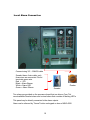
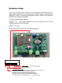
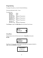
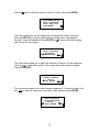
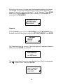
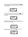
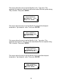
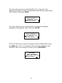
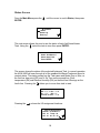
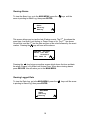
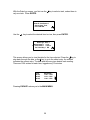
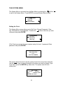
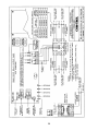
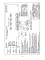
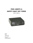
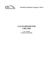
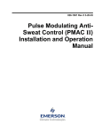
User’s Manual Anti-Sweat Heater Control Panel Picture of controller Model ASW - 4500 Com-Trol 2000 All Rghts Reserved Table of Contents Introduction Table of Contents Component Identification Introduction Installation Component Description Mounting the ASW-4500 Page 3 4 3 54 InstallationConnecting 120VAC Power Mounting the ASW-4500 Connecting 120V Power Heater circuits Connecting Anti-Sweat Connecting Anti-Sweat Heater Power Analog Input Connections Analog Input Connections Connecting the RS-485 Bus Communications connections Hardware Set-up Local Alarm Connections Programming Hardware setup 6 5 7 8 9 10 11 Programming Set-up 12 Setpoints 14 Status 18 Alarms 19 Logged Data 19 System Menu Setting Clock 21 Changing Passwords 22 Clearing Logging Memory 23 Clearing Memory 24 System Calibration 25 Appendix Solid State Relay Card Analog Input Card) 27 28 2 Introduction Effective anti-sweat heater control is necessary in today’s high energy cost market. Supermarket fixtures use anti-sweat heaters to prevent moisture from condensing on surfaces where refrigerated air meets ambient or store air. Proper store temperature and humidity are necessary for the anti-sweat heaters and their controller to be energy efficient. The Com-Trol ASW-4500 has been specifically designed to operate solid state relays through its pulsed output board. The ASW-4500 is a microprocessor based control system which uses Com-Trol’s exclusive anti-sweat heater control strategy from their software/firmware library. The ASW-4500 will control, monitor, and alarm up to 4 separate anti-sweat heater circuits (Tasks). All four tasks use a common relative humidity (RH) sensor and zone temperature sensor. Each task may have separate setpoints. This depends on the application and store environment. The ASW-4500 logs the last 71 days of readings for each task at 10 minute intervals and the last 40 alarms. The ASW-4500 connects to the Anti-sweat Control Panel via the RS-485 communications (Local) bus. The ASW-4500 has a 4 line by 20 character display and 20 character touch keyboard for easy set-up and use. It has a flashing set of LED’s which remain on until all alarms are clear and a buzzer that may be silenced by touching CLEAR on the touch pad. Two alarm outputs are provided to drive a remote audible (SONALERT) alarm and a visual alarm (flashing LED’s). The HELP key provides information for each screen, reducing the need for a reference manual. The ASW-4500 is a standalone device and may be networked with Com-Trol’s COM-5000 or ADV-6000 for remote communications. 3 Component Identification Solid State Relays Cooling Fans ASW – 4500 Controller 12VAC Controller Power Connection Analog Input Card Solid State Relay Output Card Terminals for Sensor Inputs Terminals for Local Bus Communications Terminals for Antisweat Heater Circuits from Circuit Breaker Panel Terminals for Remote Outputs 4 Controller & Card Low Voltage Transformers 120VAC Power Terminals for Antisweat Heater Circuits to Refrigerated Cases Installation The installation of the ASW-4500 is quite simple, mount the unit, Connect 120VAC and anti-sweat heater power. Connect sensor inputs and RS-485 Bus if remote communications are desired. Use “Components Identification” page as a guide. Mounting the ASW-4500 31.5” 24.5” Normally the ASW-4500 unit would be mounted in or near the compressor room. However, since this is a standalone device it can be mounted anywhere within the facility where convenient. Four .50” mounting holes are provided. See picture for mounting hole dimensions. Allow 28” clearance for door opening. Overall control panel size with door : 28.00” W 5 x 35.25” H x 5.25” D Connecting Power Connect 120VAC to these terminals. Be sure panel is grounded. The ASW-4500 requires 1 amp and should be connected to a 15 amp/120v circuit breaker that is a dedicated power source for the ASW-4500. . Use #14 copper clad conductors with a minimum of 75*C rated insulation. To prevent damage and to ensure proper operation be sure to connect grounding wire to lug provided. 6 Connecting Anti-Sweat Heater Circuits Connect 120VAC anti-sweat circuits from circuit breaker panel. 24 terminals available Connect to anti-sweat heater circuits in refrigerated cases. 16 amps maximum for each circuit The Anti-Sweat Heater Circuit terminal strips are divided into two sections. The terminal strip on the left is for 120VAC coming from the circuit breaker panel. The terminals on the right are for anti-sweat heater power to the refrigerated cases. Maximum continuous current for each circuit is 16 amps. A total of 24 circuits are available. Use #10 copper clad conductors with a minimum of 75*C rated insulation for each anti-sweat circuit. 7 Analog Input Connections Connect using 5/C – 22AWG cable. Relative humidity sensor & zone temperature sensor The analog inputs include a relative humidity (RH) sensor and a zone temperature sensor. Both sensors can be in the same enclosure. The ASW-4500 will control up to 4 separate anti-sweat circuits (Tasks) All use a common relative humidity (RH) sensor and zone temperature sensor Low voltage wiring shall be class – 2 (30 volts maximum) for sensors. 8 Communications Connections Connect the RS-485 Bus using 3/C – 22 AWG cable Com-Trol 5002 If the ASW-4500 is being networked to a Com-Trol communications interface (COM-5000) or GUI (such as the Advantage 6000), simply connect the Global Bus at the ASW-4500 terminals to the Global Bus on the interface or on any other controller. Low voltage wiring only : Class – 2 (30 Volts Maximum) for RS485 communications wiring. 9 Local Alarm Connection Connect using 3/C – 22AWG cable Sonalert has a 4 wire cable, only three wires are connected. Do not terminate green wire. Red = +12V Black = Alarm Buzzer White = Alarm LED Green = Alarm Silence Flasher Sonalert Two relays are provided on the processor board that can drive a Com-Trol remote audible Sonalert alarm and a visual alarm that consists of flashing LED’s This panel may be directly connected to the alarm outputs. Alarm can be silenced by “Cancel” button on keypad on door of ASW-4500 10 Hardware Setup There are several switches that need to be set/checked on the ASW-4500. An eight position switch on the processor board controls global communications addressing, if used, and memory initialization/ clearing. Check to see that these switches are set properly as follows. Processor/ASW-4500 Dip Switches: Switches 1-5 -- only used if connected to Com-Trol global bus. Set to next available address, binary addressing. Switch 6 – not used Switch 7 & 8 can be used to clear the memory/program. 8 7 6 5 4 3 2 1 on Board Addressing : Set to next available address . Protocol : Not used Configuration (Resetting Ram) With unit powered down, set switches 7 & 8 to “on” (down), then power up at disconnect. Move switch 7 to “off” (up) position and wait for 8 seconds, then Move switch 8 to “off” (up) position and wait for 8 seconds, then Move switch 7 back to “on” (down) position and wait 8 seconds, then Move switch 8 back to “on” (down) position and wait 8 seconds, then Turn unit off then back on again at the disconnect --- configuration complete. 11 Programming To program the system, you need to know the following : How many anti-sweat circuits – 4 max. For each circuit : Begin Day End Day Day Min On Day Min On @ Day Max On Day Max On @ Nite Min On Nite Min On @ Nite Max On Nite Max On @ (time) (time) (%) (Dewpoint Temperature) (%) (Dewpoint Temperature) (%) (Dewpoint Temperature) (%) (Dewpoint Temperature) Press Escape to get to the Main Menu from the Normal Scan Screen Main Menu Status Alarm Log Data Log Setup Menu Press the down arrow until the cursor is next to Setup Menu, then press ENTER. Main Menu Setpoints System Menu Setup Menu The Password screen will come up. Type in the high level-2 password (default is 9999), then press ENTER, as indicated. Password Required Enter Password, ++++ then press Enter. 12 Use the keys to select the zone you wish to set-up, then press ENTER. S ANTI-SWEAT SETUP Aswt 1 : AntiSweat 1 Select Aswt Task, Press ENTER. The next screen gives you the opportunity to change the name of the zone. Press the HELP key to get the instructions for entering text. Help pages 2 through 7 cover this operation. Press ENTER or to secure the name change and move to the next screen. Setup AntiSweat 1 Answ1 Task Name : AntiSweat 1 (see HELP), ENTER. The next screen allows you to select the number of Outputs. 4 is the maximum. Use the to select the number. The screen shows the number available. Then push ENTER. Setup AntiSweat 1 Number of Outputs : 1 (0 to 1) Select, ENTER. The next screen allows you to select sensor assignment : Common or New. Use the to select a common or new sensor. After selection press ENTER Setup AntiSweat 1 Sensor Assignment : Common Select, ENTER. 13 By moving to this screen you have saved the preceeding selections for the task you selected. You now have the opportunity to move to another Awst task to program it. Using the you can select “Y” or “N”. Selecting “Y” then ENTER allows you to program additional Awst tasks. Selecting “N” then ENTER will return you to the MAIN MENU. ANTI_SWEAT SET-UP Task values saved. More Aswt Tasks? Y Select, ENTER. Setpoints Pressing ENTER returns you to the MAIN MENU. From the MAIN MENU press the down arrow until the cursor is next to the SETPOINTS MENU. Press ENTER MAIN MENU Alarm Log Data Log Setpoints The Password screen will come up. Type in the high level 2 password (default is 9999), then press ENTER, as indicated. Password Required Enter Password, ++++ then Press ENTER. The next screen allows the user to select the Aswt circuit (1to 4) to set setpoints. Use to select circuit. Then press ENTER. SETPOINTS Aswt 1 : AntiSweat 1 Select Aswt Task, Press ENTER. 14 This screen allows the user to set the Begin Day time. Using the move the cursor under the digit you want to enter. Then press the number, continue moving the cursor and entering numbers until the Begin Day time is entered. Then press ENTER. SETPOINTS Aswt1: AntiSweat 1 Begin Day: 0:00 Type value, ENTER. This screen allows the user to set the End Day time. Using the move the cursor under the digit you want to enter. Then press the number, continue moving the cursor and entering numbers until the End Day time is entered. Then press ENTER. SETPOINTS Aswt1: AntiSweat 1 End Day: 0:00 Type value, ENTER. This screen allows the user to set the Day Min % On. Type value. This represents the minimum value (%) of anti-sweat heaters that can operate during “Day” schedule. Then press ENTER. SETPOINTS Aswt1: AntiSweat 1 DayMin%On: 0:00% Type value, ENTER This screen allows the user to set the Day Min On at a specified dewpoint temperature. Type dewpoint value. Then press ENTER. SETPOINTS Aswt 1: AntiSweat 1 Day Mn@DwPt: 00:0f Type Value, ENTER. 15 This screen allows the user to set the Day Max % On. Type value. This represents the maximum value (%) of anti-sweat heaters that can operate during “Day” schedule. Then press ENTER. SETPOINTS Aswt1: AntiSweat 1 DayMax%On: 0:00% Type value, ENTER This screen allows the user to set the Day Mx On at a specified dewpoint temperature. Type dewpoint value. Then press ENTER. SETPOINTS Aswt 1: AntiSweat 1 Day Mx%DwPt: 00:0f Type Value, ENTER. This screen allows the user to set the Nite Min % On. Type value. This represents the minimum value (%) of anti-sweat heaters that can operate during “Nite” schedule. Then press ENTER. SETPOINTS Aswt1: AntiSweat 1 NiteMin%On: 0:00% Type value, ENTER This screen allows the user to set the Nite Min On at a specified dewpoint temperature. Type dewpoint value. Then press ENTER. SETPOINTS Aswt 1: AntiSweat 1 NiteMn%DwPt: 00:0f Type Value, ENTER. 16 This screen allows the user to set the Nite Max % On. Type value. This represents the maximum value (%) of anti-sweat heaters that can operate during “Nite” schedule. Then press ENTER. SETPOINTS Aswt1: AntiSweat 1 NiteMax%On: 0:00% Type value, ENTER. This screen allows the user to set the Nite Mx On at a specified dewpoint temperature. Type dewpoint value. Then press ENTER. SETPOINTS Aswt 1: AntiSweat 1 Nite Mx@DwPt: 00:0f Type Value, ENTER. This screen allows you to change the setpoints of other AntiSweat tasks. Using the enter Y or N . If Y is entered it will let you enter setpoints for other AntiSweat Tasks. If N is entered it will return you to the MAIN MENU. SETPOINTS Aswt 1: AntiSweat 1 More Aswt Tasks? Y Select, ENTER. 17 Status Screen From the Main Menu press the ENTER. until the cursor is next to Status, then press M ain Menu Status Alarm Log Data Log The next screen allows the user to see the status of each AntiSweat Heater Task. Using the select the task to view then press ENTER . ANTI-SWEAT STATUS Aswt1: AntiSweat 1 Select Aswt Task, Press ENTER. This screen shows the status of the selected Antisweat Task. In normal operation the ASW-4500 will scan through all of the enabled AntiSweat Tasks and show its content status. The status screen has the Task name and Mode, Day or Nite, on the first line; dew point (DP) and % On Time on the second line; Zone temperature (ZN) and Relative Humidity (RH) on the third line & Savings on the fourth line. Pressing the allows you to move from task to task. AntiSweat 1 Day DP: ****** % On: ****% Zn : ****** RH: ***** Current % Save: ****% Pressing the . shows the I/O assignment locations. Task I/O Assignments Aswt # 1: Antisweat 1 RH: 01 Temp: 02 AO: 01 00 00 00 18 Viewing Alarms To view the Alarm Log, go to the MAIN MENU, press the arrow is pointing to Alarm Log, then press ENTER. keys until the MAIN MENU Status Alarm Log Data Log This screen allows you to view the last 40 alarm events. The 2 nd line shows the event type: Lost Aout, Lost Analog, or Power Down or Up. The 3 rd line shows Occurred at, and the 4 th line the date and time of the event followed by the event number. Pressing the keys will scan all the alarms. ASW-4500 Sys Event Alarms: Lost Aout Occurred at 07/03 09:20 #1 Pressing the key brings up another screen which shows the time and date the alarm Cleared, or In Alarm until it does Clear. When done viewing alarms press ESCAPE this will return you to the MAIN MENU. Viewing Logged Data To view the Data Log, go to the MAIN MENU, press the is pointing to Alarm Log, then press ENTER. MAIN MENU Status Alarm Log Data Log 19 keys until the arrow With the Data Log screen, you first use the only one task. Press ENTER. key to select a task, unless there is DATA LOGS Aswt #1: AntiSweat 1 Select Aswt Task, Press ENTER. Use the key to select the desired item to view, then press ENTER. Data Logs Aswt 1 Anti-Sweat 1 % On Anti-Sweat 1 % Save Rel. Humidity 1 RH This screen allows you to view the data for the item selected. Press the key to step back through the data, or the key to go to the oldest entry. An asterisk indicates the newest entry. The date and time are given beside each reading. There are 1024 entries for each item, logged every 10 minutes. %On 80.0% 80.0% 80.0% AntiSweat 1 11:20 07/03* 11:10 07/03 11:00 07/03 Pressing ESCAPE returns you to the MAIN MENU. 20 THE SYSTEM MENU The System Menu is accessed from the Main Menu by pressing the until the is next to the System Menu. Press ENTER to access System Menu screen. MAIN MENU Data Log Setpoints System Menu Setting the Clock The System Menu screen allows you to Set Clock, Change Passwords, Clear Log, Clear Memory and Calibration. Position the next to the item you wish to access, then press ENTER. SYSTEM MENU Set Clock Passwords Clear Log If Set Clock is accessed, this area requires entry of a level –1 password. Enter password, then press ENTER. Password Required Enter Password, ++++ then Press ENTER. This screen allows the user to set the system clock to the current time and date. Use the keys to move to the date or time item you want to change. Type in the value, press the ENTER key when done. The system uses 24 hour / military time. SET CLOCK 07 / 03 / 01 12:45:16 Use to Select, press ENTER when done. 21 Changing Passwords After the System Menu appears, press Passwords, then press ENTER. keys until the is next to SYSTEM MENU Set Clock Passwords Clear Log Access to Passwords requires entry of a level-1 password. Type In password, then press ENTER. Password Required Enter Password, ++++ then press ENTER. As a secondary protection a change code is required for the passwords. This code is 1843. Type in the code, then press ENTER. Change Code Required Enter Change Code, ++++ then press ENTER. This next screen allows you to change the passwords for levels 1& 2. Press the keys to select the level in which to change the password. Use the to move the cursor then type in the new password, then press ENTER. PASSWORDS Level 1 : 8888 Level 2 : 9999 Change & Press ENTER 22 Note: Make sure you do not forget the password as the only way to get back to a known password is to clear the memory on the ASW-4500 and do the complete set-up over again. Clearing Logging Memory The logging memory on the ASW-4500 can be cleared by accessing the Clear Log item on the System Menu. From the System Menu align the next to Clear Log, then press ENTER. SYSTEM MENU Set Clock Passwords Clear Log Access to this area requires entry of a level-1 password. Enter password, then press ENTER. Password required Enter Password ++++ then press ENTER. This screen will clear all logging memory. Pressing ENTER will clear all memory. If you not not want to clear memory, then press ABORT. CLEAR LOGGING MEMORY To clear log press ENTER or, ESCAPE to ABORT. 23 Clearing Memory The memory on the ASW-4500 can be cleared, if required. In normal operation this function should not be used. This action should only be taken if you are instructed to do so by Com-Trol personnel. From the System Menu align the next to Clear Memory then press ENTER. SYSTEM MENU Passwords Clear Log Clear Memory This function requires the entry of the level 2 password. Type in the password and press ENTER. Password Required Enter Password ++++ then Press ENTER. This screen gives you a warning that you will wipe out all programming and the set-up will have to be performed again. Pressing Enter again will activate the memory clear function or you can press Escape to abort the process. --=*[ WARNING ]*=-ENTER will wipe-out SET-UP memory, press ESCAPE to Abort. 24 System Calibration All field installed sensors may have to be calibrated after they are installed. From the System Menu align the next to Calibration, then press ENTER. SYSTEM MENU Clear Log Clear Memory Calibration Access to this area requires entry of a level-1 password. Enter password, then press ENTER. Password Required Enter Password ++++ then Press ENTER. The Calibration Offsets are used to adjust the Zone temperature and Humidity sensor readings based upon an accurate calibration reference. The sensors are normally very accurate, so make sure that calibration is really required before proceeding. The offset value entered is added or subtracted from the sensor reading prior to displaying or using for control. This screen allows you to calibrate the Rel-Humidity (RH1) sensor. Enter the RH% offset, then press ENTER. Rel-Humidity (RH1) Calibration Offset : Offset: 0.0% Type value, Enter. Pressing the will display the screen to calibrate the Zone temperature sensor. Enter the Zone temperature offset in *f., then press ENTER. Zone Temperature (Zn1) Calibration Offset: Offset : 0.0*f Type value, ENTER. 25 26 27