1
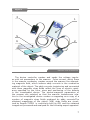
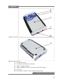
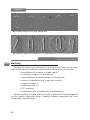
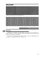
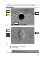
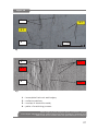
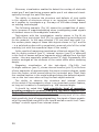
Certified Quality
Management System
MAGNETO-OPTICAL DEVICES
For nondestructive investigation of the metal surface
EDDY-CURRENT MAGNETOGRAPHING DEVICE
OF THE METAL SURFACE REGULA model 7515
For MODs REGULA model 7505M
Operating Manual
2010
2
CONTENTS
INTRODUCTION . . . . . . . . . . . . . . . . . . . . . . . . . . . . . . . . . . . . 4
1 DESCRIPTION AND OPERATION. . . . . . . . . . . . . . . . . . . . . . . . 5
1.1 Device function. . . . . . . . . . . . . . . . . . . . . . . . . . . . . . . . 5
1.2 Technical characteristics. . . . . . . . . . . . . . . . . . . . . . . . . . 5
1.3 Device composition. . . . . . . . . . . . . . . . . . . . . . . . . . . . . 6
1.4 Structure and Operation of the Device. . . . . . . . . . . . . . . . 6
1.5 Means of Measurement, the Tool and Accessories. . . . . . . 13
1.6 Marking. . . . . . . . . . . . . . . . . . . . . . . . . . . . . . . . . . . . 16
1.7 Packing . . . . . . . . . . . . . . . . . . . . . . . . . . . . . . . . . . . . 17
2 INTENDED USE . . . . . . . . . . . . . . . . . . . . . . . . . . . . . . . . . . 18
2.1 Operating limitations. . . . . . . . . . . . . . . . . . . . . . . . . . . 18
2.2 Preparation for use. . . . . . . . . . . . . . . . . . . . . . . . . . . . 19
2.3 Device use. . . . . . . . . . . . . . . . . . . . . . . . . . . . . . . . . . 19
3 TECHNICAL MAINTENANCE. . . . . . . . . . . . . . . . . . . . . . . . . . 30
3.1 General instructions . . . . . . . . . . . . . . . . . . . . . . . . . . . 30
3.2 Safety measures. . . . . . . . . . . . . . . . . . . . . . . . . . . . . . 31
3.3 Operational Serviceability Check. . . . . . . . . . . . . . . . . . . 31
4 ROUTINE REPAIRS. . . . . . . . . . . . . . . . . . . . . . . . . . . . . . . . 32
4.1 Safety Measures. . . . . . . . . . . . . . . . . . . . . . . . . . . . . . 32
4.2 General Instructions . . . . . . . . . . . . . . . . . . . . . . . . . . . 32
4.3 Instructions on Repair. . . . . . . . . . . . . . . . . . . . . . . . . . 32
5 STORAGE . . . . . . . . . . . . . . . . . . . . . . . . . . . . . . . . . . . . . . 33
6 TRANSPORTATION . . . . . . . . . . . . . . . . . . . . . . . . . . . . . . . . 34
7 RECYCLING. . . . . . . . . . . . . . . . . . . . . . . . . . . . . . . . . . . . . 35
8 ACCEPTANCE CERTIFICATE. . . . . . . . . . . . . . . . . . . . . . . . . . 36
9 SALES CERTIFICATE. . . . . . . . . . . . . . . . . . . . . . . . . . . . . . . 37
3
INTRODUCTION
The present Operating Manual (OM) is the main operational document
for the eddy- current magnetographing device (hereinafter referred
to as the “device”) of magneto-optical devices (MODs) Regula 7505M
for identification and detection of falsification of vehicle units’ numbers and vehicles documents.
The OM contains the information on the device and its components
design, principle of operation and characteristics. It also provides instructions on the correct and safe use of the device (intended use,
technical maintenance, simple routine repairs, storage and transportation) and on its technical condition evaluation when establishing
the necessity to send the device for repairs.
4
1
1.1
DESCRIPTION AND OPERATION
Device function
The device of eddy-current magnetographing is designed for carrying out investigations of the surface of the devices made of electro-conductive materials and sensitivity increase of magnetographing
process (magnetic copying) in the superficial layers of ferromagnetic
devices. The device is viewed as an add-in module of the Regula
7505M intended for magneto-optical visualization of VINs when carrying out forensic investigations.
The device use enables to investigate marking indications
on the data carriers of aluminum alloys (silumin bodies of the blocks
of cylinders and reducers, manufactory’s aluminum plates, duraluminium bodies) and increase abilities of the Regula 7505M when investigating weak signals in the superficial layers of ferromagnetic
devices, e.g. – residual (accumulated) tension.
1.2
Technical characteristics
Basic technical characteristics of the device:
Scanner supply voltage
Current in scanner conductor (peak value)
24 V
90-110A
Magnetic field tension on the scanner conductor
surface (peak value)
30-35 kA/m
Nonflatness of investigated surface
max 0.5 mm
Scan rate, max
Effective width of copying, max
50 mm/s
20 mm
Time of continuous work (without recharge), min
40 min (≈120 copies)
Type of Accumulator (ACC) batteries (set of 2
nickel-metal-hybrid ACC, 8.4V x 170mA per hour)
GP17R8H
Charge time of ACC (charge current, max 24mA)
≈8 hour
Design life of the device, min
5 years
Design life of ACC, min
Overall dimensions of scanners
500 charge cycles
30x45x70 mm
5
Controller overall dimensions
160x100x30 mm
Overall dimensions of charging unit
100x80x30 mm
Al-scanner weight
160 g
Fe-scanner weight
210 g
Controller weight
300 g
Charging unit weight
150 g
Climatic conditions of operation and storage are in conformity with the
technical requirements of Regula 7505M.
1.3
Device composition
Device set composition (Fig.1):
Controller (1)
pos.1
AL-scanner (1)
pos.2
Fe-scanner (1)
pos.3
ACC (2)
not shown in the Figure
Charging unit of ACC (1)
pos.4
Test-object No1 (Al) (1)
pos.5
Test-object No 2 (Fe) (1)
Device Operating Manual (OM)(1)
1.4
pos.6
not shown in the Figure
Structure and Operation of the Device
The device consists of 2 basic structural elements (Fig.2):
the controller and the scanner. Scanners are specialized according to
the type of the investigated material. Thus, there is Al-scanner for
electro-conductive non-ferromagnetic materials and Fe-scanner for
ferromagnetic materials in the device set. Two ACC are the power
supply source of the device controller. These batteries are charged
by a subsidiary charging unit. Device function control is carried out
in the composition of Regula 7505M using test-objects No1 and No2.
Magnetographing with the use of the device consists in the successive execution of a number of operations. The magnetic tape
is demagnetized, placed and fixed on the investigated surface beforehand. The scanner corresponding to the investigated material type
is connected to the device controller. The device controller power supply
is activated and the scanner is moved along the investigated surface.
6
Figure 1
3
1
5
6
2
4
External view of the device
The device controller creates and sends the voltage impulses with set parameters to the scanner. Pulse current, which flows
in the scanner conductor, creates around the scanner the alternating magnetic field, which induces eddy currents in the conductive
material of the object. The eddy currents trajectories and connected
with them magnetic stray fields reflect the lines of electric resistance specified by the form, sizes and positioning of the defects
in the investigated device. The electro-magnetic parameters of
the scanner are selected so that the scanner transference relative to the investigated device creates a magnetog as a copy of a
number of magnetic stray fields produced by eddy currents.The
obtained magnetogs of the object (VIN) stray fields are visualized by Regula 7505M in conformity with its OM, and the obtained
images are processed and analyzed for the following expert appraisal.
7
Figure 2
Device Scanner
Device
Controller
Storage batteries
Charging Unit of
Controller
(converter
≈220V/=24V)
Stray field’s record (magnetogram)
Object (VIN)
Surface
Magneto-optical
device (MOD)
Regula 7505M
Structural scheme of the device as a part of MOD
External view of the device controller with the basic controls
of indication and commutation is shown in Fig.3:
The device controller (Fig.3) is designed in the form of a printedwiring plate and is located in the metal body (pos.1). The controller
side slab has a socket for the connection of scanner (pos.2), and
ACC charging device (pos. 6) and its bottom side slab has ACC cells
(pos.5). The power supply tumbler (pos.3) and state indicators of the
controller and ACC charge (pos.4) are located on the front panel of
the controller body.
During the operation the device controller creates and sends voltage impulses with set parameters to the scanner. These parameters
correspond to the type of the connected scanner. Moreover, the controller carries out self-diagnostic, controls ACC charge and provides
its additional charge (if the ACC charging device is connected).
8
Figure 3
3
4
1
2
6
а) the top view
5
b) the bottom view
1 - Controller body
2 - Connection socket of scanners
3 - Power supply tumbler
4 - State indicators of the controller and ACC charge
5 - ACC cell
6 -Connection socket of the network power unit
External view of device controller
9
When the scanner socket (pos.2) is connected and power supply
is activated by the device controller tumbler (pos.3), the indicators
(pos.4) may have the following states:
Only the green indicator glows – controller state and ACC
charge are normal
The green indicator glows and the red indicator blinks
impulsively – ACC charge is needed
The green indicator blinks impulsively showing failure
in the controller prog. This situation can occur
as a result of the repeated activation without a temporal
pause (15-20 sec) from the time of previous deactivation, as well as due to the scanner socket closing/opening when the controller power supply is activated. You
can restart of the controller when the power supply
is deactivated and a temporal pause of 15-20 sec is made.
Neither of LED glows – ACC are absent or are fully discharged, the device controller malfunction.
When the ACC charging device is connected to the controller device and its power supply is connected to the mains 220V, the yellow indicator may glow. The glowing means the presence of external
power supply controller (=24V) at the input, which provides an additional charge of the ACC including the charge during the device
operation process.
The access to ACC for their charge and replacement is carried
out by loosening 4 screws and removing the trays’ cover (pos.5).
External view of AL-scanner is given in Fig.4.
The device Al-scanner (Fig.4) is designed in the form of a printedwiring plate and is located in the plastic body (pos.1). The conductor of eddy currents Inductor (pos.2) is placed in the slot of dielectric clamping elements (pos.3) which move free relative to the body
(pos.1) and are elements of the conductor tension system (pos.2).
Scanner’s body (pos.1) has a relief mark (pos.4) in the form of
the stylized arrow, indicating the scanning direction. The scanner
is connected to the controller through the socket installed
on the cable (pos.5).
During the operation the scanner by means of the cable (pos.5)
is connected to the device controller which forms and sends voltage
impulses with set parameters to the scanner. Pulse current, which
flows in the scanner conductor (pos.2), creates around it the alternating magnetic field which induces eddy currents in the electroconductive material of the object. For magnetographing the scanner
is transferred along the investigated surface on which the demagnetized magnetic tape is preliminary fixed.
10
Figure 4
1
3
5
scanning direction
2
4
1 - Scanner body
2 - Conductor of eddy currents Inductor
3 - Clamping elements
4 - Relief tag of scanning direction
5 - Cable for connection to the controller
External view of Al-scanner
In case of magnetographing of the relief surface, the clamping elements (pos.3) deform the conductor (pos.2) in conformity
with the current relief profile. In the scanning process the slot of dielectric clamping elements (pos.3) functions as the conductor protection (pos.2) from mechanical damage and dirt.
11
Figure 5
1
3
5
scanning direction
2
6
7
4
1 - Scanner body
2 - Conductor of eddy currents Inductor
3 - Clamping elements
4 - Relief tag of scanning direction
5 - Cable for the connection to the controller
6 - Front polar tip of magnetization system
7 - Back polar tip of magnetization system
External view of Fe-scanner
12
External view of the device Fe-scanner is given in Fig.5.
The device Fe-scanner (pos.5) elements are similar in their design
to those of Al-scanner pos.1-5 (see description of Fig.4). The specialty of the given type of the scanner is the magnetization system which
includes the source of the continuous magnetic field (not shown in
the figure), magnetic conductors with polar tips (pos.6, 7).
During Fe-scanner operation the elements (pos.1-5) function analogously to Al-scanner (see description of Fig.4). The magnetization system is used to excite the magnetic stray fields of the defects located in
the sub-superficial layers of the ferromagnetic device. In the process of
magnetic copying the polar tips of the magnetization system (pos.6, 7)
must contact close the magnetic tape and the investigated surface.
1.5
Means of Measurement,
the Tool and Accessories
The Regula 7505M (magneto-optical device TC.Uk 33.214361144.001.2003) belongs to the category of displaying (not
measuring) devices. According to it, means of function control of
the Regula 7505M and the device as its component are executed as
test-objects, simulating the widespread modified changes of vehicle
VINs (pouring by polymers, pressing in fragments, and removal of
the metal superficial layer). The control order of serviceability of the
device with the use of test-objects is described in detail in paragraph
2.1.3. of the Regula 7505M OM and 3.3 of the given OM.
Characteristics of the test-object of the device:
Test-object No1 (Al) (Fig.6) is the imitator of Category “A” control
object (the data carrier of the vehicle body). It is executed in the
form of a plate made of a sheet of aluminum alloy with the thickness
of 1mm bearing “29165” initial number applied by the method of
machining process (cold pressing). The initial number was made in
the following way: manual stamping with use of “No.10 type” markers kit and hammer on a massive anvil. The depth of digits relief
makes about 0.4 mm.
Three digits of the initial number were modified as follows: “9”
by “0”, “6” by “9” and “5” by “7”. Thus, the modified new number appears as “20197” (the modified digits are underlined).
Digit “9” in the initial number was modified manually using
cold calking of the element (bulkhead) of digit “9” with the help
of a bench tool and then stamping of the new digit “0” over the remaining contour of digit “9”.
13
Digit “6” in the initial number was modified in the following way:
dismantling (cutting-out) of the initial number fragment bearing digit
“6” with the help of a blanking tool, swap (180° rotation), pressing
in of the cut-out fragment with digit “6” (thus digit “6” is transformed
into digit “9”).
Digit “5” in the initial number was modified manually using
the process of pouring of the digit relief by polymer (epoxy spackling); stamping of the new digit “7” over soft spackling.
Figure 6
Photo image of the investigated surface
of the test-object No1 (Al)
After the digits of the initial number were modified, the following
operations were executed on the test-object: scraping; spackling;
priming; two-layer tinting with aerosol motor enamel using cold drying using technology corresponding to repairs coating.
Test-object No2 (Fe) (Fig.7) is the imitator of Category “A” control object (the data carrier of the vehicle body). It is executed
in the form of a plate made of a sheet of tool steel with the thickness of 2mm bearing “29165” initial number applied by method of
machining process of pressing (cold pressing). The initial number was
made in the following way: manual stamping with use of “No.10 type”
markers kit and hammer on a massive anvil. The depth of digits relief
makes about 0.3-0.4 mm.
All digits of the initial number were removed by the way of removing of the metal superficial layer of the test-object to the depth
of 0.5 mm. The removal of the superficial layer from the initial marking
is executed by the method of machining process of cutting (milling
and polishing).
As a result of the mentioned process of the test-object surface, the initial marking is not observed by visual-optical methods
(as the relief is removed). However, internal residual tension, produced as a result of deformation of the metal when executing
the initial marking, is in the superficial layer of the test-object metal.
14
Figure 7
Photo image of the investigated surface
of the test-object No2 (Fe)
Function control
Take out the test-objects of the device and execute their
magnetic copy as described in paragraph 2.3;
Perform magnetic copy stitching in the PC as described
in paragraph 2.2.1.3 of the Regula 7505M OM;
Compare results of the obtained magnetic copies stitching with the control images, shown in Figure 8 and Figure 9. In case comparison results are positive, the device
operation is considered as normal. Criteria of comparing the results of the obtained magnetic copy stitching
with control images for Al-scanner are as follows:
——compare the quality of processing of the alteration
sings of the initial number digits (the contours traces
of the initial marking digits on the 2th and 6th digit position and fragments pressing-in contours on the 4th
digit position as well as the traces of machining process on the 4th and 6th digit position shall be visible)
——compare the quality of processing of the digits
of the secondary number (the contours of all digits
shall be visible)
Criteria of comparing the results of the obtained magnetic copy stitching with control images for Fe-scanner
are as follows:
——compare the quality of processing of the digits contours of the remote initial number (the contours outlines of all digits shall be visible)
——in case of malfunction during any of the function control stages see paragraphs 3 and 4.
15
Figure 8
а) surface image of the test-object No1
b) magneto-optical visualization of magnetogram of the test-object No1
Function control of the device
with the use of Al-scanner
1.6
Marking
The device marking is executed in the form of a label on the back
side of the device controller and provides information as follows:
manufacturer’s name or trade mark;
symbolic notation of the device;
manufacturer’s serial number of the device;
date of manufacturing (year and month);
rated voltage, V;
rated current, A;
TC marking;
national mark of conformity (certification);
Device sealing is made with the help of destructive labels applied
on the device controller body. Sealing violation deprives the User
of warranty maintenance.
16
Figure 9
а) surface image of the test-object No2
b) - magneto-optical visualization of magnetogram of the test-object No2
Function control of the device
with the use of Fe-scanner
1.7
Packing
Packing the hardware of the device is carried out at regular accommodation in a case, and the SPCS (Spare Parts and Components
Set) is in the bag for the SPC.
The device is transported and stored in a special packaging box
(wooden or cardboard) of the delivery set.
17
2
2.1
INTENDED USE
Operating limitations
IT IS STRONGLY PROHIBITED TO:
——Disconnect the scanner socket if the indication
of the controller power supply is present.
——I.e. it is prohibited to disconnect the scanner
if the power supply tumbler is activated as well
as within 15-20 sec after its deactivation
——use other charging units of the ACC different from the
stipulated ones
——use faulty network sockets and power supplies
for ACC charge
——turn on the equipment with apparent damages of protective isolation and conductors
——turn on the device when protective shrouds are removed
The User should observe the following operating limitations of the device:
Consider climatic operational conditions as described
in paragraph 1.1.1of the Regula 7505M OM. The device
should not be used under the rain out-of-doors or out
of the passenger compartment. In case water or condensate appear on the body of the device elements, the
device operation shall be stopped and can be renewed
only after drying;
working operating conditions regarding mechanical influences are not specified. The device should not be exposed to impacts and strong vibration when operating
and transporting;
observe quality norms for power supplies, see paragraph
1.1.2.4 of the Regula 7505M OM;
all commutations of the device components connected
with opening and closing of electric sockets shall be carried out with deactivated power supply of the device.
Violation of operating limitations under paragraph
2.1 by the User leads to the loss of the manufacturer’s warranty.
18
Using limitations:
it is possible to investigate only electro-conductive materials when the scanner type is chosen correctly
it is not allowed to operate the device with damaged
(through break with sharp edges, heavily crushed), bent
on edges and polluted magnetic tapes (see paragraphs
2.2.2.2 and 3.2.2 of the Regula 7505M OM. Failure to observe these requirements may result in discrepancies during stitching and jamming of magnetic tapes in the МОD
when using the device on the surfaces with nonflatness
more than 0.1 mm on the basic area of 18x20mm or
roughness more than Rz 80µm, the quality of the magnetic copy is not guaranteed due to significant contact losses
recharge ACC according to 3.1 at least once in 2 months
2.2
Preparation for use
Activation order:
Choose the scanner corresponding to the type of the investigated material: Fe- scanner for ferromagnetic materials (steel, cast iron); Al-scanner for non-ferromagnetic
electro-conductive materials (nonferrous metals and
their alloys)
Connect the chosen scanner (Fig.1, pos.2 or pos.3)
to the controller socket (Fig.1, pos.1)
Turn on the power supply tumbler of the device controller (Fig.3, pos.3) and make sure that ACC are charged
enough according to the state of indicators (Fig.3, pos.4)
as described in paragraph 1.4. If it is necessary, charge
ACC under paragraph 3.1
Turn off the power supply tumbler of the device controller (Fig.3, pos.3)and carry out the operations necessary
to start magnetographing under paragraph 2.3
Turn on the Regula 7505M in conformity with paragraph
2.2 of the Regula 7505M OM.
2.3
Device use
Device operation on execution of the object magnetic copy requires the execution of the following operations:
Preparation of the investigated surface as described
in paragraph 2.2.2.3 of the Regula 7505M OM
Preparation (demagnetization) of the magnetic carrier as
19
described in paragraph 2.2.2.3 of the Regula 7505M OM
Magnetic copy execution
WARNING!
THE DEMAGNETIZATION PROCESSES OF THE MAGNETIC
CARRIER AND MAGNETOGRAPHING MUST BE COORDINATED BY THE DIRECTION (SEE FIG.10). OTHERWISE THE
MAGNETIC RECORDING WILL BE WEAK, AND IN CASE OF
WEAK SIGNALS IT CAN NOT BE EXECUTED AT ALL.
In order to prevent errors of the direction coordination, a visual
noticeable tag should be placed on the magnetic tape surface, e.g.
as is shown in Fig.10 to make a “start” point by a felt-tip pen at the
beginning of the magnetic tape.
The magnetic carrier should be demagnetized as described in paragraph 2.2.2.3 of the Regula 7505M OM. The demagnetizer must be
moved from left to right relative to the “start” point (see Fig. 10a).
The demagnetized magnetic tape is placed on the investigated
surface without overturns, i.e. so that the “start” point is always
at the left edge.
When carrying out magnetographing the demagnetizer is also
moved from left to right relative to the “start” point (see Fig.10b),
and the scanner body must be placed in the way that the relief tag
(Fig.4, pos.4) in the form of a cylindrical concavity is located under
the thumb of a right hand, i.e. behind it (in the movement direction).
Magnetic copy:
Put the magnetic tape on the prepared number area
of a vehicle and fix its end on the investigated surface by
a magnetic clamp, adhesive tape or manually (try to avoid
skewness and shifts relative to the investigated number)
Fix the same way (if it is fixed firmly at the beginning it can be left loose) the other end of the magnetic tape
stripe. The operator may choose any way of the magnetic
tape fixation
For Fe-scanner set the regulator of magnetization system
of the device scanner (Fig.4, pos.8) in its prior position
in conformity with the recommendations of paragraph 1.4
Place the body of the device scanner in the way that
the relief tag (Fig.4, pos.4) in the form of a cylindrical
concavity is directed to the “start” point (Fig.10b). Put
the scanner on the fixed stripe of the magnetic tape,
make sure they have a tight contact with the investigated
surface and pass slightly pressing it down from begin-
20
Figure 10
а) demagnetization, demagnetizer movement from left to right
b) - magnetographing, scanner movement from left to right
Coordination of the processes of demagnetization
and magnetographing by the direction
ning to end of the investigated area. It is recommended
to use scanning rate not exceeding 50mm/s, as otherwise the magnetic bias signal will be recorded on the tape
(in the form of vertical black-white stripes). In order
to obtain a high-quality copy the operator has to control
tactually and visually its abutment to the investigated
surface. If the copying terms are violated (magnetic tape
21
shift, noncontact or scanner run-off), repeat all operations starting from the magnetic tape demagnetization
Take the magnetic tape with the copy off the investigated object and disconnect the clamps. When executing
the given operation avoid the contact of the magnetic
clamps and the scanner with the magnetic tape surface
in the area of the magnetic copy execution. Otherwise
the magnetic copy can be partially demagnetized and
“unnecessary” elements of magnetization (spots or
stripes unrelated to the investigated object) may appear
in it, that can complicate the following investigations
Stitch the magnetogs in the USB device for magnetooptical visualization of complex Regula 7505M
Put the magnetic copy into the corresponding compartment of the magnetic tapes case (the compartment
for non-investigated magnetic copies is red marked).
If it is necessary a comment can be applied on the magnetic copy with the use of a marker from the device set
If the operative investigation of the magnetic copy
is impossible (e.g. due to lack of the visualization device), execute 1-2 safety magnetic copies more, for Fescanner – when the positions of the regulating flywheel
of the magnetization system of the device scanner (Fig.5,
pos.8) are different, that minimizes operator’s inaccuracy
when executing magnetic copying.
Examples of efficient use of the device
The result shown in Fig. 11 can be considered as an example
of the device efficient use for investigation of homogeneity
of the surface composition of the device made of aluminum alloy.
The image of the object surface in the form of a magnalium plate
of 1 mm thickness is shown in Fig. 11a. The plate contains such artificially formed relief elements and defects as:
Not specially marked through hole of 1.5 mm diameter;
holes of 0.4-1.2 mm diameter and ‘133’ impressed digital
stamp visible with the naked eye;
Well-noticeable visually parallel scratches pos.1 of 200300µm width;
Hardly-noticeable visually curved scratch pos.2 of 100
µm width;
Casually located insignificant superficial defects 3
in the form of small grey spots which correspond visually
22
to indiscernible indents, surface dirt and accumulations
of (extrinsic) ferromagnetic inclusions which embedded
in the sample surface as a result of its mechanical process.
The results of visual-optical data analysis can not help
to extract the accumulations of ferromagnetic inclusions
from a number of insignificant superficial defects pos.3.
All above-mentioned relief elements including scratches pos.1 and
pos.2 are clearly observed as a result of magnetog visualization of
the given object (Fig. 11b) and their contrast is higher than that of
the optical image. It attests sensitivity of magnetographing and visualization devices to superficial defects such as scratches of 100 µm
width and resolution not less than 200 µm.
Moreover, visualization enabled to detect by brightness and
contrast the accumulations of ferromagnetic inclusions pos.4
from a number of insignificant superficial defects pos.3.
The ability to detect superficial ferromagnetic inclusions
is an important control feature, so long as it enables to investigate
e.g. the transfer of metal (steel) microparticles from matrix and punch
to the face and back surface of an aluminum carrier of VIN data.
23
Figure 11
3?
3?
10 mm
а)
3?
3?
2
1
b)
4!
4!
1 – scratches of 200-300 µm width;
2 – scratch of 100 µm width;
3 – insignificant superficial defects;
4 – accumulations of ferromagnetic inclusions
Photo image (a) and magneto-optical visualization results
of the object magnetogram (b).
The aluminum object has a superficial ferromagnetic inclusion
24
Another example (Fig.12) shows the device abilities when investigating discontinuity flaws such as surface cracks in aluminum.
Figure 12
1
2
3?
10 mm
а)
1
2
3!
4!
b)
1 – hole of 5 mm diameter;
2 – scratches of 100-200 µm width;
3 – crack nucleus;
4 – point of crack increase.
Photo image (a) and magneto-optical visualization results
of the object magnetogram (b).
The aluminum object has a surface crack
25
The image (shown in Fig.12a) of the object surface is in the form
of a duraluminum plate of 4 mm thickness which contains such artificially formed relief elements and defects, as:
Through hole (pos.1) of 5 mm diameter as a tension concentrator;
Visually discernible curved scratches pos.2 of 100-200
µm width;
Hardly discernible with the naked eye crack nucleus pos.3
which appeared as a result of cyclical bending deformations of the sample.
All above mentioned relief elements including scratches pos.2 and
crack nucleus pos.3 are clearly observed in the results of magnetog
visualization of the given object (Fig.12b), and their contrast is higher
that that of the optical image.
Moreover, visualization enabled to detect the whole crack profile
including its increase point pos.4.
The ability to detect surface cracks is an important control feature,
so long as it enables to investigate e.g. microcracks on the surface
of an aluminum carrier of VIN data, which appear in consequence of
its plastic deformations.
The following example (Fig.13) shows the device abilities when
investigating joint welds in aluminum and their defects.
The image of the object surface is shown in Fig. 13 (a). The object
is executed of aluminum alloy and has a trimmed joint weld. The object is made of 2-sheet magnalium fragments of 2 mm thickness connected with a butt weld (arc welding). The weld surface is trimmed
with a manual abrasive tool and covered with a paint film layer of
100 µm. You can also observe visual-optically such artificially formed
relief elements and defects, as:
Incomplete fusion (pos.1) at weld edges;
curved scratches pos.2 of 100-200 µm width well- discernible with the naked eye;
However, visual-optical data do not help to establish the belonging
of the scratches pos.2 to the paint film or the metal of the sample
surface.
In the results of magnetog visualization of the given object (Fig.13b)
the incomplete fusion (pos.1) is observed at weld edges, and their detailing degree is higher, that that of the optical image. Obviously the
curved scratches (pos.2) belong to the paint film, so long as they are
absent in the results of the sample magnetog visualization.
26
Figure 13
1
2?
2?
1
10 mm
а)
1
4!
3!
1
1!
b)
1 – incomplete fusion at weld edges;
2 – surface scratches;
3 – overlap of electrode metal;
4 – paths of machining process.
Photo image (a) and magneto-optical visualization results
of the object magnetogram(b) made of aluminum alloy containing a trimmed joint
weld on the device surface under the paint film layer of 100 µm
27
Moreover, visualization enabled to detect the overlap of electrode
metal pos.3 and machining process paths pos.4 not observed visualoptically through the paint film layer.
The ability to observe the structure and defects of joint welds
in the objects of aluminum alloys is an important control feature,
as it enables to investigate e.g. the ways of VIN data change based
on welding technologies. The following example (Fig 14) shows the probabilities of sensitivity increase of magnetographing when investigating weak signals
of residual stress in ferromagnetic materials.
Test-objects with the investigation results shown in Fig.14 do
not differ from test-object No2 (Fe) by manufacturing technique but
for the material. In this case stronger Y7A tool steel was used. I.e.
the surface photo image of these test-objects shown in Fig.7 and 9a
– is a polished surface with a completely removed relief of the initial
marking (cut with the superficial layer of the metal).
In the results of magnetog visualization of the test object (Fig.14a),
but for digits contours (pos.1), internal tension (pos.2) is observed
in the form of beams and arcs segments which radiate from the digit
center – they are especially notable around “6” digit. Supposedly, this
tension emerged at the surfaces of the metal shifts when stamping
deeply.
Magnetog visualization of the test-object (Fig.14b), but
for digits contours (pos.1), shows internal tension (pos.3) in the form
of arcs segments of approximately the same curvature degree, made
from the center, which moved along the horizontal axis. Most likely
this residual tension in the metal emerged along the defects trajectories on the tool nose when milling the test-object material.
The ability to observe the structure and internal tension
of the metal of ferromagnetic alloys is an important control feature,
so long as it enables to investigate e.g. VIN removed digits.
It should be noted that high sensitivity level of magnetographing enables to control efficiently the metal internal tension only on flat and smooth surfaces. Otherwise, if the object
surface is covered with deep scratches, in consequence of the same
high sensitivity level of magnetographing, the signal of these scratches will be amplified manyfold in the record and as a result it will “camouflage” a useful signal from internal stress.
28
Figure 14
1
2!
10 mm
2!
2!
а)
1
3!
3!
3!
3!
b)
1 – digits contours of the removed relief marking;
2 – supposedly, surfaces of the metal shifts;
3 – defects trajectories on the tool nose.
Magneto-optical visualization results of the magnetograms of the test-objects of ferromagnetic alloy containing internal tension, which emerged as a result of processing
by pressure (a) and processing by cutting (b)
29
3
3.1
TECHNICAL MAINTENANCE
General instructions
Everyday technical maintenance
for the operations as follows:
of
the
device
provides
external examination (visually check the integrity
of the controls, indication and commutation, as well as the
integrity of isolation and the scanner cable conductors);
control of ACC charge is carried out by trial activation
depending on the state of the charge indications as described in paragraph 1.4. If required (indication of ACC
discharge), charge ACC in conformity with the requirements of paragraph 3.1;
cleaning of the front panel, controls and scanner surfaces
from dust and fatty films is to be carried out with a soft
tissue paper (scouring cloth) or a wad wetted in the ethyl
alcohol;
Approximate ethyl alcohol consumption per working shift makes 5 g.
Technical maintenance of the device when preparing it for storage
and in the storage mode:
place and package all device
into the transportation package;
components,
put
at least once per two months recharge ACC under
the requirements of paragraph 3.1.
Current technical maintenance of the device includes ACC recharge. The device ACC require regular recharge to prevent their
untimely failure. Recharge periodicity depends on the indication state
(paragraph 1.4), but at least once in 2 months. When charging ACC
safety measures described in paragraph 2.1 shall be observed.
Charge order of the ACC:
Connect the charging unit to the wall outlet (alternating current of 220 V, 50 Hz). If the indicators
of the charging unit are activated, there are voltage supply and contact in ACC sockets.
Wait ≈ 8 hours( till full charge). Do not interrupt charging
as it may lead to ACC capacity decrease.
Disconnect the charging unit from the wall outlet.
Carry out function control according to paragraph 2.2.
30
3.2
Safety measures
Observe safety measures as described in paragraph 2.1 when performing the device technical maintenance.
3.3
Operational Serviceability Check
For operational serviceability check see “control function” section
of paragraph 2.2.
31
4
4.1
ROUTINE REPAIRS
Safety Measures
When carrying out routine repairs, safety measures correspond
to the requirements of paragraph 2.1.1.
4.2
General Instructions
The present OM provides only one type of repairs delegated
to the User: replacement of the worked- out resource of the ACC.
4.3
Instructions on Repair
Replacement of ACC is carried out in case of significant decrease
of batteries capacity, which may happen after 500 charge cycles or
as a result of violation of the their operation and storage conditions.
In case of ACC replacement, only the analogous type of the storage
battery (GP17R8H) is permissible.
32
5
STORAGE
Device shall be stored in the manufacturer’s package.
Climatic storing conditions:
air temperature range
from +50C to +400C (discharged ACC shall be
stored at the temperature of approximately
+50C which enables to keep their characteristics
for several years
relative air humidity
up to 80% at +150C
atmospheric pressure
100 +/- 4 KPa (750 +/- 30 mm)
When preparing the device for storage, it is recommended to perform technical maintenance as described in paragraph 3.2.
Devices can be stored in the manufacturer’s package, in stacks up
to 10 items high.
33
6
TRANSPORTATION
The device can be transported in the industrial package
of the manufacturer (provided in the delivery set). Climatic storage conditions stipulated in paragraph 5 shall be provided. Protect
the device from impacts and vibrations.
34
7
RECYCLING
Recycling of the device shall be carried out in conformity
with rules adopted at the user’s enterprise. ACC and their charging
unit require special utilization rules.
35
8
ACCEPTANCE CERTIFICATE
Eddy-current magnetographing device Regula 7515
Serial number
is produced and adopted as provided by the governmental standards, technical documentaiton, and is approved as ready for operation.
Responsible for acceptance:
_________________
Seal:
(Signature)
_________________
(YY, MM, DD)
36
_________________
(First and Last Name)
9
SALES CERTIFICATE
(to be filled in by the Seller)
Eddy-current magnetographing device Regula 7515
Serial number
is sold to:
Buyer’s Name: _________________________
Seal:
Date of sale: ___________________________
Device Price: ___________________________
Manufacturer: “REGULA”, ltd.
Address for mailing claims with regard to quality of the device:
1, Voloha Street, Minsk
220036, Republic of Belarus
Phone: +375 17 286-2825
Fax: +375 17 210-2397
e-mail: [email protected]
WEB: http://www.regula.by
37
38
39
1-314, Voloha Street, Minsk, 220036, Republic of Belarus
Phone: +375 17 286-2825 Fax:+375 17 210-2397
e-mail: [email protected] http://www.regula.by
40