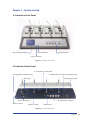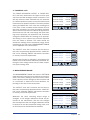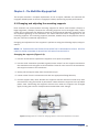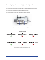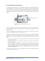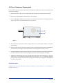
1
Multi Wire Myograph System Model 620M User Manual Version 1.0 Multi Wire Myograph System - Model 620M User Manual Trademarks Pentium is a registered trademark of the Intel Corporation. Windows, Windows 95, Windows 98, Windows ME, Windows NT, Windows 2000, Windows XP, Windows Vista, and Windows 7 are registered trademarks of Microsoft Corporation. All other trademarks are the properties of their respective owners. DMT reserves the right to alter specifications as required. This document was, as far as possible, accurate at the time of printing. Changes may have been made to the software and hardware it describes since then. New information may be supplied separately. This documentation is provided with the DMT Multi Wire Myograph System – Model 620M – Version 1.0 No part of this document may be reproduced by any means without the prior written permission of DMT. Copyright © 2010 DMT A/S DMT A/S Skejby Science Center Skejbyparken 152 DK-8200 Aarhus N Denmark DMT-Asia Rm 28C Liang Feng Building No. 8 Dong Fang Road Lu Jia Zui Financial District Shanghai 200120 P.R. China DMT-USA, Inc. 1201 Peachtree Street 400 Colony Square Suite 200-630 Atlanta, GA 30361 USA Tel.: +45 87 41 11 00 Fax: +45 87 41 11 01 Tel: +86 (0) 21 6486 9685 Fax: +86 (0) 21 5877 0063 Tel.: +1 770 612 8014 Fax: +1 678 302 7013 www.dmt.dk [email protected] [email protected] www.dmt-asia.com [email protected] [email protected] www.dmt-usa.com [email protected] [email protected] Trademarks Contents Trademarks������������������������������������������������������������������������������������������������������������������� 3 Introduction������������������������������������������������������������������������������������������������������������������ 5 Safety���������������������������������������������������������������������������������������������������������������������������� 6 EMC/EMI���������������������������������������������������������������������������������������������������������������������� 7 Approvals���������������������������������������������������������������������������������������������������������������������� 7 Certificate of Conformity��������������������������������������������������������������������������������������������� 8 About this manual������������������������������������������������������������������������������������������������������� 9 Unpacking the myograph system�����������������������������������������������������������������������������10 Chapter 1 — System overview�����������������������������������������������������������������������������������11 1.1 Interface Front Panel�����������������������������������������������������������������������������������������������11 1.2 Interface Rear Panel�����������������������������������������������������������������������������������������������11 1.3 Multi wire myograph unit����������������������������������������������������������������������������������������12 Chapter 2 — Setting up����������������������������������������������������������������������������������������������13 2.1 The Complete Myograph 620M System�����������������������������������������������������������������13 2.2 Setting up step-by-step�������������������������������������������������������������������������������������������13 2.3 The first weight calibration��������������������������������������������������������������������������������������14 Chapter 3 — The Interface Menus����������������������������������������������������������������������������15 Chapter 4 — The Multi Wire Myograph Unit������������������������������������������������������������23 4.1 Changing and adjusting the mounting supports���������������������������������������������������23 4.2 Calibration of the force transducer������������������������������������������������������������������������26 4.3 Checking the force transducer�������������������������������������������������������������������������������28 4.4 Force Transducer Replacement������������������������������������������������������������������������������29 4.5 Myograph Maintenance������������������������������������������������������������������������������������������30 Chapter 5 — Dissection, mounting and normalization��������������������������������������������32 5.1 Dissection Protocol for Small Mesenteric Arteries������������������������������������������������32 5.2 Mounting protocol for small arteries����������������������������������������������������������������������36 5.3 Normalization����������������������������������������������������������������������������������������������������������40 Chapter 6 – Experimental protocols������������������������������������������������������������������������41 6.1 Summary of procedures - start to finish����������������������������������������������������������������41 6.2 Example of step-by-step experimental procedure�������������������������������������������������43 6.3 Practice exercises����������������������������������������������������������������������������������������������������45 6.4 Buffer Recipes���������������������������������������������������������������������������������������������������������48 Appendix 1 — Terms of warranty�������������������������������������������������������������������������������51 Appendix 2 — Calibration of Eyepiece Reticule������������������������������������������������������52 Appendix 3 — Reading a millimetre micrometer�����������������������������������������������������54 Appendix 4 — Principles of weight calibration��������������������������������������������������������56 Appendix 5 — Normalization theory�������������������������������������������������������������������������58 Appendix 6 — Service Check�������������������������������������������������������������������������������������60 Appendix 7 — Shipping Instructions�������������������������������������������������������������������������61 Appendix 8 — Myograph accessories and spare parts�������������������������������������������62 Appendix 9 — System Specifications ����������������������������������������������������������������������64 Notes ��������������������������������������������������������������������������������������������������������������������������65 Multi wire myograph system Model 620M - User manual Introduction Until the mid-1970s most of the information about the mechanical, morphological and pharmacological properties of vascular smooth muscle were only obtainable from studies on relatively large vessels. At that time rat-tail arteries were the smallest vessels to be investigated in detail due to limitations in the available in vitro techniques. For example, studies measuring the contraction force were routinely performed with only one of the mounting wires secured. Futhermore, relatively large wires (100-200 μm) were used, which precluded the use of small vessels. In addition, the vessel segment had to be directly manipulated with dissecting instruments, causing mechanical trauma. Investigations of smaller vessels, therefore, were limited to in vivo perfusion experiments and histological examination. In 1976 Professor M. J. Mulvany and Professor W. Halpern described, for the first time, a new technique that made it possible to investigate highly isometric responses from vessels with internal diameters as small as 100 μm. The mounting procedure was refined in 2 ways: 1) both ends of each mounting wire were secured under tension without any direct manipulation of the vessel, and 2) segments of small vessels could not be atraumatically mounted as ring preparations in a myograph for recording of highly isometric force measurements. During the late 1970s, some improvements were made to the myograph, and in 1981, a new dual myograph that allowed simultaneous testing of two vessels was introduced. In parallel, the technique became widely acknowledged, resulting in a growing interest in the myograph systems. In 1986, the growing demand resulted in the foundation of the private company, J. P. Trading, with the purpose of making the myograph systems commercially available worldwide. At the same time, J. P. Trading initiated a comprehensive improvement programme for the existing myograph systems as well as a development programme of new myograph systems in close co-operation with Professor M. J. Mulvany and The University of Aarhus. During the late 1980s and through the 1990s, several improvements were applied to the myograph systems, such as a new mechanical design, a more robust transducer, and a new electronic system. New systems also were introduced, such as the automatic dual myograph 510A, the multi myograph 610M and the confocal myograph 120CW. In 2000, J. P. Trading changed its company structure and became known as DMT. Today, DMT is one of the world’s leading designers and manufacturers of wire myographs, pressure myographs, culture myographs and organ/tissue baths. Driven by our global customer base, our singular goal is to develop and manufacture first-class research equipment within the fields of physiology and pharmacology. Introduction Safety The 620M Multi Wire Myograph System has been designed for use only in teaching and research applications. It is not intended for clinical or critical life-care use and should never be used for these purposes, or for the prevention, diagnosis, curing, treatment, or alleviation of disease, injury, or handicap. • Do not open the unit; the internal electronics pose a risk of electric shock. • Do not use this apparatus near water. • To reduce the risk of fire or electric shock, do not expose this apparatus to rain or moisture. Objects filled with liquids should not be placed on the apparatus. • Do not block any ventilation openings. Install in accordance with the manufacturer’s instructions. • Do not install near any heat sources such as radiators, heat registers, stoves, or other equipment or devices that produce heat. • Only use attachments and accessories specified by the manufacturer. • Unplug this apparatus during lightning storms or when unused for long periods of time. • This apparatus must be grounded. • Use a three-wire grounding-type cord similar to the one supplied with the product. • Do not modify the polarized or grounding-type plug. A polarized plug has two flat blades, one being wider than the other. A grounding type plug has two blades and a third (round) grounding pin. The wide blade or the third prong is provided for your safety. If the provided plug does not fit into your outlet, consult an electrician for replacement of the obsolete outlet. • Be advised that different operating voltages require the use of different types of line cord and attachment plugs. Check the voltage in your area and use the correct type. See the table below: Voltage Line plug according to standard 110–125 V UL81 and CSA C22.2 No. 42 220–230 V CEE 7 page VII, SR section 107-2-D1/IEC 83, page C4 BS 1363 of 1984. Specification for 13A fused plugs and 240 V switched and unswitched socket outlets. Protect the power cord from being walked on or pinched, particularly at power outlets and the point where they connect to the apparatus. Refer all servicing to qualified service personnel. Servicing is required when the apparatus has been damaged in any way; such as, the power-supply cord or plug is damaged, liquid has spilled onto or objects have fallen into the apparatus, the apparatus has been exposed to rain or moisture, does not operate normally, or has been dropped. Multi wire myograph system Model 620M - User manual EMC/EMI This equipment has been tested and complies with the limits for a Class B Digital device, pursuant to part 15 of the FCC rules. These limits are designed to provide reasonable protection against harmful interference in residential installations. This equipment generates, uses, and can radiate radio frequency energy and, if not installed and used in accordance with the instructions, may cause harmful interference to radio communications. However, there is no guarantee that interference will not occur in a particular installation. If this equipment does cause harmful interference to radio or television reception (which can be determined by monitoring the interference while turning the equipment off and on), the user is encouraged to correct the interference by one or more of the following measures: • Reorient or relocate the receiving antenna. • Increase the separation between the equipment and receiver. • Connect the equipment into an outlet on a circuit different to that which the receiver is connected to. • Consult the dealer or an experienced radio/TV technician for help. Approvals Complies with the EMC standards: EMC 89/336/EEC: EN 61326-2-6:2005 EN 61000-3-2 Certified with the safety standards: EN 61010-1:2001 Directive ���������������������� 2006/95/EC: EN 61010-1/Corr.1:2003 EN 61010-1/Corr.1:2003 EN 61010-2/101:2003 EMC/EMI Certificate of Conformity DMT A/S, Skejbyparken 152, 8200 Aarhus N., Denmark, hereby declares its responsibility that the following product: Multi Wire Myograph System Model 620M is covered by this certificate and marked with CE-label conforms with the following standards: EN 61010-1:2001 EN 61010-1/Corr.1:2003 EN 61010-1/Corr.1:2003 Safety requirements for electrical equipment for measurement, control, and laboratory use – Part 1: General requirements. Safety requirements for electrical equipment for measEN 61010-2-101:2003 urement, control and laboratory use – Part 2 – 101: Par ticular requirements for in vitro diagnostic (IVD) medical equipment. EN 61326-2-6:2005 Electrical equipment for measurement, control and laboratory use – EMC Requirements – Part 2-6: Particular requirements In vitro diagnostic (IVD) medical equipment. With reference to regulations in the following directives: 2006/95/EC, 89/336/EEC. Multi wire myograph system Model 620M - User manual About this manual This manual contains a complete list of procedures that describe how to install, maintain and use the Multi Wire Myograph System – Model 620M. Chapter 1 provides an overview of the construction and basic features of the Interface and the Multi Wire Myograph Unit. Chapter 2 describes step-by-step instructions to set up a complete 620M Wire Myograph System, including accessories. Chapter 3 is a complete manual to the 620M Interface. This chapter describes, in detail, how to navigate the menus and how to use the special features of the 620M Myograph System. Chapter 4 contains procedures describing general and daily maintenance of the myograph unit; e.g. adjustment of supports, weight calibration of the force transducer and cleaning instructions. Chapter 5 describes how to mount vessels in the wire myograph system. This includes a complete dissection and mounting procedure for small mesenteric arteries. This chapter also contains information on the normalization procedure. Chapter 6 contains information on how to perform actual experiments on the myograph system. This includes protocols and step-by-step instructions on how to conduct a typical vascular reactivity experiment, as well provide a couple of practice experiments to get familiar with the system as well as typical responses from the vessel used for experiments. This chapter also provides buffer recipes that can be used for any vascular reactivity experiment. Appendices contain additional information about terms of warranty, ocular calibration procedures, reading a micrometer, principles of weight calibration, normalization theory, fuse replacement, myograph service, shipping instructions, accessories and spare parts, and system specifications. About this manual Unpacking the myograph system Take a few minutes to carefully inspect your new 620M multi-channel wire myograph system for damage which may have occurred during handling and shipping. If you suspect any kind of damage, please contact DMT immediately and the matter will be pursued soon as possible. If the packing material appears damaged, please retain it until a possible claim has been settled. We recommend that you store the packing material for any possible future transport of the Wire Myograph System. In case of transport and the original packing material is unavailable, please contact DMT Sales Department for advice and packing instructions. After unpacking your new Wire Myograph System, please use the following list to check that the system is complete: • 1 interface unit • 4 chamber units with mounted stainless steel jaws • 4 set mounting support pins (200μm) • 4 chamber covers • 1 external temperature probe • 1 power cord* • 1 calibration kit (including “bridge”, “balance” and 2 gram weight) • 4 plastic funnels • 1 roll of 40 μm stainless steel wire • 1 tube of high vacuum grease • 1 tube of grease for linear slides • 5 spare screws for mounting of jaws • 3 Allen keys • 1 small screwdriver • 1 Multi Wire Myograph System 620M User Manual • 1 manual by Professor M. J. Mulvany - “Procedures for Investigation of Small Vessels using small vessel myograph” • 1 CD: Dissection and mounting of small vessels in wire myographs * The shape of the AC plug varies by country; be sure that the plug fits the outlets for your location. 10 Multi wire myograph system Model 620M - User manual Chapter 1 — System overview 1.1 Interface Front Panel Myo-Interface display Heat indicator Valve buttons Power indicator Figure 1.1 Interface Front Panel 1.2 Interface Rear Panel 4 Transducer connections RS 232 Port for serial connection to PC Gas regulator (needle valve) Gas input Temperature probe 4 Recorder outputs Power connector Vacuum input ON/OFF switch USB output Figure 1.2 Interface Rear Panel Chapter 1 11 1.3 Multi wire myograph unit Connection to Myo-Interface Allen screws for fine alignment of the myograph jaws Micropositioner Figure 1.3 Multi wire myograph unit Force transducer pin Myograph jaw connected to micropositioner Myograph jaw connected to force transducer Supports Figure 1.4 Close up of myograph jaws Figure 1.5 Mounting jaws for small vessels Figure 1.6 Mounting pins for larger vessels 12 Multi wire myograph system Model 620M - User manual Chapter 2 — Setting up 2.1 The Complete Myograph 620M System DMT CS200 Pulse/Train Stimulator (optional) PC data acquisition and analysis software (optional) Myo-Interface front panel PowerLab data acquisition system (optional) PC USB connection Myo-Interface rear panel Connection to oxygen supply BNC Cables Vacuum pump (optional) Suction bottle (optional) Figure 2.1 The complete Multi Wire Myograph System - Model 620M 2.2 Setting up step-by-step This chapter contains a complete step-by-step description of how to set up a complete myograph 620M system as illustrated in Figure 2.1 1. Interface – PC Connection: Data acquisition is possible either by connecting the Interface directly to a PC or through a PowerLab data acquisition and analysis system (optional). l. Direct PC Connection: Connect the Interface to one of the COM-ports on the PC using a serial cable (cable not included). ll. PowerLab (Optional): Connect the Interface to the PowerLab unit using BNC cables. Connect Rec 1 on the Interface to Input 1 on the PowerLab, Rec 2 to Input 2 etc. Connect the PowerLab unit to one of the USB-ports on the PC using the USB cable delivered with the PowerLab system. Follow the “DMT Quick-Start Guide” instructions delivered with the PowerLab system to install the PowerLab driver and Chart software on the PC. Chapter 2 13 2. Oxygen Supply: Connect the gas supply (95% O2, 5% CO2 or 21% O2, 5% CO2, balance N2) with tubing running from the gas supply to the gas inlet on the back of the Interface. Oxygen is supplied to the chambers by tubing attached to the stainless steel vacuum pipe. The oxygen and vacuum tubing need to be inserted into the chamber in order to aerate the heated buffer. Needle valves on the back of the interface can be adjusted to regulate the amount of bubbling that occurs. Turning the regulator clockwise increases the bubbling while turning it counter-clockwise decreases the bubbling. Each regulator has a lock device attached that can be used when the desired bubbling is achieved (Figure 2.2). NOTE: The needle valves need to be greased (using the grease for the linear slides) and turned at regular intervals to prevent them from sticking or permanently freezing. 3. Vacuum Connection: The system has a built-in manifold with separate valves that allows each chamber to be drained individually. After connecting the vacuum source at the back of the Interface, the vacuum pipes need to be inserted into the chambers in order for this feature to work properly. The pipes are inserted into the chamber by gently pulling up on the curved part of the pipe, turning it 90° counter- clockwise and gently lowering it into the chamber. A chamber can then be emptied by pressing the corresponding numbered button. Pressing the “all” button will empty all the chambers at the same time (Figure 2.2). NOTE: When draining the chambers using the automatic vacuum function, press the appropriate button for an additional 3-5 seconds after the initial emptying. This will help drain residual buffer and solutions retained in the tubing and valves. Gas Suction Funnel Temperature probe For drug application Figure 2.2 Suction connection Figure 2.3 Chamber cover 4. Chamber Covers The chamber covers will help maintain the temperature and other buffer conditions (gas tension, pH) fairly constant. Holes in the chamber covers serve different purposes, and they are illustrated in Figure 2.3. The slots allow the covers to be placed over the chamber around the support arms and gas/vacuum tubes. 2.3 The first weight calibration Prior to the shipment of the Multi Wire Myograph 620M System, it has gone through two days of continuous testing, including a final weight calibration. However, DMT recommends that a new weight calibration is performed before using the myograph system for the first time. The weight calibration procedure is described in detail in the FORCE CALIBRATION sub-menu under SETTINGS, as explained in Chapter 3. 14 Multi wire myograph system Model 620M - User manual Chapter 3 — The Interface Menus Chapter 3 is a complete manual for the 620M Interface. The chapter contains a detailed description of how to navigate the touch-screen menus and how to use the special features of the 620M myograph. Menus on the 620M interface are all accessible by a touch screen. To access a menu, simply touch the screen to access a menu. When a setting needs to be changed, the setting can be changed by pressing the “SELECT” icon on the touch screen corresponding to the desired channel to be changed. SELECT The line to be modified will turn blue, indicating that the interface is waiting for input. When “ALL” is chosen, all lines corresponding to all 4 channels will turn blue. Changing the numeric value for the chosen parameter can be done by touching the up or down arrow keys. ALL Once the desired setting has been chosen, pressing “ENTER” will lock the selection and be stored in memory. Pressing the white “X” in the red box will exit that menu and take you automatically to the Actual Force Display. SET FO RCE TO ZERO F orc e c ham ber 1: -2 .36 m N S E LE C T F orc e c ham ber 2: -0 .26 m N S E LE C T F orc e c ham ber 3 : +1.06 m N S E LE C T F orc e c ham ber 4: -0 .76 m N S E LE C T A LL ENTER SET FO RCE TO ZERO F orce cham ber 1: -2 .36 m N S E LE C T F orce cham ber 2: -0 .26 m N S E LE C T F orce cham ber 3 : +1.06 m N S E LE C T F orce cham ber 4: -0 .76 m N S E LE C T A LL ENTER MEASUREMENT RANG E R ange C ham ber 1 : 200 m N S E LE C T R ange C ham ber 1 : 800 m N S E LE C T R ange C ham ber 1 : 400 m N S E LE C T R ange C ham ber 1 : 200 m N S E LE C T A LL ENTER Chapter 3 15 Power-Up Screen After turning on the 620M Interface, an “Introduction” screen appears. The system is auto-calibrating the A/D converters while this screen is displayed. D M T 620 M Y O G R A P H M ulti M yograph S ystem M odel D M T 620 S oftw are R evision 03.00 .09 D ate: N ov. 27 -2009 After a few seconds, the “ACTUAL FORCE” display will appear. ACTUAL FO RCE F orc e c ham ber 1: F orc e c ham ber 2: -0 .26 m N F orc e c ham ber 3 : +1.06 m N F orc e c ham ber 4: -0 .76 m N P robe tem perature : z e ro At any given time, if the force applied on any channel is out of range, the force reading for the overloaded channel will turn yellow as a warning. S E T T IN G S ACTUAL FO RCE F orce cham ber 1: -234 .36 m N F orce cham ber 2: -0 .26 m N F orce cham ber 3 : +1.06 m N F orce cham ber 4: -0 .76 m N ze ro 37.0 °C HEAT S E T T IN G S ACTUAL FORCE Force chamber 1: -2.36 mN Force chamber 2: -0.26 mN Force chamber 3: +1.06 mN Force chamber 4: -0.76 mN Probe temperature: zero 16 Multi wire myograph system Model 620M - User manual 37.0 °C HEAT P robe tem perature : Three menus are accessible from the default “Actual Force” screen or display. These menus are: Zero, Heat, and Settings. -2 .36 m N HEAT 37.0 °C SETTINGS Zero Menu: This menu is used to zero the output of the transducers. When using a data acquisition program like LabChart by AD Instruments ®, using this feature will reset the baseline of the chart traces without affecting the calibrations or physically changing any preload tensions placed on the mounted vessels. The channels can be changed individually by pressing “SELECT” or all at once by pressing “ALL”. Pressing “ENTER” will execute the zero function and return the user to the ACTUAL FORCE display. Heat Menu: The heating unit and temperature are controlled from this menu. To turn the heat on or change the preset temperature for the system, access the temperature control menu. Pressing the “HEAT” key will enter the menu and allow the user to change the default system temperature, as well as turn the heat on or off. Pressing “DEFAULT” will automatically reset the temperature setpoint to 37°C. Manually change the temperature by pressing the up or down arrows. To turn the heat on, touch “ON” and the “ON” icon will turn green, indicating the heat has been turned on. The system will heat to the designated temperature setpoint. Pressing “ENTER” will send the user back to the “ACTUAL FORCE” display. SET FORCE TO ZERO Force chamber 1: -2.36 mN SELECT Force chamber 2: -0.26 mN SELECT Force chamber 3: +1.06 mN SELECT Force chamber 4: -0.76 mN SELECT ALL ENTER SET CHAMBER TEMPERATURE T em perature s etpoint . 37 .0 °C P robe tem perature . 36.6 °C HEAT: ON OFF D E FA U LT ENTER SET CHAMBER TEMPERATURE T em perature setpoint . 37 .0 °C P robe tem perature . 36.6 °C HEAT: ON OFF D E FA U LT Settings Menu: The “Settings Menu” contains several sub-menus that can be accessed to change functional aspects of the interface. These sub-menus include: 1. 2. 3. 4. 5. FORCE CALIBRATION VALVE DELAY FORCE REC. OUTPUT MEASUREMENT RANGE INTERFACE SETTINGS ENTER SETTINGS FORCE CALIBRATION VALVE DELAY FORCE REC. OUTPUT MEASUREMENT RANGE INTERFACE SETTINGS Chapter 3 17 1. FORCE CALIBRATION: Entering the FORCE CALIBRATION sub-menu begins the transducer calibration procedure. Begin the calibration procedure by pressing “FORCE CALIBRATION” to enter the sub-menu. The sub-menu will list all 4 chambers for calibration. FORCE CALIBRATION Force calibration chamber 1: SELECT Force calibration chamber 2: SELECT Force calibration chamber 3: SELECT Force calibration chamber 4: SELECT ENTER To begin the calibration, press “SELECT” for the chamber which calibration will be performed on. The text for the chamber to be calibrated will turn blue. Pressing “ENTER” will enter the 6-step procedure for calibrating the force transducer on the desired chamber. FORCE CALIBRATION Force calibration chamber 1: SELECT Force calibration chamber 2: SELECT Force calibration chamber 3: SELECT Force calibration chamber 4: SELECT ENTER The calibration procedure is listed in 6 individual steps and needs to be performed for each channel or transducer when calibrating the system. Step 1 involves setting up the chamber for calibration. Make sure the chamber contains the pins or jaws, depending on the type of vessel being studied. If jaws are being used for smaller vessels, a wire needs to be strung on the transducer-side jaw for the calibration. Fill the chamber with double-distilled water for the volume to be used experimentally. Press “NEXT STEP”. Step 2 involves setting up the calibration kit appropriately for the actual weight calibration. Verify that the transducer arm pin does not touch the mount¬ing wire on the jaw or the mounting pin for larger ves¬sels, as instructed. The pin should be as close as possible to the mounting wire or mounting pin without touching in order to get the most accurate calibration. Press “NEXT STEP” when the calibration kit has been properly placed. 18 Multi wire myograph system Model 620M - User manual CHAMBER 1 CALIBRATION Step no.: 1 2 3 4 5 6 Follow the Weight calibration procedure in the User Manual . Prepare the jaws and chamber for calibration. When ready go to next step. BACK NEXT STEP CHAMBER 1 CALIBRATION Step no.: 1 2 3 4 5 6 Place the calibration bridge on the myograph. Be careful when placing the bridge . The pin must not touch the wire/jaw. When ready go to next step. BACK NEXT STEP Step 3 initiates the heating process for the chambers. In order for the calibration to be accurate, the transducers must be heated to the experimental temperature to be used to accommodate heat-induced expansion of the electronic parts in the transducer. Otherwise, inaccurate readings and transducer drift may occur, introducing large errors into the experiment. To start heating, press “HEAT ON”. Covering the chambers with the chamber covers will expedite the chamber heating. Place the temperature probe into the chamber for the first calibration to monitor when the chamber has reached the target temperature. Heating will take about 20 to 30 minutes for the chambers and transducers to come to 37°C with the chamber covers in place. Once the chamber(s) are heated and have reached the target temperature, press “NEXT STEP”. Step 4 is the first step in the actual weight calibration process. A 4-digit number will be displayed in blue at the bottom of the screen. If nothing has been perturbed during the heating process, the zero, 0 gram, or 0.00 mN calibration should be stable as indicated by the 4-digit number and “NEXT STEP” can be pressed at this time. If the 4-digit number is not stable, then wait until the number has stopped fluctuating before pressing “NEXT STEP”. Step 5 is the 2 gram weight calibration. At this step, place the 2 gram weight in the pan closest to the transducer so as to simulate a vessel pulling on the jaw or pin attached to the transducer. Remember, a 2 gram weight in a 90° vector is cut in half, and the transducer will only detect 1 gram or 9.81 mN of force. The weight placement should cause a positive increase in the 4-digit number. Wait at least 10 to 15 seconds for the applied force to stabilize before pressing “NEXT STEP”. Once the 4-digit number has stabilized, press “NEXT STEP”. CHAMBER 1 CALIBRATION Step no.: 1 2 3 4 5 6 Turn the heat on. Wait until the temperature is stable. Temperature set-point : 37.0 °C Probe temperature: 36.8 °C BACK HEAT ON HEAT OFF NEXT STEP CHAMBER 1 CALIBRATION Step no.: 1 2 3 4 5 6 Turn the heat on. Wait until the temperature is stable. Temperature set-point: 37.0 °C Probe temperature: 36.8 °C BACK HEAT ON HEAT OFF NEXT STEP CHAMBER 1 CALIBRATION Step no.: 1 2 3 4 5 6 Make sure that the transducer is not subjected to any force. When the relative force reading is stable, go to next step. Force Chamber 1: 3261 BACK NEXT STEP CHAMBER 1 CALIBRATION Step no.: 1 2 3 4 5 6 Carefully place the 2 g weight On the pan. When the relative force reading is stable, go to next step. Force Chamber 1: 3346 BACK NEXT STEP Chapter 3 19 Step 6 is to verify that the calibration was performed correctly. The “Force Chamber 1” reading should be 9.81 ± 0.1 mN. If the “Force Chamber 1” reading is off by more than 0.1 mN, then remove the weight, press “BACK” to return to Step 4, and repeat the calibration process. If the “Force Chamber 1” reading is satisfactory, then press “NEXT STEP”. Calibrate the other chambers in the same manner. CHAMBER 1 CALIBRATION Step no.: 1 2 3 4 5 6 The transducer is now calibrated . Force read out should be 9.81 mN ± 0.1 mN. If OK go to next step. Otherwise, repeat the calibration . Force Chamber 1: +9.81 mN BACK NEXT STEP To calibrate the transducers to a data acquisition system such as the AD Instruments PowerLab and LabChart system, see Quick-Start Guide for the 620M. 2. VALVE DELAY: Pressing “VALVE DELAY” in the SETTINGS menu will allow the user to modify the time duration that the vacuum valves stay open for washes. Factory default is set at 1 second, but 1 second is not enough time to completely empty a chamber with even as small a volume of 5 mL. EMPTY VALVES DELAY Chamber 1: 5 Sec. SELECT Chamber 2: 6 Sec. SELECT Chamber 3: 6 Sec. SELECT Chamber 4: 5 Sec. SELECT ALL Pressing “SELECT” next to any given channel will cause the line selected to turn blue. The up and down arrow keys can then be used to modify the length of time the vacuum valves stay open after the valves have been activated with the push buttons on the front panel of the interface. ENTER EMPTY VALVES DELAY Chamber 1: 5 Sec. SELECT Chamber 2: 6 Sec. SELECT Chamber 3: 6 Sec. SELECT Chamber 4: 5 Sec. SELECT ALL Pressing “ALL” will cause all the lines to turn blue, meaning all chambers can be modified at the same time. Again, the up and down arrow keys can be used to modify the length of time the vacuum valves stay open. Pressing “ENTER” after modifying the value(s) for valve delay will lock in the number(s) and be retained in memory every time the system is turned on 20 Multi wire myograph system Model 620M - User manual ENTER EMPTY VALVES DELAY Chamber 1: 5 Sec. SELECT Chamber 2: 6 Sec. SELECT Chamber 3: 6 Sec. SELECT Chamber 4: 5 Sec. SELECT ALL ENTER 3. FORCE REC. OUT: The FORCE RECORDING OUTPUT, or FORCE REC. OUT, sub-menu determines the upper limit for force sent from the BNC analogue output connectors. This will only affect the data collected from the interface to a data acquisition system such as AD Instruments PowerLab and LabChart software. The factory default setting for FORCE REC. OUT is 20 mN, meaning that if the force of the mounted vessel exceeds 20 mN, the force recorded in the data acquisition software will not record more than 20 mN and will appear as a flat-line trace at 20 mN, even though the force readings on the interface may exceed 20 mN. Therefore, change the FORCE REC. OUT settings to an appropriate setting so as to capture any maximal response from the vessel of interest. This value should not exceed the settings for the transducer range, which is defined by the sub-menu, MEASUREMENT RANGE and is explained in the next section. The “SELECT” and “ALL” functions are the same in this menu as previously described for the “VALVE DELAY” menu. Pressing “ENTER” will store the numbers in memory for future experiments. Anytime this function is changed, a new weight calibration on the transducers should be performed, entering the new voltage values into the data acquisition system being used. FORCE REC. OUTPUT RANGE Force1 Rec. Range. 200 mN SELECT Force2 Rec. Range. 1100 mN SELECT Force3 Rec. Range. 20 mN SELECT Force4 Rec. Range. 1200 mN SELECT ALL ENTER FORCE REC. OUTPUT RANGE Force1 Rec. Range. 200 mN SELECT Force2 Rec. Range. 1100 mN SELECT Force3 Rec. Range. 20 mN SELECT Force4 Rec. Range. 1200 mN SELECT ALL ENTER 4. MEASUREMENT RANGE: The MEASUREMENT RANGE sub-menu in SETTINGS determines the maximum force capacity of the transducer. The factory setting is 200 mN, but the transducer capacity can be changed to 400 mN, 800 mN or a maximum of 1600 mN of force detection, depending on the size of the vessel used. The “SELECT” and “ALL” functions are the same in this menu as previously described for the “VALVE DELAY” menu. Pressing “ENTER” will store the numbers in memory for future experiments. Whenever the force recording output range is changed, a new weight calibration should be performed on the transducers, and the new voltages that correspond to the new weight calibration should be entered in the data acquisition being used, such as AD Instruments PowerLab and LabChart. FORCE REC. OUTPUT RANGE Force1 Rec. Range. 200 mN SELECT Force2 Rec. Range. 1100 mN SELECT Force3 Rec. Range. 20 mN SELECT Force4 Rec. Range. 1200 mN SELECT ALL ENTER FORCE REC. OUTPUT RANGE Force1 Rec. Range. 200 mN SELECT Force2 Rec. Range. 1100 mN SELECT Force3 Rec. Range. 20 mN SELECT Force4 Rec. Range. 1200 mN SELECT ALL ENTER Chapter 3 21 5. INTERFACE SETTINGS: The INTERFACE SETTINGS sub-menu in SETTINGS has an additional 2 sub-menus. These 2 additional sub-menus are: I. TEMPERATURE DIFFERENCE II. FACTORY DIAGNOSTICS I. TEMPERATURE DIFFERENCE: The TEMPERATURE DIFFERENCE function allows the user to fine-tune the temperature setpoint of the system. Although the temperature setpoint for the system can be set in the HEAT MENU, the actual temperature for the system may not heat to the exact defined setpoint. Therefore, the user can adjust the temperature of each chamber individually to fine-tune the temperature setting so that EXACT temperatures can be achieved for any particular chamber. This is referred to as a temperature offset (TEMP OFFSET ON CHAMBER). The “SELECT” and “ALL” functions are the same in this menu as previously described for the “VALVE DELAY” menu. Pressing “ENTER” will store the numbers in memory for future experiments. INTERFACE SETTINGS TEMPERATURE DIFFERENCE FACTORY DIAGNOSTICS TEMP OFFSET ON CHAMBER Chamber 1: 1.2°C SELECT Chamber 2: 1.1°C SELECT Chamber 3: 1.2°C SELECT Chamber 4: 1.4°C SELECT ALL ENTER TEMP OFFSET ON CHAMBER Chamber 1: 1.2°C SELECT Chamber 2: 1.1°C SELECT Chamber 3: 1.2°C SELECT Chamber 4: 1.4°C SELECT ALL II. FACTORY DIAGNOSTICS: Entering FACTORY DIAGNOSTICS will display the LOGIN CODE TO DIAGNOSTICS window. This window is for trained technicians and used for diagnostics and troubleshooting purposes. The general user will not have access to this window. Entering the proper 5-digit pin number, however, will allow the trained technician access to Diagnostics panels that will provide information during a malfunction or mechanisms to change other settings controlled by the onboard computer. 22 Multi wire myograph system Model 620M - User manual ENTER LOGIN CODE TO DIAGNOSTICS Type login code to get acces 1 2 3 4 5 6 7 8 9 0 Code init value . 51761 CLR ENTER Chapter 4 — The Multi Wire Myograph Unit This chapter contains a complete explanation of how to adjust, calibrate and maintain the myograph 620M system so that the myograph is always performing at peak performance. 4.1 Changing and adjusting the mounting supports Each chamber can accommodate mounting supports for either small vessels (>50µm) or larger segments (>500µm). Because the mounting supports can be changed easily, experiments can be performed with different vessels of varying internal diameter. Continuous use and repeated greasing of the transducer arm holes will cause some misalignment of the mounting supports. The mounting supports, therefore, whether they are the jaws for wires or the pins, will need occasional adjustments. Changing and adjustment of the supports is performed using the following step-by-step procedure. NOTE: THE TRANSDUCERS ARE FRAGILE AND SENSITIVE TO MECHANICAL STRAIN. BE VERY CAREFUL WHEN CHANGING OR ADJUSTING THE MOUNTING SUPPORTS! Changing the supports (Figure 4.1): 1. Use the micrometer to separate the supports as far apart as possible. 2. Use the small screwdriver provided to gently loosen screw D on the support attached on the transducer side using the small screwdriver. Screw D is the screw on the transducerside support closest to the transducer. 3. Gently pull the support away from the transducer pin. 4. Loosen screw B on the micrometer side with the appropriate fitting allen key. 5. Pull the support away. Note: Number the supports with the chamber number they were removed from using some kind of permanent marker. Store the supports in the provided plastic case. Numbering the supports will save time when the supports are changed again, limiting the amount of adjustments needed after each change. AB C D Figure 4.1 Myograph unit - screws for changing supports and coarse adjustment of the jaws Chapter 4 23 Course-adjusting the jaws for small vessels (Figure 4.1): 6. Loosen screw A to move the micrometer-side jaw toward or away from the micrometer. 7. Loosen screw B to move transducer-side jaw toward or away from the transducer. 8. Loosen screw C to vertically alight the transducer-side jaw. Screw C is the screw on the transducer-side support that is furthest away from the transducer. Fine-adjusting the jaws for small vessels (Figure 4.2 and Figure 4.3): 9 Tightening Screw I will move the micrometer-side jaw downward and to the left. 10.Tightening both screws I and III will move the micrometer-side jaw straight down. 11.Tightening both screws II and IV will move the micrometer-side jaw straight up. IV III Transducer house Micrometer II I Figure 4.2 -Fine adjustments of the jaws in the myograph chamber Figure 4.3 - Illustrations of properly aligned jaws (depicted on the far left) and incorrectly aligned jaws (depicted in the middle and far right). 24 Multi wire myograph system Model 620M - User manual Fine-adjusting the pins for larger vessels (Figure 4.4 and Figure 4.5): 12. Loosen screw A to move the micrometer-side arm holder sideways 13.Loosen screw B to move the micrometer-side pin toward or away from the transducer. 14.Loosen screw C to align the transducer-side pin horizontally. 15.Loosen screws D and E to align the heights of the pins vertically. AB E DC Figure 4.4 - Fine adjustments of the pins in the myograph chamber Pins from top view Pins from side view Figure 4.5 - Illustrations of properly aligned pins (depicted on the far left) and incorrectly aligned pins (depicted in the middle and far right). Chapter 4 25 4.2 Calibration of the force transducer As a part of the general maintenance of the myograph, DMT recommends that the myograph is weight-calibrated at least once a month. The myograph should also be weight-calibrated every time the interface has been moved. Although lab benches are all supposedly perfectly horizontal, small differences in lab bench pitch can affect the calibration of the system. The myograph also should be calibrated if the system has been idle for longer than a month. A step-by-step procedure is included in the FORCE CALIBRATION sub-menu under SETTINGS, as explained in Chapter 3. See Appendix for Principles of the Weight Calibration. Force transducer calibration procedure This section contains step-by-step instructions to calibrate the force transducer and should be used in conjunction with the steps described in Chapter 3 (FORCE CALIBRATION sub-menu under SETTINGS). 1. Move the jaws/pins apart. If calibrating the transducer with the jaws in place, make sure a wire is mounted on the transducer-side jaw. If pins are being used, the wire does not have to be put in place. Fill the chamber with distilled water or buffer. Use the same volume that will be used during the experiments. 2. Set up the calibration kit (bridge and balance) on one of the myograph chambers as illustrated in Figure 4.6. Also place the weight on one of the chambers. Turn the heat on as discussed in Chapter 3. The system takes about 20 to 30 minutes to reach 37°C. Obviously, lower temperatures take less time and higher temperatures take more time to reach. Make sure adequate time is allowed so that calibration can be performed at the temperature at which the experiments will be performed. Placing the calibration kit and weight on the chamber allows them to warm up to the experimental target temperature. No need to bubble the chambers while waiting for the system to heat up. Figure 4.6 - Weight calibration kit shown in place on a single myograph chamber 26 Multi wire myograph system Model 620M - User manual 3. When the system reaches target temperature, adjust the calibration kit so that the tip of the transducer arm is as close to the wire (if jaws are being used) or pin on the transducer side as possible without touching, as illustrated in Figure 4.9. One way to do this is to use the following technique. Start with the calibration kit in place so that the transducer arm of the bridge with the pans is not touching any part of the jaw or wire (if the jaws are being used) or not touching any part of the pins. Go to the main menu displaying the forces, and zero the channel being calibrated so the force reads zero. Slowly and gently slide the calibration kit forward toward the micrometer so that the transducer arm rests on the wire or pin, creating a force reading on that channel. Carefully slide the calibration kit back toward the transducer slowly until the force reads zero or very close to zero. At this point, as soon as the force reads zero, the transducer arm will be properly placed for weight calibration. 4. Go to the FORCE CALIBRATION sub-menu of the SETTINGS menu on the Interface to begin the actual transducer calibration. The process that is described above is reiterated in 6 steps once the FORCE CALIBRATION sub-menu is initiated, which is described in detail in Chapter 3. Transducer arm Figure 4.7 - Illustration of the proper placement for the balance transducer arm for calibration Chapter 4 27 4.3 Checking the force transducer The myograph force transducer is a strain gauge connected to a Wheatstone bridge. The force transducers for each chamber are housed in a separate, protective compartment (Figure 4.8). While the protective cover offers some mechanical protection for the force transducers, they are still very vulnerable to applied forces exceeding 1 Newton (100 grams) or fluid running into the transducer compartment due to insufficient greasing of the transducer pinhole. Transducer house Figure 4.8 - Illustration of the proper transducer house If the force readings on the Interface appear unstable or noisy, then first check that the chambers are connected properly to the Interface and that the chambers are plugged all the way into the interface. If the force reading(s) are still unstable or noisy, then perform a new calibration of the force transducer as described in Chapter 3 and Chapter 4.2. During the new calibration, monitor the relative force reading values in the FORCE CALIBRATION sub-menu on the Interface (Steps 4 and 5 of the calibration procedure). The normal operating values for the force transducer during calibration should be between 3000 and 3500. • If the value is 0, a single digit, or a three digit number, the force transducer is broken and needs to be replaced. • If the value is less than 2000 or greater than 4500, the force transducer is broken and needs to be replaced. • If the message “OFF” is displayed on the main page of the Interface, even though the chamber is plugged in at the rear of the interface, the force transducer is broken and needs to be replaced. In addition, if the force reading(s) appear yellow in color, cannot be reset to zero, AND the transducer cannot be recalibrated, the force transducer is broken and needs to be replaced. If any other problems related to the force transducer are encountered, please contact DMT for advice or further instructions. 28 Multi wire myograph system Model 620M - User manual 4.4 Force Transducer Replacement If the force transducer breaks and needs to be replaced, follow this step-by-step replacement procedure carefully: 1. Remove the pin or jaw from the transducer pin coming out of the transducer house. 2. Disconnect the Myograph Chamber from the Interface. 3. Turn the Myograph Chamber upside down and remove the transducer housing by loosening the two screws (A+B) as illustrated in Figure 4.9. A B Figure 4.9 - The 2 screws that secure the transducer house to the chamber 4. The replacement transducer will be shipped with the new transducer inside a new transducer house. 5. Place a small amount of vacuum grease (clear or whitish grease) around the bottom of the transducer housing to seal the transducer housing when put back in place. 6. Carefully realign the transducer housing with the new transducer on the Myograph Chamber and reinsert the allen screws through the bottom of the Myograph Chamber. 7. Tighten the screws and place some vacuum grease around the transducer pin that protrudes from the transducer housing. Make sure that the hole is completely sealed to prevent buffer solution or water from entering the transducer housing and damaging the new force transducer. Important NOTE: Calibrate the new force transducer before performing a new experiment, as described in Chapter 3 and 4.2. Chapter 4 29 4.5 Myograph Maintenance The Multi Wire Myograph System Model 620M is a very delicate and sophisticated piece of research equipment. DMT recommends that the following sections are read carefully and that the instructions are followed at all times. Myograph chamber tubing To prevent the tubing from becoming blocked with buffer salt deposits after an experiment, remove the chamber cover from the Myograph Chamber and turn on the vacuum and press the vacuum valve for about 10 seconds by holding down the valve button(s) down. Turn off the vacuum and gas supply. Remove any water or buffer remaining in the chamber or on the tubing using absorbent paper. Force transducer The force transducer is the most delicate and fragile component of the myograph system. Extreme care must be used when handling or touching the force transducers. As a part of daily maintenance, inspect the grease around the transducer pin extending from the transducer housing pinhole before starting any experiment. Insufficient grease in this area will allow buffer and water to enter the transducer housing and cause damage to the force transducer. Important notes: • DMT recommends that the high vacuum grease sealing the transducer pinhole is checked and sealed at least once a week, especially if the myograph is used frequently. • DMT takes no responsibilities for the use of any other kinds of high vacuum grease other than the one available from DMT. • DMT takes no responsibilities for any kind of damage applied to the force transducers. Linear slides Check the linear slides (under the black covers) for grease at least once a week. In case of insufficient lubrication, grease the slides with the “Grease for Linear Slides” included with your system. Cleaning the myograph DMT strongly recommends that the myograph chambers and surrounding areas are cleaned after each experiment. At the end of each experiment, use the following procedure to clean the myograph chambers and supports: 1. Fill the myograph chamber to the edge with an 8% acetic acid solution and allow it to work for a few minutes to dissolve calcium deposits and other salt build-up. Use a cottontipped applicator to mechanically clean all chamber surfaces. 2. Remove the acetic acid and wash the myograph chamber and supports several times with double distilled water. 3. If any kind of hydrophobic reagents have been used which might be difficult to remove using steps 1) and 2), then try incubating the chamber and supports with 96% ethanol or a weak detergent solution (i.e. 0.1% triton-100). 30 Multi wire myograph system Model 620M - User manual 4. To remove more resistant or toxic chemicals, incubate the myograph chamber and supports with 1M HCl for up to 1 hour. In exceptional cases, incubate the chamber and supports with no stronger than a 3M HNO3 solution for about 15 minutes. 5. Wash the myograph chamber and supports several times with double distilled water. 6. If acids such as 1M HCl and 3M HNO3 are used to clean the chambers, make sure ALL surfaces are thoroughly dried after copious washes with double distilled water. Any residual acid will cause corrosion of the stainless steel jaws and pins. Important Notes: • Be very careful using HCl or HNO3 because these acids may cause extreme damage to the stainless steel chambers and supports. DO NOT USE bleach to clean the chambers. Repeated use of chlorinated solutions such as bleach and HCl will cause damage to the stainless steel parts of your myograph system. Avoid using them if at all possible. • After cleaning, ALWAYS check that the grease around the transducer pin is sufficient to keep the buffer and water from entering the transducer housing. If red or brown discolorations appear on the chamber sides or on the supports, the following cleaning procedure will work in most cases: 1. Incubate the myograph chamber and supports for 30 minutes with 2mM T-1210 Tetrakis(2-pyridylmethyl)-ethylenediamine solution dissolved in double distilled water. 2. Use a cotton-tip applicator to mechanically clean all the affected surfaces during the last 15 minutes of the incubation period. 3. Wash the myograph chamber and supports several times with double distilled water. 4. Incubate the myograph chamber with 96% ethanol for 10 minutes while continuing the mechanical cleaning with a cotton-tip applicator. 5. Remove the ethanol solution and wash a few times with double distilled water. Incubate the myograph chamber and supports with an 8% acetic acid solution for 10 minutes and continue the mechanical cleaning with a swab-stick. 6. Wash the myograph chamber and supports several times with double distilled water. 7. Dry the surfaces using absorbent paper (i.e. Kim-Wipes) or cotton-tip applicators. Important Notes: • In exceptional cases, the supports (jaws or pins) may need to be removed from the myograph chamber and cleaned individually to assure proper cleaning of all support surfaces. NEVER SOAK THE SUPPORTS IN ANYTHING STRONGER THAN 8% ACETIC ACID FOR EXTENDED PERIODS OF TIME (i.e. several hours or overnight)! Chapter 4 31 Chapter 5 — Dissection, mounting and normalization This chapter contains some practical protocols and procedures that describe how to quickly get started using the Multi Wire Myograph 620M System. This chapter is aimed toward the novice myograph user; however it may contain some hints that also will be useful for the experienced myograph user. 5.1 Dissection Protocol for Small Mesenteric Arteries The Multi Wire Myograph 620M system is versatile in that a large variety of physiological and pharmacological studies using ring preparations of varying sizes from different species can be performed. This section describes the dissection of mesenteric resistance arteries as an example of how to get started with mounting and measuring function from small resistance arteries. 1. Euthanize the laboratory animal in accordance to the local and national laws and regulations. A midline laparotomy is performed to expose the mesenteric bed. 2. Use scissors to remove a section of intestine together with its feeding vasculature, including the superior mesenteric artery. Be careful not to damage the vasculature during this procedure. As a precaution to prevent the mesenteric arcade from drying, wrap the arcade in a paper towel or gauze soaked in Physiological Saline Solution (PSS; see Chapter 6.3 for recipe). The proximal end of the intestinal section must be about 10 cm from pylorus in rats. Make a cut in the proximal end of the intestine for later identification. 3. Place the excised intestinal section in a petri dish (about 9 cm in diameter) coated with a 5 mm thick layer of Sylgard at the bottom to hold the fixing pins. Immediately fill the petri dish with cold PSS that has been well aerated with your gas of choice (carbogen = 95% O2, 5% CO2 or 21% O2, 5% CO2, balance N2). The dissection is performed without further oxygenation of the PSS. 4. Pin down the proximal end of the intestinal section on the left-hand side of the petri dish without stretching the vessels. Pin down the remaining intestinal section in a counterclockwise direction. In this configuration (proximal end at the left side, distal end at the right side and running counter-clockwise from proximal to distal side), the arteries should be underneath the arcade while the veins will be on the top. 5. Select the vessel segment to be investigated (Figure 5.1). Novice myograph users should start practicing their dissections and mounting with vessel segments from the first or second branch from the superior mesenteric artery (approximate internal diameter 200300µm in the rat). 6. Use high quality forceps and dissection scissors to dissect the vessel segment of interest. Start cutting through the mesenteric membrane along both sides of the vessel, about 1-2 mm from the vessel. Avoid accidentally cutting the artery by cutting along the length of the vessels and never perpendicular to them (Figure 5.2 A-B). 7. Cut away as much adipose tissue as needed around the vessels to distinguish between the artery and vein. The artery can easily be identified by the following characteristics (Figure 5.3): 32 Multi wire myograph system Model 620M - User manual Second Branch First Branch Figure 5.1 Branching of the mesenteric arteries A B Figure 5.2, A-B Removal of adipose tissue around the area of interest Vein “U-shaped” Artery “V-shaped” Figure 5.3 Distinguishing between artery and vein Chapter 5 33 • The branch points of arteries are V-shaped whereas those of veins are more Ushaped • The arterial wall contains a thick layer of smooth muscle cells compared to the vein wall, which only contains a single or a few layers of smooth muscle cells. The morphological differences should be clearly visible under the stereomicroscope. • If you still have difficulty identifying the artery from the vein, and the vein and artery still contain some blood, then try moving the blood forward by very gently squeezing the vessels with forceps. In the artery, the blood will run back quickly, whereas in the vein, the blood will run back very slowly, if at all. It is important that you perform this on vessels other than those you will use, as this procedure can damage the vessels. 8. Dissect away the vein using scissors to cut the adipose and connective tissue between the artery and vein. One method is to cut the vein in one position and afterwards, gently pull the vein away from the artery. In this way, a fine membrane of connective tissue becomes visible between the adipose tissue and the artery. Carefully cut the fine membrane to remove the vein and adipose tissue while avoiding any direct contact between the scissor and artery (Figure 5.4A-B). A Figure 5.4, A-B Removal of vein 34 Multi wire myograph system Model 620M - User manual B A B C Figure 5.5 A, B and C Cutting free the artery to be studied 9. Clean the artery by removing any remaining adipose or connective tissue. Gently pull away adipose or connective tissue to make the connective tissue membrane more visible. Cut the membrane to remove the tissue visible. Cut the membrane to remove the tissue. 10. Cut the distal end of the artery section to be investigated. Afterwards cut the proximal end while ensuring that the vessel segment has the correct length (Figure 5.5 A-C). Chapter 5 35 5.2 Mounting protocol for small arteries Mounting small arteries involves threading wires through the lumen of the vessel and securing the wires in the lumen to the jaws so that isometric contractions can be measured one the wires are secured to the jaws. The force transducers of the Multi Wire Myograph 620M system have a sensitivity of 0.01 mN (~1 mg) and can be damaged if the applied force exceeds around 1 N (~100 g). IMPORTANT: DO NOT PRESS THE JAWS TO HARD AGAINST EACH OTHER. A DISTANCE OF ~20 µm AFTER THE JAWS JUST TOUCH PRODUCES SUFFICIENT FORCE TO CLAMP THE WIRES BETWEEN THE JAWS, AS DESCRIBED BELOW. IN ADDITION, DO NOT USE TOO MUCH TORQUE FORCE TO TIGHTEN THE SCREWS. WHEN TIGHTENING THE SCREWS ON THE WINGS OF THE JAWS TO SECURE THE WIRE, STOP TURNING WHEN THE SCREW STOPS MOVING. THIS CAN BE DONE EASILY BY ONLY USING THE THUMB AND INDEX FINGER ON THE SUPPLIED SCREWDRIVER TO TIGHTEN THE SCREWS. Step 1: Securing the first wire • Cut lengths of wire (40 μm stainless steel or 25 μm tungsten) about 2.2 cm long. • Holding the wire at the far end, place the centre of the wire between the jaws and bring the jaws together so that the wire is clamped (Figure 5.6 A). Again, do not press the jaws against each other too hard. After the jaws just touch each other, the micrometer should not be turned more than 20 μm to hold the wire. • Secure the wire on the micrometer side jaw first by bending the far end of the wire towards the left, and wrap it around the screw in a clockwise direction. Tightening the screw will the aid in tightening the wire. The wire will be clamped between the jaws with the near end of the wire pointing towards the user (Figure 5.6 B-C). A B • Fill Myograph Chamber with room temperature PSS (see recipe in Chapter 6.3). Step 2: Threading the vessel onto the wire • Grab the vessel with forceps in a way as not to damage it. The best way to do this is to grab either the very end of the vessel where it was cut (either end) or grab a very small part of the adventitia on the outside of the vessel without pulling the vessel too hard. Pulling too roughly on the adventitia will cause damage to the vessel. While holding the vessel, try to slide the vessel onto the wire through the lumen. If the lumen is closed, try one of the following techniques: 36 Multi wire myograph system Model 620M - User manual C Figure 5.6 A, B and C Mounting step 1 1. Use the wire to gently push the lumen open (blood streaming out is a very good sign. 2. Hold the vessel on the very outside edge of the closed lumen of the vessel. With another pair of forceps, grab the very outside edge of the vessel directly across from the first pair of forceps and gently pull to open the lumen. A 3. Hold the vessel about 3 mm from the closed end with a set of forceps and use another pair of forceps to squeeze the blood remaining in the lumen out through the closed end. Caution: these techniques may increase the risk of damaging the vessel and should be done very carefully. B • Pull one, opened end of the vessel segment so the wire enters the lumen. Carefully pull the vessel along the wire (Figure 5.7B-C). Be careful not to stretch the vessel segment if the end of the wire catches the vessel wall. C Figure 5.7 A, B and C Mounting step 2 Step 3: Securing the first wire and mounted vessel • Once the vessel segment is threaded onto the wire, grab the free end of the wire (nearest you) with the forceps and move the jaws apart. • While controlling the movement of the wire with one set of forceps, use another pair of forceps to gently pull the vessel segment along the wire until the area of interest is positioned in the gap between the jaws. The near end of the vessel segment should sit about 0.1 mm inside the jaw gap so that the vessel is not pinched by the wire against the jaw face on the side closest to the user (Figure 5.8 A). • While still holding the free end of the wire with the forceps, move the jaws together to clamp the wire. Secure the wire under the near fixing screw on the micrometer-side jaw by bending the wire around the screw in a clockwise direction. Tightening the screw will also tighten the wire if the wire is mounted in this way (Figure 5.8B). A B Figure 5.8 A and B Mounting step 3 Chapter 5 37 Step 4: Removing excess vessel • Using forceps, gently rub the vessel segment on the far side of the jaw to separate any excess vessel segment from the area of interest clamped in the gap between the jaws. Do this in the area indicated by the tip of the forceps in Figure 5.9A. Dissect free and remove the excess vessel from the chamber. A small amount of vessel should be clamped in the area indicated by the circle in Figure 5.9B. By having a small amount of vessel secured against the jaw face will prevent the vessel from moving and subsequently being damaged during the introduction of the 2nd wire. A B C Figure 5.9 A, B and C Mounting step 4 Step 5: Introducing the 2nd wire • Move the jaws apart using the micrometer (Figure 5.10A). Take a second wire, and hold it about one third down from the far end using a pair of forceps. Align the wire parallel with the vessel segment so the wire can be passed into the far end of the lumen. Gently feed the wire through the lumen of the vessel in one movement using the already mounted wire as guide (Figure 5.10B). Hold the wire at a point at least 10 mm from the vessel to prevent the vessel from being stretched during the manoeuvre. Be careful not to touch the lumen of the vessel with the end of the wire when pushing the wire end through the near end of the lumen. Once the wire has successfully passed through the lumen of the vessel, place the wire in a position so that sufficient length of the wire can be secured at both the near and far screws on the transducer-side jaw (Figure 5.10C). A B C Figure 5.10 A, B and C Mounting step 5 38 Multi wire myograph system Model 620M - User manual Step 6: Securing the 2nd wire • Align the 2nd wire so that it is positioned under the first secured wire. Carefully move the jaws together (Figure 5.11A). The procedure clamps the second wire to prevent it from sliding off the jaw and damaging the vessel segment when securing the wire to the transducer-side jaw. Secure one end of the wire in a clockwise direction under one of the screws on the transducer-side jaw (Figure 5.11B). A B Figure 5.11 A and B Mounting step 6 Step 7: Securing the mounted vessel • Secure the other, free end of the wire under the remaining screw on the transducer-side jaw. Again, the wire is passed clockwise around the screw. The wire will tighten as the screw is tightened (Figure 5.12A). Move the jaws apart to slightly stretch the vessel segment. Make sure that the vessel on the far side of the jaws does not extend beyond the face of the jaws. Even a small extension will affect the normalization procedure. In case of excess vessel on the far side of the jaws, move the jaws together again and remove excessive tissue using forceps as described in Step 4. A better method for the skilled operator is to move the jaws slightly apart and use scissors to make a small slit in the vessel wall where the vessel is clamped (Figure 5.12B). Once the wires are secured and the vessel is cleaned of any residual, overhanging vessel, position the wires so that they are just touching, but no force is registered on the force transducers (Figure 5.12C). A B Figure 5.12 A and B Mounting step 7 Chapter 5 39 5.3 Normalization Normalizing the vascular preparation is important for 3 reasons: 1. Experiments with elastic preparations like vessels can only have meaning if they are performed under conditions where the size is clearly defined. 2. Clearly defined conditions are required in pharmacological experiments, as the sensitivity of preparations to agonists and antagonists is dependent on the amount of stretch. 3. The active response of a preparation is dependent on the extent of stretch, which makes it important to set the preparation to an internal circumference giving maximal response. The aim of the normalization procedure is to stretch the segment to a normalized internal circumference (IC1) defined as a set fraction of the internal circumference (IC100) that a fully relaxed segment would have at a specified transmural pressure. For small rat arteries, the target transmural pressure is typically 100 mm Hg (13.3 kPa). Principles of the normalization procedure In practice, the normalization is performed by stretching the segment stepwise and measuring the micrometer and force readings (Figure 5.13, steps 1-4). These data are converted into values of internal circumference (μm) and wall tension T (mN/mm), respectively. Plotting wall tension against internal circumference, results in an exponential curve. By applying the isobar curve corresponding to 100 mm Hg, the IC100 is calculated from the point of intersection using the Laplace relationship (Figure 5.14). The IC1 is calculated from the IC100 by multiplying a factor to give an internal circumference at which the active force production and optimal sensitivity to agonists of the vessel segment is maximal. For rat mesenteric arteries, this factor is 0.9. Both this factor and the transmural pressure have to be optimized when other small resistance arteries are used, regardless of species. The normalized internal diameter is calculated by dividing IC1 with . Appendix 5 contains a complete description of the mathematical rationale and calculations of the normalization procedure. Figure 5.13 Illustration of the stepwise normalization procedure 40 Multi wire myograph system Model 620M - User manual Figure 5.14 Illustration of the exponential curve fitting and determination of IC100 Chapter 6 – Experimental protocols This chapter contains detailed information regarding a standard reactivity experimental protocol. A typical experimental protocol for vascular reactivity experiments involves equilibration of the mounted vessel segment, a wake-up protocol, a functional test of the mounted vessel segment, and the actual experiment, which may involve a concentration-response curve to one or several vasopressors and/or vasodilators. First, each component of an entire experimental protocol is discussed, and then step-by-step instructions are listed on how to perform a full vascular reactivity protocol. 6.1 Summary of procedures - start to finish Equilibration Once a vessel has been mounted (regardless of whether it is a mouse aortic ring on pins or rat mesenteric artery on wires), the vessel needs to equilibrate in the Myograph Chamber before reliable, reproducible results can be obtained during the experiments. The equilibration period allows the vascular ring preparation to heat up to experimental temperature slowly while giving the preparation time to reset ion gradients that may have been disturbed during dissection and cleaning. The equilibration period also allows the preparation time to achieve a stable level of passive tension, regardless of whether the normalization for small vessels or a pre-determined passive tension was used. Typically, equilibration takes no more than 1 hour. The wake-up protocol The purpose of performing a wake-up protocol is to: 1. Re-activate the mechanical, functional, and signalling properties of the vessel segment . 2. Check that responses to different types of stimuli are normal and verify that the functionality of the vascular ring preparation was not damaged during the dissection or mounting procedures. 3. Check whether the vessel segment meets inclusion/exclusion criteria to be used for experimentation. For example, if the DMT normalization module from ADInstruments is used to determine the passive tension for the vessel segment, a vessel segment would have to develop a stimulated tension equivalent to an effective active pressure above 13.3 kPa or 100 mm Hg. This is only an example, and it is up to the end-user to determine appropriate inclusion/exclusion criteria for the vessels being used for their particular experiments. The wake-up protocol is performed after the vessel segment has been heated, equilibrated and stretched with the appropriate passive tension. The present procedure is to be used on rat mesenteric arteries. Another procedure may be needed for other animal species and tissue or vessel types. The wake-up protocol consists of a series of stimuli and washout periods. The stimuli chosen will depend on the mounted vessel. For example, noradrenaline (also known as norepinephrine) is a good agonist to use to stimulate contractions in mesenteric resistance arteries. Methoxamine and cirazoline (α1 receptor agonists) are also good agonists to use in the mesenteric resistance arteries. If using mouse or rat aorta for reactivity experiments, the α1 Chapter 6 41 receptor agonist, phenylephrine, would be a good choice. If other resistance arteries are used, these agonists may not stimulate for optimal contractions. KPSS (high potassium physiological salt solution) should always be a part of the wakeup protocol (see Chapter 6.3 for recipe). The number of stimuli, the order, and length of time for each stimulus may need to be optimized, depending on the vessel chosen for observation. The step-by-step protocol at the end of this chapter lists a wake-up protocol that is ideal for rat mesenteric resistance arteries and may prove to be a good starting point for other vessels of interest. Final vascular function assessment One of the last components of the wake-up protocol is an agonist-mediated contraction and test for endothelial function. The contraction should be a contraction elicited by a submaximal concentration of a vasopressor of choice. For example, in mouse aorta, 10-6 mol/L phenylephrine in an endothelium-intact vessel segment would be an appropriate stimulus. This contraction can be used as a final stimulus in the wake-up protocol. In addition, this stimulus can be used in two ways: 1. To assess whether the vascular smooth muscle is contracting properly. 2. It can be used as the contraction needed to test an endothelium-dependent relaxation, if intact endothelial experiments are to be performed. It is recommended that endothelial function (or lack of) is evaluated. Stimulating a vessel segment with acetylcholine or carbachol causes the release of nitric oxide (NO) from the endothelial cells. If the endothelium is undamaged after dissection and mounting, a substantial relaxation will occur. If the endothelium is removed or damaged during dissection and mounting, a partial relaxation or no relaxation to acetylcholine or carbachol will be observed. The purpose of checking endothelial function, therefore, is: 1. To check whether the endothelium is intact. The procedure is performed to verify that the endothelium was not damaged during dissection or mounting. 2. To verify that endothelium was sufficiently removed (denuded) if an experiment requires removal of the endothelium. These 2 functional parameters can be used as inclusion/exclusion criteria. If the vessel does not contract or relax according to the end-user’s acceptable criteria, new vessels can be mounted if desired. Again, depending on the vessel and the conditions, these inclusion/exclusion criteria will need to be decided upon and assessed by the end-user. Concentration-dependent responses: the actual experiment After the wake-up protocol is completed, the actual experiment can be conducted. A typical experiment would consist of concentration-response curves to one or several agonists in the presence or absence of antagonists. Depending on the agonists, multiple concentration-response curve protocols can be performed in the same vessel segment. If the agonists used are water-soluble and their effects are easy to wash out, then animals can be preserved and data collection can be maximized by performing several concentration-responses to different agonists. 42 Multi wire myograph system Model 620M - User manual 6.2 Example of step-by-step experimental procedure Dissection and mounting 1. Isolate organ, vascular bed, or isolated artery (arteries; i.e. aorta or carotid arteries) of choice from species of interest. 2. Place the organ, vascular bed, or isolated artery into a beaker containing cold or room temperature PSS. 3. Transfer the organ, vascular bed, or isolated artery in a dissection dish for cleaning. Cleaning is best done under a dissection microscope in a petri dish coated with some kind of material such as Sylgard so as to be able to pin the organ or vessel down without causing major damage to the vessels in general. The petri dish should contain room temperature PSS. 4. Cut the vessel to an appropriate length (~2 mm). Use a cut up plastic metric ruler under the dissecting microscope as a reference for length. 5. Fill the chambers of the 620M with 5 mL of room temperature PSS in each. 6. Transfer a single ring into a chamber of the 620M. 7. Mount the artery on the wire (25 µm tungsten or 40 µm stainless steel) or the pins, depending on the internal diameter of the vessel being studied. The mounting procedure on wires can be found in Chapter 5.2. In addition, watch the accompanying video sent with your system for step-by-step visual instructions. 8. Place the chambers with the mounted arteries on the interface and plug the transducer cables into the back of the interface. Equilibration 1. Turn on the heat, which should be preset to 37°C. 2. Turn on your gas to bubble your chambers. 3. Wait 20 minutes without touching the vessels or system. This allows the vessels to slowly heat up. 4. Perform your normalization using the DMT normalization module on LabChart for small vessels to determine the optimal passive tension. If using larger arteries such as mouse aortic rings, a length-tension relationship will need to be performed to determine optimal passive tension to conduct the reactivity at. 5. Make a note of what the passive tension is. 6. Wash the vessels with bubbled, warmed (37°C) PSS by pressing the “All Channels” button on the front of the interface to evacuate the chambers of buffer. 7. Immediately replace the buffer (5mL) with fresh, bubbled, warmed (37°C) PSS. 8. Allow the artery to continue equilibrating for another 20 minutes. Chapter 6 43 9. During the next period of equilibration, if the tension slips or changes, continue to adjust the passive tension so that it remains at the noted passive tension in step 5. 10.After 20 minutes from the first wash (now 40 minutes since the start of equilibration), do another single wash with warmed, bubbled PSS. 11.Once a total of 60 minutes has passed, the Wake-up Protocol can be initiated. The wake-up protocol 1. Reset the baseline values to “Zero” by using the “Zero” function menu of the interface. 2. Use a combination of PSS containing 60mM K+ (60mM KPSS) and a contractile agonist (either norepinephrine for mesenterics or some other agonist for other types of resistance arteries) for the wake-up protocol. See page 47-49 for PSS and KPSS recipes. 3. Start the wake-up protocol by stimulating the vessel with KPSS + 10µM noradrenaline*. Stimulate for 3 minutes. 4. Wash out 4 times with regular PSS over 5 minutes and wait 5 minutes. 5. Repeat steps 3 and 4. 6. While the vessel is in regular PSS, stimulate the vessel with 10µM noradrenaline* and wait 3 minutes. 7. Wash out 4 times with regular PSS over 5 minutes and wait 5 minutes. 8. Stimulate the vessel with KPSS. Wait until the contraction is stable at a plateau. This will take more than 5 minutes, and can take up to 10 or 15 minutes, maybe longer depending on the vessel examined. 9. Wash out 4 times with regular PSS over 5 minutes or until the vessel has returned to baseline. Wait 5 minutes. 10.Stimulate the vessel with KPSS + 10µM noradrenaline*. Stimulate for 3 minutes. 11.Wash out 5 or 6 times over 20 minutes with regular PSS. Continue washes if the vessel hasn’t reached baseline. *Note: use the appropriate agonist for your vessel that causes a robust contraction. Final vascular function assessment 1. Add contractile agonist* used during the standard start so that the final concentration in the bath is 1µM (5uL of 10-3 M stock to the 5mL bath). Allow contraction to occur for 3 to 5 minutes. 2. DO NOT WASH THE VESSEL! 44 Multi wire myograph system Model 620M - User manual 3. Add acetylcholine (Ach) or carbachol at a final concentration of 10µM in the bath (5uL of 1 x 10⁻² M stock Ach or carbachol to 5mL bath). Allow to relax for 2 minutes. 4. Wash the contractile agonist and Ach or carbachol from the vessel preparation. Wash at least 5 to 6 times over 15 to 20 minutes to completely eliminate the effects of the vasopressor and Ach or carbachol. 5. Preparation is now ready for experiments. Concentration responses Example of agonist concentration response experiment: 5.0 uL of 10-6 M to get 10-9 M in the 5 mL bath 1.0 uL of 10-5 M to get 3x10⁻⁹ M in the 5 mL bath 3.5 uL of 10-5 M to get 10-8 M in the 5 mL bath 1.0 uL of 10-4 M to get 3x10⁻⁸ M in the 5 mL bath 3.5 uL of 10-4 M to get 10-7 M in the 5 mL bath 1.0 uL of 10-3 M to get 3x10⁻⁷ M in the 5 mL bath 3.5 uL of 10-3 M to get 10-6 M in the 5 mL bath 1.0 uL of 10-2 M to get 3x10⁻⁶ M in the 5 mL bath 3.5 uL of 10-2 M to get 10-5 M in the 5 mL bath Each concentration should be added cumulatively without washing the previous addition out. Once the concentration response is complete, the vessels can be washed completely (5 to 6 washes over 20 minutes), and another concentration response can be performed with a different agonist. For example, the first concentration response can be norepinephrine (NE). This can be washed out, the EC80 can be determined from the concentration response. The NE EC80 can then be used to contract the vessel again. An acetylcholine (Ach) or carbachol concentration response can be performed to assess endothelial function once a stable contraction is reached (a plateau). A 3rd concentration response can be performed similar to the 2nd, only using sodium nitroprusside or nitroglycerin for endothelium-independent relaxation. These final concentrations will need to be modified depending on the agonist(s) used, the range of efficacy for that agonist, and the volume of buffer used in the chambers. 6.3 Practice exercises The exercises listed in this section are short experiments to try for tractice to gain a familiarity with how a typical experiment should be performed. These are only suggestions for practice. Experiment 1: Noradrenaline concentration-response curve The purpose of this exercise is to determine the sensitivity of rat mesenteric small arteries to the vasoconstrictor, noradrenaline in the presence and absence of compounds that would affect the pharmacology of noradrenaline in a mounted vessel. Noradrenaline is the same as norepinephrine. Chapter 6 45 Background Noradrenaline causes contraction of mesenteric small arteries through activation of αadrenoceptors, whereas noradrenaline activation of β-adrenoceptors causes vasodilatation. The purpose of this exercise is to determine the contraction sensitivity to noradrenaline. The vasodilatory effect of noradrenaline is eliminated throughout the experiment by the constant presence of the β-adrenoceptor antagonist, propranolol. Rat mesenteric arteries are densely innervated by sympathetic nerves, which have a highly efficient reuptake mechanism that removes noradrenaline from the neuromuscular junction. The reuptake mechanism will create a concentration gradient between the solution around the vessel segment and the receptors on the smooth muscle. To correctly determine the sensitivity of noradrenaline in this vascular type, it is necessary to eliminate this concentration gradient by performing the experiment in the presence of cocaine to block the noradrenaline reuptake. To determine the sensitivity of noradrenaline, cumulative concentrations of noradrenaline are added to the the vessel segment. Each concentration is applied until a steady response has been reached (a plateau). The next concentration is added once the plateau is reached. When the vessel segment is fully contracted and does not continue to respond after further increases in the noradrenaline concentration, the experiment is over. Protocol Prepare the following stock solutions: • Noradrenaline: • Propranolol: • Cocaine: 10-6, 10-5, 10-4, 10-3, 10-2 M 10-3 M 10-3 M 1. Mount the vessels as described in Chapter 5.2. 2. Perform the normalization as described in Chapter 5.3 and Appendix 5. 3. Perform the wake-up protocol as described in Chapter 6.1. 4. After the final wash, incubate the 1 or 2 vessel segments in 1μM propranolol and 3μM cocaine for at least 10 minutes. Incubate the other remaining vessels in PSS alone. 5. Following Table 6.1 below, add increasing concentrations of noradrenaline into the bath. Wait for a stable contraction or plateau between each concentration. 46 Multi wire myograph system Model 620M - User manual Noradrenaline final concentration (5mL volume): Add the following stock solution to the bath: 1 x 10⁻⁹ M 3 x 10⁻⁹ M 1 x 10⁻⁸ M 3 x 10⁻⁸ M 1 x 10⁻⁷ M 3 x 10⁻⁷ M 1 x 10⁻⁶ M 3 x 10⁻⁶ M 1 x 10⁻⁵ M 5.0uL of 10-6 M 1.0uL of 10-5 M 3.5uL of 10-5 M 1.0uL of 10-4 M 3.5uL of 10-4 M 1.0uL of 10-3 M 3.5uL of 10-3 M 1.0uL of 10-2 M 3.5uL of 10-2 M Table 6.1 The order of noradrenaline stock solutions to be added to the myograph chamber and the final concentration of the added noradrenaline in a 5mL bath. Experiment 2: Acetylcholine concentration-response curve The purpose of this exercise is to determine the sensitivity of the endothelium-dependent vasodilator, acetylcholine, and get a sense of how well acetylcholine causes endothelium-dependent relaxation in normal, noradrenaline pre-contracted, rat mesenteric small arteries. Background Acetylcholine causes relaxation of rat mesenteric small arteries by activating muscarinic M3 receptors at the endothelial cell layer. This receptor activation causes the release of endothelium-derived relaxing factors. Rat mesenteric arteries do not show spontaneous tone in the wire myograph, which is why it is necessary to first induce a contraction to be able to observe the relaxation to acetylcholine. In this exercise, the contraction is induced by noradrenaline. The required concentration of noradrenaline needs to be optimized since too low a concentration makes it impossible to evaluate the relaxation. It is, however, difficult to relax super-maximally contracted arteries, which may lead to an underestimation of the sensitivity to acetylcholine. It is recommended, therefore, to apply a concentration of noradrenaline that induces 70-80% of the maximal contraction response. In practice, this concentration is found by performing a noradrenaline concentration-response curve as described in Experiment 1 of the Practice Exercises (Chapter 6.2). This value is known, pharmacologically, as the EC70 or EC80. This value can be calculated based on the following equation if the EC50 and Hill-slope are obtained from a full concentration response: log EC50 = log ECF – (1/Hill-slope) x log[F/(100 – F)] * F = 70 or 80, depending on the desired value The vessel segment is contracted with the noradrenaline. When the contraction has stabilized and reached a plateau, cumulative concentrations of acetylcholine are added to relax the vessel. Each concentration is added after a steady response has been achieved. When the vessel segment is either fully relaxed or does not relax any further to increasing concentrations of acetylcholine, the experiment is over. Chapter 6 47 Protocol Prepare the following stock solutions: • Acetylcholine: • Noradrenaline: 10-7, 10-6, 10-5, 10-4, 10-3, 10-2 M 10-2 M 1. Mount the vessels as described in Chapter 5.2. 2. Perform the normalization as described in Chapter 5.3 and Appendix 5. 3. Perform the wake-up protocol as described in Chapter 6.1. 4. Add a concentration of noradrenaline to the vessel that corresponds to the concentration that causes 70% of the maximum contraction. When the contraction reaches a stable plateau, add increasing cumulative concentrations of acetylcholine to the chamber, using Table 6.2 below. Wait for a stable response before adding the next concentration of acetylcholine. Acetylcholine final concentration (5mL volume): Add the following stock solution to the bath: 1 x 10⁻¹⁰ M 3 x 10⁻¹⁰ M 1 x 10⁻⁹ M 3 x 10⁻⁹ M 1 x 10⁻⁸ M 3 x 10⁻⁸ M 1 x 10⁻⁷ M 3 x 10⁻⁷ M 1 x 10⁻⁶ M 3 x 10⁻⁶ M 1 x 10⁻⁵ M 5.0uL of 10-7 M 1.0uL of 10-6 M 3.5uL of 10-6 M 1.0uL of 10-5 M 3.5uL of 10-5 M 1.0uL of 10-4 M 3.5uL of 10-4 M 1.0uL of 10-3 M 3.5uL of 10-3 M 1.0uL of 10-2 M 3.5uL of 10-2 M Table 6.2 The order of acetylcholine stock solutions to be added to the myograph chamber and the final concentration of the added acetylcholine in a 5mL bath. 6.4 Buffer Recipes Physiological Saline Solution (PSS) 1x PSS: Chemical NaCl Mol.Wt. (58.45) mM 130 g/0.5L 3.799 g/L 7.598 g/2L 15.20 g/4L 30.39 KCl KH2PO4 MgSO4 7H2O (74.557) (136.09) (246.498) 4.7 1.18 1.17 0.175 0.08 0.145 0.35 0.16 0.29 0.70 0.32 0.58 1.40 0.64 1.16 NaHCO3 Glucose EDTA CaCl2 (84.01) (180.16) (380) (110.99) 14.9 5.5 0.026 1.6 0.625 0.5 0.005 0.8mL 1.25 1.00 0.01 1.6mL 2.50 2.00 0.02 3.2mL 5.00 4.00 0.04 6.4mL (1.0 M solution) 48 Multi wire myograph system Model 620M - User manual 1. Make a 1.0M solution of CaCl2 (110.99) in double-distilled H2O. Filter-sterilize the calcium solution through a 0.22 µm filter. The sterilized solution can be stored in the refrigerator for up to 3 months. 2. Dissolve all the chemicals except the CaCl2 in approximately 80% of the desired final volume of double distilled H2O while being constantly stirred. For example, if 1 litre of PSS is to be made, then dissolve all the chemicals in 800mL of double distilled H2O. 3. Add the appropriate volume of 1.0M CaCl2 for the total volume of PSS being made (for example, 1.6mL of 1.0M CaCl2 for 1 litre of buffer). Continue to stir the PSS while the CaCl2 is being added. 4. Bring the solution up to the final volume with double-distilled H2O. Continue to stir the solution until the EDTA is fully dissolved. This takes about 15 minutes at room temperature. 5. Aerate the solution with carbogen (95% O2 + 5% CO2) for about 20 minutes. 25x Concentrated PSS: Chemical NaCl Mol.Wt. (58.45) mM 3250 g/0.5L 94.98 g/L 189.96 g/2L 379.92 g/4L 759.84 KCl KH2PO4 MgSO4 7H2O (74.557) (136.09) (246.498) 117.5 29.5 29.25 4.375 2.0 3.625 8.75 4.0 7.25 17.5 8.0 14.5 35.0 16.0 29.0 NaHCO3 Glucose EDTA CaCl2 (84.01) (180.16) (380) (110.99) 14.9 5.5 0.65 40 0.625 0.5 0.125 20mL 1.25 1.00 0.25 40mL 2.50 2.00 0.50 80mL 5.00 4.00 1.0 160mL (1.0 M solution) 1. Make a 1.0M solution of CaCl2 (110.99) in double-distilled H2O. Filter-sterilize the calcium solution through a 0.22 µm filter. The sterilized solution can be stored in the refrigerator for up to 3 months. 2. Dissolve all the chemicals except the CaCl2 in approximately 80% of the desired final volume of double distilled H2O while being constantly stirred. For example, if 1 litre of PSS is to be made, then dissolve all the chemicals in 800mL of double distilled H2O. 3. Add the appropriate volume of 1.0M CaCl2 for the total volume of PSS being made (for example, 1.6mL of 1.0M CaCl2 for 1 litre of buffer). Continue to stir the PSS while the CaCl2 is being added. 4. Bring the solution up to the final volume with double-distilled H2O. Continue to stir the solution until the EDTA is fully dissolved. This takes about 15 minutes at room temperature. Chapter 6 49 Before use: 5. Dilute the 25 x PSS stock solution 1:25 using double distilled H2O. 6. Add: • 091 g/L Glucose • 100 g/L NaHCO3 7. Aerate the solution with carbogen (95% O2 + 5% CO2) for at least 20 minutes. If necessary wait further for the pH of the buffer to reach pH 7.4. High potassium Physiological Saline Solution (KPSS) 1x 60mM KPSS: Chemical NaCl Mol.Wt. (58.45) mM 74.7 g/0.5L 2.18 g/L 4.37 g/2L 8.73 g/4L 17.46 KCl KH2PO4 (74.557) (136.09) 60 1.18 2.24 0.08 4.47 0.16 8.95 0.32 17.89 0.64 MgSO4 7H2O (246.498) 1.17 0.145 0.29 0.58 1.16 NaHCO3 Glucose EDTA CaCl2 (84.01) (180.16) (380) (110.99) 14.9 5.5 0.026 1.6 0.625 0.5 0.005 0.8mL 1.00 1.00 0.01 1.6mL 2.00 2.00 0.02 3.2mL 5.00 4.00 0.04 6.4mL (1.0 M solution) 1. Make a 1.0M solution of CaCl2 (110.99) in double-distilled H2O. Filter-sterilize the calcium solution through a 0.22 µm filter. The sterilized solution can be stored in the refrigerator for up to 3 months. 2. Dissolve all the chemicals except the CaCl2 in approximately 80% of the desired final volume of double distilled H2O while being constantly stirred. For example, if 1 litre of PSS is to be made, then dissolve all the chemicals in 800mL of double distilled H2O. 3. Add the appropriate volume of 1.0M CaCl2 for the total volume of PSS being made (for example, 1.6mL of 1.0M CaCl2 for 1 litre of buffer). Continue to stir the PSS while the CaCl2 is being added. 4. Bring the solution up to the final volume with double-distilled H2O. Continue to stir the solution until the EDTA is fully dissolved. This takes about 15 minutes at room temperature. 5. Aerate the solution with carbogen (95% O2 + 5% CO2) for about 20 minutes. 50 Multi wire myograph system Model 620M - User manual Appendix 1 — Terms of warranty Warranty DMT A/S warrants to the original user that myograph systems manufactured by DMT A/S will be free from defects in materials and workmanship for a period of three years after the date of delivery. DMT A/S will repair or replace any defective part, subject to the conditions, limitations and exclusions. Exclusions Force transducers, separately or part of myograph systems manufactured by DMT A/S, are disclaimed from any warranty. Limitations This warranty shall not apply to equipment subjected to accidental damage, improper use, alteration, or deterioration. Warranty on third-party products will be as determined by their respective manufacturer. DMT A/S shall not be liable for consequential, incidental, special, or other direct or indirect damages resulting from economic loss or property damage sustained by you or any end user from the use of the products sold or services rendered hereunder. Warranty Returns A “Return Material Authorization” (RMA) number is required for all returns. This number should be clearly indicated on all returned myograph systems. Products damaged due to improper or inadequate packaging when returned for RMA purposes are not granted warranty coverage. Appendix 1 51 Appendix 2 — Calibration of Eyepiece Reticule Principles of Ocular Calibration The purpose of calibrating the eyepiece reticule is to determine a conversion factor (δ) so that the microscope can be used for measuring vessel segment lengths mounted in the wire myograph. Several types of eyepiece reticules are available. The most simple is a horizontal scale as illustrated in Figure A2.1. Figure A2.1: Horizontal eyepiece reticule scale The basic principle is to use the eyepiece reticule, typically consisting of 50-100 divisions, to measure the length of an object in terms of reticular divisions spanned by the object. Having the conversion factor specific for the eyepiece reticule and used magnification, the length of the object in mm is easily calculated. All reticules need to be calibrated in order to determine the specific conversion factor for a particular eyepiece reticule and the used magnification. A stage micrometer will be needed to do this. A stage micrometer is simply a microscope glass slide having a scale engraved on the surface. A typical micrometer scale is 2.00 mm long engraved with divisions of 0.01 mm, equalling 10µm per division. However, micrometer glass slides with finer divisions can also useful for calibrating a stereomicroscope to be used with the wire myograph. Ocular Calibration Procedure 1. Decide which microscope magnification is to be used for the segment length measurements. Use the largest possible fixed magnification where the eyepiece reticule scale still covers the whole gap of the myograph jaws. 2. Place the stage micrometer on the microscope stage and focus on it. Fit one of the division lines on the stage micrometer to one of the division lines of the reticule scale. While keeping the stage micrometer fixed on the microscope stage, find another position on both scales where the division lines are aligned. Read the position of the two “fit points” on both scales and fill in the values in the Ocular Calibration Sheet. Repeat the procedure twice. 52 Multi wire myograph system Model 620M - User manual Ocular Calibration Sheet Date: Operator: Microscope (type and #): Ocular type: Magnification: Measurement Front lens: Stage Micrometer Position 1 Position 2 Length Reticule Scale Position 1 Position 2 Length 1 div. div. mm div. div. mm 2 div. div. mm div. div. mm 3 div. div. mm div. div. mm Mean: mm mm Calculations 1. Calculate the length between the two positions on the stage micrometer by subtracting the value of position 1 from the value of position 2. Multiply the length in divisions with the length of each division to get the length in mm. 2. Calculate the length between the two positions on the reticule scale by subtracting the value of position 1 from the value of position 2. 3. Calculate the mean length value of both the stage micrometer and the reticular scale. 4. Calculate the conversion factor: Mean Stage Micrometer Length (mm) δ= Mean Reticule Scale (div) Appendix 2 53 Appendix 3 — Reading a millimetre micrometer Sleeve scale Thimble scale Figure A3.1 Overview of the micrometer parts (actual reading 20000 µm = 20 mm) Sleeve scale The micrometer sleeve scale has a total length of 25 mm divided into 50 equal parts. Each part of a division above the horizontal line represents 1 mm, where each 5th line is marked by a longer line and a number designating the length in mm. Each division below the horizontal line is placed between each 1 mm mark (scale above the horizontal line) and represents 0.5 mm. Thimble scale The thimble is divided into 50 equal parts, and one complete rotation of the thimble is indicated by the smallest division on the sleeve, which equals 0.5 mm. Each division on the thimble scale is 10 µm. If the thimble scale falls between two lines, then a number between 0 and 10 µm must be approximated. Example 1 1. Note that the thimble has stopped at a point beyond “10” on the sleeve indicating 10000 µm (10 mm). 2. Note that there is no mark completely visible between the 10 mm mark and the thimble. 3. Read the value on the thimble corresponding to the intersection with the horizontal line on the sleeve. A. Reading on sleeve: B. No additional mark visible: C. Thimble reading: Total reading : 10000 µm 0 µm 380 µm 10380 µm Figure A3.2 Example 1: reading = 10380 µm 54 Multi wire myograph system Model 620M - User manual Example 2 1. Note that the thimble has stopped at a point beyond “16” on the sleeve indicating 16000 µm (16 mm). 2. Note that this time a mark is visible between the 16 mm mark and the thimble indication 500 µm. 3. Read the value on the thimble corresponding to the intersection with the horizontal line on the sleeve. A. Reading on sleeve: B. One additional mark visible: C. Thimble reading: Total reading: 16000 µm 500 µm 280 µm 16780 µm Figure A3.3 Example 2: reading = 16780 µm Appendix 3 55 Appendix 4 — Principles of weight calibration Calibrating the force transducer with a standard weight is based on simple physics where a known amount of weight acting on a balance produces a net torque. The magnitude of the torque τ about a point of rotation P is defined by: r F P θ τ = r · F · sinθ The distance from the point of rotation to the point on the object is denoted as “r”, where the force “F” is acting at the angle, θ. The physics of the weight calibration setup is illustrated in Figure A4.1 Arm Pan ) (PA FW Transducer Arm (TA) rPA τ rTA FT Figure A4 1 Theoretical principle of the weight calibration Applying the weight on the pan arm creates net torque acting at the “centre of gravity”, resulting in a force “FT” acting on the force transducer. The following two equations describe the forces working during the weight calibration: 1. τ = rPA · FW · sinθ1 = rPA · (mweigt · g) · sinθ1 2. τ = rTA · FT · sinθ2 56 Multi wire myograph system Model 620M - User manual Where “rPA” is the length of the pan arm. “FW” is the force acting on the pan arm when applying the weight. “FW” is equal to the acceleration of gravity times the mass of the weight. The length of the transducer arm is “rTA”, and the force acting on the force transducer is “FT”. The net torque acting at “center of gravity” is constant for the weight calibration setup. Therefore, equation 1 and 2 are equal, making it possible to calculate the force acting on the force transducer: rTA · FT · sinθ2 = rPA · (mweigt · g) · sinθ1 FT = rPA · (mweigt · g) · sinθ1 rTA · sinθ2 The length of the pan arm (rPA) is 2 cm, the length of the transducer arm (rPA) is 4 cm, the weight is 2 g, both angles (θ1 and θ2) are 900 and the acceleration of gravity is 9.81m/s2. Therefore, the force acting on the force transducer is: FT = 2 cm · (2 g · 9.81 ms-2) · sin90 4 cm · sin90 FT = 9.81 gram · m · s-2 Since 1N is equal to 1 kg · m/s2, FW is equal to: FT = 9.81 mN (9.81 mN = 1.0 g) Appendix 4 57 Appendix 5 — Normalization theory The importance of making a normalisation before initiating an experiment with any tubular tissue segment is described in Chapter 6.3. In this appendix the mathematical rationale and calculations underlying the normalisation procedure are described in detail. Mathematical Calculations: Let (Xi, Yi) be the pair of values representing the micrometer reading and force reading respectively characterising each step in the normalisation procedure. Y0 is the force reading at the start position of the normalisation procedure where the wires are just separated and the force reading is approximately zero. Then given that tension on the vessel is equal to force divided by wall length, the wall tension at the i-th micrometer reading is calculated by: Ti = (Yi – Y0) 2δ • (a1 – a2) where δ is the microscope eyepiece reticule calibration factor in mm per division and a1 and a2 are the vessel end points when measuring the length of the mounted vessel segment. The internal circumference of the mounted vessel at the ith reading is calculated by: ICi= IC0 + (2•(Xi – X0)) where IC0 is the internal circumference of the mounted vessel when the wires are just separated and is given by: IC0 = (2 + ) • d where d is the wire diameter. For 40 µm wires, IC0 = 205.6 µm. Using the Laplace relation, the effective pressure Pi is calculated for each pair of readings. The effective pressure is an estimate of the internal pressure, which is necessary to extend the vessel to the measured internal circumference. Pi = Ti ( ) ICi 2 The stepwise distension is continued until the calculated effective pressure exceeds the target transmural pressure. The target value needs to be optimized for the individual tissue preparation (optimal active force as determined by the length-tension relationship for that tissue). For rat mesenteric arteries, the target transmural pressure is normally 100 mmHg (13.3 kPa): IC 2 ( ( T100 mmHg = 100 mmHg• 58 Multi wire myograph system Model 620M - User manual An exponential curve is fitted to the internal circumference pressure data as illustrated in Figure 5.14 in Chapter 5. Now the isobar corresponding to 100 mmHg is used to calculate the IC100 value from the point of interception between the function of the exponential curve and the function of the 100 mmHg isobar. The normalized internal circumference IC1 is calculated by multiplying the internal circumference corresponding to 100 mmHg, IC100, by a factor k. The factor is for rat mesenteric arteries (0.9). Again, this value should be optimized for the particular tissue preparation being used by a length-tension curve. IC1 = k •IC100 The normalized internal (lumen) diameter is then calculated by: d1= IC1 The micrometer reading X1 at which the normalised internal circumference is attained is calculated by: X1 = X 0 + (IC1 – IC0) 2 Appendix 5 59 Appendix 6 — Service Check For successful studies utilizing small vessels or other small tubular tissues, the myograph needs to be performing optimally. To make sure that our customers always are dealing with first class myographs, DMT offers a Myograph Service Check at a very favourable price. The Myograph Service Check includes a complete disassembly of the system for inspection of all mechanical and electronic parts. The myograph is then reassembled, adjusted and all electronic and mechanical parts are tested. Please note that the service does not include replacement of transducers or any other needed spare parts. Please contact DMT for information about prices. 60 Multi wire myograph system Model 620M - User manual Appendix 7 — Shipping Instructions If the myograph system needs to be sent back for service or repair, please read the following shipping instructions very carefully. Before packing the myograph system, please remember that the myograph is a very delicate piece of equipment, and therefore, care must be taken when preparing the equipment for shipping. DMT recommends that each part of the myograph system be wrapped individually (i.e. with bubble wrap) and placed together in a large box (preferably the box the myograph system was originally shipped in). Place the wrapped items in the middle of the box and fill the box with packing peanuts or packing chips. Important: Before closing the box, make sure that none of the enclosed items are loose, as transport by road or air can be quite rough. Address the box to: Attn: Henrik Pedersen DMT A/S Skejby Science Center Skejbyparken 152 DK-8200 Aarhus N Denmark Phone: +45 87 41 11 00 Make sure that all four sides of the box are marked “fragile”. Indicate on the top of the box that it contains goods returned for repair/service. Customers outside the EC must also enclose a pro forma invoice stating that the box contains goods being returned for repair or service. If arranging transportation through a courier, please keep in mind the high value of the myograph system and that standard insurance provided by the courier, in most cases, is insufficient to cover damage or loss of the myograph system. In most cases, additional insurance coverage will be needed. Appendix 7 61 Appendix 8 — Myograph accessories and spare parts This appendix contains a complete list of equipment needed to set-up a Multi Wire Myograph System. In addition, the appendix contains a list of special Myograph 620M accessories and spare parts. Other than focusing on development and manufacturing, DMT has specialized in offering our customers first class laboratory equipment needed for a Multi Wire Myograph set-up at very competitive prices. Please contact the DMT Sales Department for further product information and prices. General myograph equipment This section contains a complete list of laboratory equipment needed when setting up a Multi Wire Myograph system: • Dissection stereo microscope DMT Item # 100072 DMT recommends the Zeiss Stemi 2000 Stereo Microscope which includes ocular micrometer and stage micrometer • Mounting forceps DMT Item # 100081 DMT recommends Dumont Medical No 5 tip (0.10 mm x 0.06 mm). • Dissection scissors DMT Item # 100073 DMT recommends Geuder G-19745 8 cm straight trabeculum. • Light source DMT Item # 100070 DMT recommends Schott Cold Light Source, either Model KL 200 or Model KL 1500 LCD. • Water bath including heater DMT Item # 100133 DMT recommends Julabo 5 L open bath circulator with plexiglass bath tank. • Vacuum pump DMT Item # 100130 DMT recommends a membrane vacuum pump having a volume of at least 6 L/minute. • Dissection petri dish DMT Item # 100103 DMT recommends a ~9 cm glass Petri dish coated with a 5 mm Sylgard polymer layer. Myograph 620M system accessories This section contains a list of special accessories available for the multi wire myograph system – Model 620M: • ADInstruments PowerLab data acquisition system Including LabChart data acquisition and analysis software • DMT Normalisation module DMT Item # 100044 LabChart add-on module software. 62 Multi wire myograph system Model 620M - User manual • Plastic mounting jaws DMT Item # 100092 With built-in platinum electrodes for point stimulation during electrophysiological experiments. • Chamber covers for NFS DMT Item # 100065 With built-in platinum electrodes for field stimulation during electrophysiological experiments. • 25 μm tungsten wire DMT Item # 100128 For mounting of ring preparations with internal diameter as small as 60 μm. • Standard PC system DMT Item # 100032 • CS-200 (4-channel) current stimulator DMT Item # 100052 Combined pulse and train generator. Myograph 620M system spare parts This section contains a complete list of standard spare parts available for the multi wire myograph system – Model 620M. For parts not listed in this appendix or for special parts which may need to be custom-made, please contact DMT for further information. • Force transducer DMT Item # 100078 • Roll of 40 μm stainless steel wire DMT Item # 100112 • High vacuum grease DMT Item # 100129 • Grease for linear slides DMT Item # 100087 • Stainless steel jaws DMT Item # 100091 • Mounting support pins • • • • 200 µm DMT Item # 100094 250 µm DMT Item # 100095 300 µm DMT Item # 100096 400 µm DMT Item # 100097 • Calibration kit DMT Item # 100055 • Chamber cover DMT Item # 100064 • 40 mm funnels DMT Item # 100082 Appendix 9 63 Appendix 9 — System Specifications Tissue size: Chamber: Chamber material: Chamber volume: Chamber suction: Chamber gassing: Chamber cover: Force range: Force resolution: Micropositioners: Weight calibration: Heating: Temp. range: Temp. resolution: Temp. probe: Output reading: Analogue output: Digital output: Voltage: >60µm / >450µm up to 10 mm Four individual chambers Acid-resistant stainless steel Max. 8ml Manual or automatic, time controlled, user defined Individually controlled per chamber by needle valves Supplied with connections for gassing User selectable at +/- 200/ 400/ 800/ 1600mN 0.01mN Manually operated Semi Automatic Built-in Ambient temp. - 50° C 0.1° C External Force (mN) 2.5V F.S. Serial interface - RS232 / RS485 100 to 240VAC (auto) 50/60Hz 64 Multi wire myograph system Model 620M - User manual Notes 65 DMT A/S Skejby Science Center Skejbyparken 152 DK-8200 Aarhus N Denmark DMT-Asia Rm 28C Liang Feng Building No. 8 Dong Fang Road Lu Jia Zui Financial District Shanghai 200120 P.R. China DMT-USA, Inc. 1201 Peachtree Street 400 Colony Square Suite 200-630 Atlanta, GA 30361 USA Tel.: +45 87 41 11 00 Fax: +45 87 41 11 01 Tel: +86 (0) 21 6486 9685 Fax: +86 (0) 21 5877 0063 Tel.: +1 770 612 8014 Fax: +1 678 302 7013 www.dmt.dk [email protected] [email protected] www.dmt-asia.com [email protected] [email protected] www.dmt-usa.com [email protected] [email protected]