1
vJ
1 LL
I-
RADC-TP;-91-1 09, Vol I (of two)
Fianal Tcchio"'cal Pteport
june4
1990
N OF SNEAK-'A
3
NTF-GR
fo -1D ES I GN
w-1SoHaR incorporated
q
Jeff Mille,-'V
rD
'
1
0
APPROVEDFRPBIE' LES;DSRBTINULMTD
90
Rom
i
D"Wlomn
0
.
Cne
Centerd
Aroe irstemn
Griffiss Air Force Base, NY 13441 -5700
This report has been reviewed by the RADC Public Affairs Division (PA)
and is releasable to the National Technical Information Services (NTIS)
At
NTIS it will be releasable to the general public, including foreign nations.
ADC-TR-90-109,
publicat ion.
Vol I (of two) has been reviewed and is approved for--
BRUCE W. DUDLEY
Project Engineer
APP ROV ED:
(2 )J~
JOHN J. BART
Technical Director
Directorate of Reliability & Compatibility
FOR-THlE COMMADER:
JAN
W.
YDE ITE
Directorate of Plans & Programs
If your address has changed or if you wish to be removed from the RADC
mailing list, or if the addressee is no longer employed by your
organization, please notify RADC (RBER ) Griffiss AFB NY 13441-5700.
This will assist us in maintaining a current mailing list.
Do not return copies of this report unless contractual obligations or
notices on a specific document require that it be returned.
II
REPORT DOCUMENTATION -PAGE
k.
V
~
rg-
.- e
,ivwM.
mimma
6.
S
June 1990
N
O.4
Final
4.TITLE AND SUBTITLE
Uaw 1204. A4mm
VA2202hn2 aiWf
Oct 87 to Oct 89
5.FUNDING NUMBERS
INTEGRATION OF SNEAK ANALYSIS WITH DESIGN
C - F30602-87-C-0193
PE - 62702F
PR - 2338
TA - 02
6.AU'-(S)
WU - 3R
Jeff Miller
7.PERFORkiNG ORGANIZATION NAME(S)AND ADDRESS(ES)
8.PERFORMING ORGANIZATION
REPORT NUMBER
SoHaR Incorporated
1040 South LaJolla Ave
Los Angeles CA 90035-2525
9. SPONSOPJNG
. .
O
.
NF.ING AGENCY NAME(S) AND ADDRESS(E,
.
10 SPONSORING,1AONITORING AGENCY
REPORT NUMBER
.
Rome Air Development Center (RBER)
Griffiss AFB NY 13441-5700
RADC-TR-90-109, Vol I
(of two)
11.SUPPLEMENTARY NOTES
RADC Project Engineer:
Bruce W. Dudley/RBER/(315) 330-2608
12&. DISTRIBUTIONJAVAILABILITY STATEMENT
120. DISTRIBUTION CODE
Approved for public release; distribution unlimited
13.ABSTRACT (Uauwm 2W wow)
This report documents the work in the creation of a software package to be used by a
design engineer to prevent sneak circuit failures in a new design. Sneak Circuit
Analysis for the Common Man was an interim report that was issued representing the
manual procedure for identifying possible sneak circuits. This report presents the
automated version to be used on an IBM PC under MS/DOS. The Sneak Circuit Analysis
(SCA) software package uses the ORCAD III schematic capture program to analyze the
circuitry. SCA will search for potential sneak paths and identify them for the user.
SCA will then offer suggestions to the user to correct the design weaknesses. The
software package handles analog as well as digital circuits and for very large networks, a sectional analysis is possible.
14 SU6JECTTERMS
Sneak Circuit Analysis, sneak, paths, timing, indications, labels,
clue list
15.
NUMBER OF PAGES
108
,
1.8PCCOE
17.
SECURITY CLASSIFICATION
OF REPORT
20. LIMITATION OF ABSTRACT
UNCLASSIFIED
NSN 7540-01.250-5500
11. SECURITY CLASSIFICATION
OF THIS PAGE
UNCLASSIFIED
19 SECURITY CLASSIFICATION
OF ABSTRACT
UNCLASSTFTED
UL
bunoaro "orm
PODw
2wOl
29c,8609Z2
by ANSI SO.
,t
I
t
i
PREFACE
This is the. final rez rt for a two year study entitled Integration of Sneak Analysis with
Design conducted by SoHaR Incorporated (prime contractor) and Fail-Safe Technology
Corporation as subcontractor for the Rome Air Development Center, Griffiss AFB, NY,
under contract F30602-87-C-0193. Technical direction for the study has been provided by
Mr. Bruce- Dudley,
The author wishes to acknowledge the- outstanding effort of 1. Agron and H. Baik of
SoHaR for developing, respectively, the C code and M.1 knowledge base. rules for the
SCAT system. The author also wishes to acknowledge the contributions -of K. Smemoff of
Fail-Safe Technology for performing the SCA user survey, and J. Sivak and D. Friedman
of Fail-Safe Technology for performing the SCA control and monitoring study. Finally,
the author wishes to thank B. Dudley of RADC and H. Hecht of SoHaR for their technical
guidance, and P. Crane of SoHaR for assisting in the text anrd graphics processing required
for this report.
Accesion
For
NTIS
DTIC
CRA&I
TAB
Q
Jushfic-o1C.1-,
By
Distribuion
I
Availabiliy
Dist
iSoecial
iA
1
Codes
SAv$,ao
I.
TABLE OF CONTENTS
EXECUTIVE SUMMARY .......................................
vi
I INTRODUCTION ..........................................
1
....
2 BACKGROUND ........................
2.1 Conventional Techniques ....................................
2.2 Interim Results ...........................
2.2.1 Literature Search. and Analysis .............................
2.2.2 User Survey . ......................................
...................................
2.2.3 Related Analyses
2.3 A Simplified Manual Procedure . .............................
..............
.............
3 AUTOMATED SCA .........................................
3.1 Overview ..............................................
3.2 Description .. ..........................................
3.2.1 Schematic Capture/Net List Generation .......................
3.2.2 Sneak Path Analysis . .................................
3.2.3 Functionally Oriented Design Concern Analysis ................
3.2.4 Device Oriented Design Concern Analysis ...................
3.3 Test Results ............................................
3
3
6
6
10
13
16
.20
20
21
23
23
24
28
28
4 CONTROL AND MONITORING OF SCA ..........................
4.1 Background . ..........................................
4.2 Recommended Procedures . .................................
4.2.1 SCA Follow-up . ....................................
4.2.2 SCA Effectiveness . ..................................
4.2.3 SCA Cost-Effectiveness . ...............................
4.2.4 SCA Thoroughness ....................................
4.3 Proposed Data Items . ....................................
4.3.1 Modifications to DI-R-7083 (Ref. Appendix B) ................
4.3.2 Modifications to DI-R-7080 (Ref. Appendix C) ................
4.4 Automating SCA Evaluations .................................
4.4.1 Database File #1, Vehicle/System/Application File ...............
4.4.2 Database File #2, Analysis/Test File . .......................
4.4.3 Summary of SCA Data Collection and Analysis Requirements .......
34
34
35
35
35
36
36
37
37
37
38
38
39
41
5 RECOMMENDATIONS FOR FURTHER STUDY ....................
5.1 CAD Integration .........................................
5.2 Expansion and Integration of the Knowledge Base ...................
5.3 Net List Format .......................................
43
ii
43
43
44
APPENDIX A SCAT USER'S MANUAL ............................
45
APPENDIX B PROPOSED REVISIONS TO DI-R-7083 ..................
78
APPENDIX C PROPOSED REVISIONS TO DI-R-7080 ..................
83
REFERENCES ..............................................
88
ANNOTATED BIBLIOGRAPHY ..................................
89
GLOSSARY .................................................
92
111
LIST OF FIGURES
Figure
Figure
Figure
Figure
Figure
Figure
Figure
Figure
Figure
Figure
Figure
Figure
Figure
Figure
Figure
Figure
Figure
Figure
Figure
Figure
Figure
Figure
Figure
Figure
Figure
Figure
Figure
Figure
Figure
Figure
Figure
Figure
Figure
Figure
Figure
Figure
Figure
Figure
Figure
Figure
Figure
Figure
Figure
Figure
1. Sneak Path Identified by the Automated Pocedire ................ viii
2-1. Example of a Sneak Circuit ................................ 5
2-2. Design Rule Example ...................................18
2-3. Guideline Example .....................................19
3-1. Computei Aided System for Sneak Analysis .................... 22
3-2. Reverse Current Path in Missile Launch Circuit .................. 25
3-3. SCAT Reverse Current Path'Display ......................... 25
3-4. Power Tie in a Weapon Station Circuit ....................... 26
3-5. SCAT Power Tie Display . .............................. 27
3-6. Explanation and Solution Messages . ........................ 27
3-7. Transistor Reverse Current Sneak ........................... 29
3-8. Transistor Sneak Display .................................29
3-9. Test Case I . ....................................... 31
3-10. Test Case II . ...................................... 32
3-11. Test Case III ........................................33
4-1. Vehicle or Application System File . ........................ 39
4-2. Analysis and Test Data File .............................. 40
A-1. Proper Circuit Partitioning ............................... 47
A-2. SCAT Program .......................................51
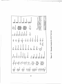
A-3. Schematic Symbols for SCAT Net Lists ..................... 54
A-4. Additional Schematic Symbols . ........................... 55
A-5. Types of Switching Devices .............................. 57
A-6. Schematic of the Example Circuit .......................... 65
A-7. Net List Entry Screen .................................. 66
A-8. Main Menu . ....................................... 66
A-9. IC Message ......................................... 67
A-10. Sneak Input Data Menu ................................ 67
A-11. Reverse Current Path 1 ................................. 68
A-12. Path 1 Highlighted on Schematic .......................... 68
A-13. Reverse Current Path 2 ................................ 69
A-14. Path 2 Highlighted on Schematic .......................... 69
A-15. Power Source Menu ........ ......................... 70
A-16. Ground List Menu . ................................... 70
A-17. Circuit Type Menu ..................................... 71
A-18. Design Parameter Summary . ............................ 71
A-19. DesignConcern Type Menu ............................. 72
A-20. Switch/Rdlay Model Menu .............................. 72
A-21. Switch Configuration Menu . ............................ 73
A-22. Main Menu Listing M-B-B Switches . ...................... 73
A-23. Reverse Current Path 4 ................................ 74
A-24. Path Marked for Deletion . ............................. 74
A-25. Regenerated Reverse Current Path 1 ........................ 75
A-26. Deleted Paths Screen . ................................ 75
A-27. Power-to-Power Tie Warning Message ..................... 76
iv
Figure A-28. Power-to-Power Tie Highlighted on Schematic
Figure A-29. SCAT Program Flow .................................
................
76
77
LIST OF TABLES
Table
Table
Table
Table
Table
Table
Table
Table
Table
2-1.
2-2.
2-3.
2-4.
2-5.
3-1.
4-1.
A-1.
A-2.
1988 Survey of PC-Based Schematic Capture Products .............
Organizations Contacted for the SCA Survey ....................
SCA Survey Summary ...................................
Equipment Concerns of Reliability Analyses ...................
SCA Interfaces with Reliability Analyses ......................
Test Results .........................................
SCA Report Checklist ..................................
SCAT Programs, Knowledge Bases and Databases ................
SCAT Data Files ......................................
LIST OF ACRONYMS
CAD
CAE
CDR
DCA
DID
EDIF
EIA
FCA
FMEA
FSCA
FSED
I/O
PA
PC
SCA
SCAT
SOW
Computer aided design
Computer aided engineering
Critical Design Review
Design Concern Analysis
Data Items Description
Electronic Data Interchange Format
Electronic industries Association
Functional Configuration Audit
Failure Modes and Effects Analysis
Functional SCA
Full Scale Engineering Development
Input/output
Program Authority
Personal computer
Sneak circuit analysis
SCA Tool
Statement of Work
v
9
11
12
14
15
31
42
49
50
EXECUTIVE SUMMARY
This report documents the results of a two year study to make sneak circuit analysis (SCA)
more effective by simplifying the procedure and integrating it into the design process.
This effort entailed (1) the conduct of a literature search and an SCA user survey to
ascertain current methodologies and techniques associated with SCA and its support of
other reliability analyses, (2) development of a simplified, manual procedure which provides
design rules for avoiding sneak paths and guidelines for identifying common types of sneak
conditions, and (3) development of an automated version of the procedure integrated with a
popular, computer-aided design (CAD) tool.
The literature search identified two comprehensive, non-proprietary sources for SCA clue
lists. In all, six clue lists were evaluated, with clues falling into one of two broad
categories:
-
Those applicable to specific topological patterns in switching circuits and used for
identifying sneak paths.
-
Those applicable to specific circuit devices or functions and used for identifying
design concerns and to a lesser extent sneak paths.
The most significant problems associated with the clue lists are their lack of structure to
facilitate culling inapplicable clues, inclusion of subjective areas in what should be an
objective analysis, and inclusion of topics better handled by other analyses.
In the user survey, 42 potential SCA users were contacted, and seven provided useful
information by responding to a survey questionnaire. The findings indicated network trees
are required for a comprehensive search for sneak paths. However, these trees are difficult
to implement in that they require significant data processing (performed by proprietary
software) for (1) generating a circuit connectivity list (net list) defining the entire system,
(2) filtering redundant or non-essential information from the list, and (3) partitioning the
net list into segments suitable for manual application of the clues. This study concentrated
on developing guidelines for identifying sneak circuits that are independent of circuit
topology, thereby eliminating the need to generate network trees.
Additional findings of the user survey were:
-
The current, prevalent procedure for SCA consists of automated formatting and
partitioning of schematic and net list data, semi-automatic generation of network
trees, and manual application of sneak clues and design concerns.
-
Efforts are underway for reducing, the requisite computer resources
mainframe to a workstatign.------
-
Functional networks (e.g., block diagrams) are rarely analyzed.
vi
from a
iL
-
The most Pievalfnt ty6es of arialysds for Which SCA databases .and results are
shared are FMEA and fault tree analysis.
The last point was supported by a survey of related analyses conducted as part of this
study. The analyses survey also found that fault tolerance design compliance analysis has
an important interface with SCA because the criticality of the functions that make SCA
necessary also require fault tolerance, and the latter must address the absence of design
hazards (such as sneak circuits) that can defeat its purpose.
The manual SCA procedure was documented in a separate report entitled Sneak Circuit
Analysis for the Common Man (report number RADC-TR-89-223).
The procedure is
intended for the design engineer or electronics reliability analyst without prior SCA
experience. The report includes a simplified set of sneak related design concern clues that
can be applied to circuitry at the- assembly, or subsystem levels by personnel who
understand the operation of the circuitry and the devices comprising it. Supplementary
explanations, problem illustrations, and recommended solutions are also provided. The
clues address areas such as improper switching elements in power return lines, timing
problems associated with relay circuits, and problems associated with application and
removal of power to digital circuitry. The report can also serve as a guidebook for
familiarizing engineers with the techniques for designing circuits free of commonly
encountered sneak problems.
An SCA tool (SCAT) was developed to automate the manual procedure and to extend it to
include automatic identification of sneak paths in switching circuits. An example of a
sneak path identified by SCAT is shown in Figure 1. The highlighted path begins at the
point labeled SRC, passes through relay K1 (switch contact), switch S2, and back through
relay K1 (coil) before terminating at ground. The sneak results in an oscillatory condition
that alternately energizes and de-energizes the relay. SCAT designates the path by listing
the affected devices in their order of appearance along the path (i.e., K1-S, S2, Kl-C).
The SCAT program requires only a few minutes to run, the actual time being dependent
upon the size of the circuit analyzed. As in the manual procedure, the SCAT user must
understand the operation of the circuit under analysis in order to evaluate identified sneak
paths and to respond to prompts addressing design concerns. The program, consisting of
an expert system knowledge base augmented by external code, runs on IBM-PC/XT, /AT
or 80386 class microcomputer running under MS-DOS. The user must provide the M.A
(Teknowledge, Inc.) expert system inference engine software environment to run the SCAT
program. Input to SCAT consists of net lists generated by a popular, commercially
available schematic capture program (OrCAD/SDT 11) that must also be provided by the
user.
This report concludes with an evaluation of current SCA control and
and in this regard recommends revision of two existing DIDs. The
requirements tur performing follow-up SCA effectiveness and
Examples of the revised DIDs are provided in the appendices to this
user's manual for the SCAT program.
vii
monitoring procedures
revisions address data
thoroughness studies.
report as is a detailed
0*-
L4
00
viii
Chapter 1
INTRODUCTION
This report documents the results of a two year study to make sneak circuit analysis (SCA)
more effective by simplifying the procedure and integrating it into the design process.
Sneak circuit analysis is defined in MIL-STD-785B, the military standard for reliability
programs, as a procedure "to identify latent paths which cause occurrence of unwanted
functions or inhibit desired functions, assuming all components are functioning properly".
The procedure is particularly applicable to military systems because of the potential for
identifying and correcting design weaknesses that could lead to catastrophic failure'.
However, the procedure is not as widely used as it should be primarily because:
-
Its conduct is expensive, being highly labor intensive and often requiring an
independent contractor having specialized tools and trained analysts.
-
The effort requires complete documentation and therefore is usually performed
late in the design cycle or early in the production phase when changes are
more costly and difficult to implement.
-
The separation of the organization performing the analysis from the
organization responsible for the design often leads to problems being
incorrectly identified or to identified problems not being corrected.
The objective of this study was to overcome these deficiencies by simplifying the
procedure and integrating it with other analyses performed during the design phase. To
this end, we (1) conducted a literature search and a SCA user survey to ascertain current
methodologies and techniques associated with SCA and its support of other reliability
analyses, (2) developed a simplified, manual procedure which provides design rules for
avoiding sneak paths and guidelines for identifying common types of sneak conditions, and
(3) developed an automated version of the procedure integrated with a popular computeraided design (CAD) tool. The procedures are intended for the reliability analyst or design
engineer without prior SCA experience.
The results of these three tasks are described in the remainder of this report. Chapter
Background and Interim Results, summarizes conventional SCA procedures and briefly
discusses objectives and accomplishments during the first half of this contract including
development of a new, manual procedure. Chapter 3, Automated SCA, describes the
development and operation of the new, automated procedure, its integration with existing
design tools, and its relevance to other reliability analyses. Chapter 4, SCA Control and
',
This report does not address a related procedure for software, Sneak Software
Analysis.
Monitoring, presents recommendations for data collection to assist in managing and
evaluating contractual SCA efforts.
Chapter 5, Recommendations for Further Study,
addresses areas that were beyond the scope and resources of the current study. A user's
manual for the automated SCA tool (SCAT) and proposed data items for control and
monitoring of.SCA appear in appendices to this volume of the report
The SCAT software, consisting of an expert system knowledge base augmented by
programs coded in C, is documented in Volume II of this report. The documentation
consists of printouts of the C source code and knowledge base, both of which include
extensive comments, and descriptions of the program flow and data structures utilized. For
ease of reference, each major subprogram and knowledge base segment is listed in the
table of contents for Volume II.
This study was a two year effort commencing on September, 1987. SoHaR Incorporated,
the prime contractor for this study, was respoffsible for developing the manual and
automated procedures described in the report and for writing the C-code and M.1
knowledge bases required for SCAT. Fail-Safe Technology Corporation was the principal
contributor for development of the control and monitoring procedures. An analysis and
evaluation of candidate expert systems for the automated procedure was performed by Dr.
Lawrence Press, a consultant to SoHaR. Overall technical direction was provided Mr.
Bruce Dudley, RADC/RBER.
2
Chapter 2
BACKGROUND
SCA has been in use for over 20 years, the first major computer aided version having been
developed for the NASA Apollo program in 1967 by the Boeing Company [CLAR76].
The original application of SCA was for switching and relay networks for engagement and
disengagement of control functions such as those used in automatic pilots and in missile
and spacecraft systems. These applications are referred to as "electro-mechanical circuits"
in MIL-STD-785B, where SCA is specified as Task 205; in this report the shorter terms
"switching circuits" or "relay circuits" are used (the two expressions are considered
synonymous). The change in terminology also recognizes that relays are no longer
exclusively electro-mechanical devices.
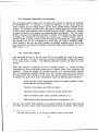
2.1 Conventional Techniques
The techniques for identifying topological sneak paths in switching or relay circuits are
applicable to all functions that evaluate Boolean variables exclusively, Such circuits may
be comprised of manual or sensor-operated switches, electro-mechanical or solid state
relays, or combinatorial digital logic circuits (but not sequential or memory-dependent
ones). The logic circuits are modeled by their switching circuit (switch and diode)
equivalents. Functional paths such as those between relay coil and contact and between
poles of a multiple pole switch are also modeled.
The primary objectives of SCA in switching circuit applications are to uncover sneak
problems in four principal areas:
Sneak Paths
Unintended electrical paths within a circuit and its external
interfaces.
Sneak Timing
Unexpected interruption or enabling of a signal due to switch
circuit timing problems.
Sneak Indications
Undesired activation or de-activation of an indicator.
Sneak Labels
Incorrect or ambiguous labelling of a switch.
Because it was found that frequently encountered causes of sneak circuits were associated
with distinct topological patterns on circuit diagrams, the identification of these patterns and
the recording of specific circuit attributes applicable to each pattern were considered
efficient means of using past experience to guide a current analysis. This conventional
approach led to the development of semi-automated methods of isolating the topological
3
patterns in relay circuits and to the generation of clue lists applicable to each type of
topological pattern. The most significant of these patterns are the "Y" (power dome),
inverted "Y" (ground dome), and "H" (cross-tie) where in each case the pattern depicts
power flow from source(s) to ground(s). Additional patterns for analog and digital signal
flow have also been developed.
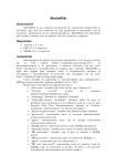
A simple example of the conventional approach is demonstrated with the help of Figure 21. The functional circuit depicted in part A of the figure is intended to prevent routine
opening of a cargo door unless the aircraft is on the ground. For this reason, the primary
switch that controls the door opening is energized through the Gear Down contactor. A
secondary switch permits emergency operation of the door when the gear is not down.
Due to a sneak path, closure of the emergency door switch when the primary switch is
closed will inadvertently lower the landing gear.
In the conventional SCA approach, accurate, production-level drawings of the circuitry are
The circuit
required to insure all circuit paths are considered by the analysis.
interconnection data are partitioned for constructing "network trees" to filter non-relevant
schematic data and generate a visually simplified presentation of the circuit. Several
versions of the trees may be required to analyze circuit switching configurations
corresponding to a timed sequence of system states.
The topology of each network tree is analyzed for the appearance of the key patterns; for
the cargo door example, an "H" pattern is recognized. The H pattern is more apparent
from the network tree drawn in part B of Figure 2-1 than from the circuit schematic drawn
in part A. The tree is constructed by tracing all possible paths from power to ground
assuming all switches are closed, and is drawn such that power flows from top to bottom.
Appropriate topologically oriented sneak clues are then applied to the pattern, and if an
answer is affirmative, the sneak path is identified. In this example, it can be prevented by
insertion of a diode in series with the primary switch as shown in part C of the figure.
In recent years, the scope of SCA has been expanded to include clues for identification of
design concerns in analog and digital circuitry. Some design concerns imply the existence
of a sneak path or sneak timing while others are completely unrelated to sneak conditions
and merely indicate a violation of good design practice. Design concern clues aid the
analyst to identify potential problems affecting specific devices or circuit functions.
4
EMERGENCY
DOOR OPEN
+
DOOR OPEN
GEAR DOWN
0-
....
. GEAR I.............
-0
()
ORIGINAL CIRCUIT
DDOOR
DOWN
GEAR
NORMAL
OPEN
OPEN
\DOOR
EMERGENCY
DOOR OPEN
(b) NETWORK TREE
GEAR
DOWNO
EMERGENCY
DOOROPE
DOOR OPEN
o
+
GEAR DOWN
0 --
F
NORMAL
DOR OPEN
I
o(C)
REVISED CIRCUIT
Figure 2-1. Example of a Sneak Circuit
5
GEAR
SCA is a highly labor intensive task requiring significant computer resources for support.
For this reason, it is typically applied only to mission or safety critical areas of a system.
The circuit interconnection data for these sub-systems can be quite complex, with
documentation spread over many drawihgs (e.g., circuit card schematics, inter-card wiring
lists, and subsystem cabling diagrams). Automated techniques for capturing the circuitry
and generating network tree interconnection data have been developed and have proved to
be indispensable for efficient, accurate and thorough analysis of large systems. The
software for performing the circuit data capture and tree generation is considered highly
proprietary by those contractors that have developed an SCA capability. Furthermore, a
team of specially trained analysts are required to apply sneak clue lists (many of the lists
are considered proprietary as well) to the hundreds of network trees that are typically
generated. For these reasons, performance of the analysis is limited to SCA contractors in
all but the simplest of cases.
2.2 Interim Results
In order to build a foundation for the development of a simplified integrated version of
SCA, a data collection task was performed. The task consisted of three major activities:
1.
2.
3.
A literature search
A user survey
A survey of related analysis techniques
The collected data was evaluated in the specific areas of clue lists, SCA techniques and
related analyses. The data and the evaluation results are summarized in the following
sections.
2.2.1 Literature Search and Analysis
The literature search identified existing, available information related to sneak analysis
techniques, methods of execution, and problem areas. Sources included the DTIC, NTIC
and UCLA library data bases. The search also identified design tools that could be
integrated with SCA to enable a design engineer to perform the analysis as an ongoing part
of the design process. The tools investigated were (1) computer aided design products
presently being used for electronic equipment design and (2) expert system building tools
for test and analysis applications. A listing of significant references appears in the
bibliography of this report.
The performance of SCA is centered on the use of clue lists serving as checks or guides
for the analysis. Two broad categories of clues can be distinguished:
Clues applicable to specific topological patterns in switching circuits and used
for identifying sneak conditions.
6
1.
Clues applicable to specific circuit devices~or functions and used for identifying
design concerns and to a lesser extent sneakconditions.
Two of the references identified by the literature search are comprehensive, non-proprietary
sources for SCA clues. This is significant since sneak clue lists have traditionally been
considered proprietary and were not published. Reference [NP3634] includes 106 clues in
three major categories: (1) tree topograph, (2) piece-part and circuit configuration, and (3)
design concerns. Clues in the latter category are accompanied by explanations to assist
less experienced analysts. Reference [MS1543B] includes 128 clues also in three major
categories: (1) functional, (2) design oriented, and (3) design concern. The design
oriented clues are written so as to enable identification of sneak conditions (i.e., paths,
timing, indications and labels) without reference to network tree topographs.
An evaluation of these clue lists and four others obtained during the course of this study
(covering approximately 150 unique clues) revealed that while ,the clue lists provide a
valuable guide for relatively inexperienced personnel, they are time consuming and tiring to
use because they:
-
Lack structure by not being arranged in a manner that permits skipping a
number of subordinated items when a negative (no sneak circuit possible)
finding is reached for a top level clue.
-
Mix areas in which subjective analysis is required (such as the appropriateness
of labels) with areas in which clear decisions are possible (such as the
possibility of unwanted current flow).
-
Include questions that are clearly the responsibility of the design engineer (such
as the compatibility of loads with power sources).
Information on problems related to the performance of SCA has been amply reported in the
literature ([BALD87], [BURA82]) and are evident in final reports of specific SCA
applications.
The major problem areas arise from performing SCA too late in the
development cycle by a SCA specialty team too removed from the design effort and from
the diversity of interests of the performing organization with the organization responsible
for the design. Thus, the results of a thorough analysis are typically contested by the
design organization either because the sneak circuits identified in fact do not pose a
problem or because their degree of significance does not justify the cost of their removal.
The solution is to simplify the analysis such that it can be applied in the early phases of
the design effort either by design personnel or under their guidance.
The purpose of the CAD survey was to identify methods by which an automated SCA tool
could easily interface with a schematic capture tool and to select a specific schematic
capture product for implementing this interface. These products accommodate on-screen
graphical and textual editing of circuit schematics and include provisions for outputting
circuit interconnection data in various formats for use by other products such as those for
circuit board trace routing and circuit or logic analysis. Methods of integration that were
considered included feedback of SCA results into the on-screen schematic, incorporation of
7
SCA clues into the design error checking facilities found in many of the products, and use
of the circuit interconnection data (the schematic net list) as an input for the SCA tool.
A voluminous amount of information on CAD techniques is available in the literature. In
order -to focus on the study objectives, the scope of the search was limited to schematic
capture products capable of running on a personal computer. The personal computer (e.g.,
the IBM-PC family of desktop microcomputers) is becoming prevalent in engineering
organizations as its computing performance and memory capacity have increased, and a
growing number of circuit design and analysis applications are available that take advantage
of these gains. PC-based schematic capture and circuit analysis products provide a costeffective means for interfacing SCA with design data particularly during the early phases of
a development effort.
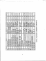
The extent of the investigation of schematic capture products performed during this study is
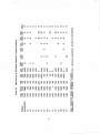
shown in Table 2-1. Data for the table were compiled in August of 1988. In addition to
basic product information (year product was introduced, number of sales, and cost), the
table also includes the following technical characteristics:
Library size
The number of unique, graphical component symbols available
for schematic editing.
Library type
Type of components covered; analog (A), digital (D), or both.
EDIF Net List
Compatibility with the EDIF industry data formatting standard.
Layout Tool
Product can also perform component layout.
Analysis Tool
Product can also perform circuit or logic analysis.
External Annotation
Capability for external programs to modify the schematic.
Hierarchical Schematics
Capability for representing schematic data hierarchically in
addition to a flat, multi-page format.
Rule Checking
Provisions for identifying violation of design rules.
Video
Compatible with high resolution color monitors (C), high
resolution monochrome monitors (M) or both (B).
Based upon this investigation, the possibility of displaying SCA results within the on-screen
schematic was considered impractical because none of the products surveyed provided a
means for graphically highlighting a specific component or path, and except for one
produce "hooks" were not provided in their software for a user to do so. An additional
objection for attempting this involves the MS-DOS operating system for the PC. The user
2Product
"B" in Table 2-1 provides an open database and ASCII file formats.
8
0
x
x-
X
0
X X
0
C)f
0
00l
-1
-4
5
-4
Z<
would have to manually perform the time consuming steps of exiting and re-entering the
programs each time he desired to view the SCA results on the schematic.
The possibility of adding sneak circuit checklists to CAD schematic capture products was
also investigated. Most schematic capture products include a rule checking capability for
identifying certain types of drawing errors. The rule checking code, however, is in a
closed format that cannot be modified without detailed knowledge of the entire schematic
capture program. Alternatively, the net list output of the captured schematic can be used
as an input to an external program for automating the SCA checklists. This latter approach
is the one chosen for SCAT and is described later in this report.
Of the products surveyed, OrCAD/SDT was the one selected for integration with the
automated SCA tool because of its compatibility with MS-DOS, low cost, wide popularity,
and provisions for generating net lists in an industry standard format (specifically,
Electronic Data Interchange Format, or EDIF).
Earlier work by SoHaR demonstrated an advantage for using expert system technology to
aid the application of SCA clues. This technology is central to the automated version of
SCA being developed under this study. A survey of PC-based expert system shells was
undertaken to facilitate the selection of an optimum tool for automating the analysis. In
addition, eleven expert system shells were evaluated in terms of execution efficiency,
development efficiency, user interface, developer interface, external interface, inference
process, knowledge representation, and developing company policy regarding the use of the
shell as part of another product.
2.2.2 User Survey
A survey of vendors of SCA and of those who require or specify its performance was
undertaken to determine the current state of the art and practice of the analysis technique.
Approximately 42 organizations were identified as prospective SCA users and contacted
regarding our request for completing a survey questionnaire. The organizations are listed
in Table 2-2. As indicated by the first column in the table, these were either prime
contractors or government organizations. As indicated by the last column in the table,
most declined to participate, either because they in fact did not use or perform SCA (half
of the prime contractors contacted were SCA users) or did not wish to divulge the
requested information. Seven did respond, and a summary of the data they provided
appears in Table 2-3.
10
000*
o~~
o
0']
0ooooooo
~
4C )
0
>.zzzzz
>
cz-i~(
zO4zEz)z z
0 1 4 0oo
)c0
3
o
aw
.
4o ) 0C 4
20
0
o
0
~0
£C'4
eoo 04).. C~d
d' m m c
Cc
:
OO>
mC04
0
0
0
oO C C C C
0 00
.x
'40
'ZCC z
>.
'0
z
~ coa'~o~o
4)~ot~
0
CO
~
.eu
0
z 'z
Z 0Z
oC
o o
o
0
00
k
0 V
u
0.-4.-0
C
O~JOA
4 )
O
)
004'~
OC
00
04)
Li
44)
.
)-s
0 Ca
4
C)
J
-4
~
C
Q
0o s
t0a4)0W'.4
f
4
z
0jJ
0
0
W).)
4
04C))m
0)4) 4
4
0 10 c
z
0~~0
ca0
cak~
ca 0co0m0U4)C4
C
4]''
0 c4
4 4c 4ce 0
0' 'V ' 4
v44
o
O
,j
4
'c 0000
04
0
.
o
0
'4
Q
4)))0
4 o
m' 0. a.
m.
at
:'
C)C
u
"00
44
c
o
o
U)fE-(
4)
.
v-.-0
- -4
d' a)O4'Ol3: 3:
4044
m. a.
a.
m. a0.
4)
o
z
0. a. 0..
4) 0
T u
C C C
4)CC
LiJM
>
LO)4).
0
C
~
.
*
o
C
C4)0M
0 m.
11
.
C>
tu>
U4CC
C
Q
E'O
WOE
)~0
CY04)>)4)tJ
OO
4 )
e
Z
mZ
W00
0
0
z
Em
~
'4k
0r4~
0A0
M
o
'ZZZZZZ
4 )
.M
>.
>. z
EC'~.
ooo)ooo
)a,4 0C
a
4
C C
00
4J
0
w 0V
04
4
O
E
k0
0004
U44) Q
v. =. v a a. a. a. a. a.aVa
4)
4OCO
0
CC
UY
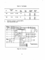
Table 2-3. SCA Survey Summary
Area
Procedure:
Circuit
Partitioning
Number of
Respondents
Comments
4
Three perform it manually. One has a fully automated system.
Network Tree
Generation
3
Two have manual and computer-aided procedures. One has a
fully automated procedure.
Automation
Environment
2
One indicated the need for a minicomputer or mainframe. Both
indicated that SCA work stations are under development.
Schematics
4
All use manual and computer-aided procedures.
Net Lists
3
All use manual and computer-aided procedures.
Functional Nets
3
All have manual procedures. One has a computer-aided procedure.
Timing Data
3
All have manual procedures. Two have a computer-aided
procedure.
ClIe Tv :
Sneak Paths
4
All have manual procedures addressing analog and digital circuits.
One has a computer-aided procedure.
Sneak Timing
4
All have manual procedures addressing analog and digital circuits.
Two have a computer-aided procedure.
Design Concerns
4
All have manual procedures addressing analog and digital circuits.
Two have a computer-aided procedure.
Design Integration:
FMECA
5
Data Entry:
Tolerance
4
Fault Tree
5
Power & Load
2
Grounding
2
Safety
3
Application Phase:
5
Respondents indicated the use of SCA results or tools
(i.e., trees) to aid the performance of these analyses.
One respondent has applied SCA prior to Full Scale Engineering
Development (FSED). All have applied SCA during FSED.
12
The summary table indicates that:
-
The current, prevalent procedure for SCA consists of automated formatting
and partitioning of schematic and net list data, semi-automatic generation of
network trees, and manual application of sneak clues and design concerns.
-
Efforts are underway for reducing the requisite computer resources from a
mainframe to a workstation.
-
Functional networks (block diagrams) are rarely analyzed.
-
The most prevalent types of analyses for which SCA databases and results
are shared are FMEA and fault tree analysis.
Conventional SCA techniques are based upon the generation and utilization of network
trees. Trees aid the analysis by segmenting the circuitry into small topologically related
units, omitting extraneous detail and drawn in a logically consistent manner (power flow
from top to bottom, signal flow from left to right). The trees are carefully annotated to
facilitate cross-referencing with each other and with the analysis input data (schematics,
wire lists, parts lists, etc.). Proposals have been made for utilizing the network tree
database to support other analyses such as FMEA, fault tree analysis and power loading
analysis that require evaluation of circuit topology [CLAR80], [NP3634], [RANK70].
Network trees are difficult to implement because of the complex processing required for
their generation. Proprietary, automated algorithms are used for partitioning the circuitry
into segments on which the trees are based. This approach may be the only one feasible
for thoroughly analyzing an entire set of schematics associated with medium to large
systems. These drawings are usually not available until late in the development cycle (i.e.,
toward the end of Full Scale Engineering Development (FSED) and beyond).
The analysis procedure can be simplified by
topology and therefore can be applied without
is particularly applicable to the early phases of
for generating trees are not available and is
procedures described later in this report.
considering clues that are independent of
the need for network trees. This approach
a design when detailed circuit data required
the basis for the manual and automated
2.2.3 Related Analyses
As part of the data collection task, information was gathered on reliability analysis
techniques that are prospective candidates for integration with SCA. The more widely used
of these analyses are FMEA, fault tree analysis, worst case analysis and preliminary hazard
analysis. It was observed that activities currently being conducted under the heading of
sneak circuit analysis interface with, and partially duplicate, the above analyses and other
reliability, safety, and design tasks. The nature of the interface, the data and techniques
that may be common, and the allocation of currently duplicated or undefined
responsibilities were evaluated during this study.
13
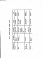
In this connection, it is convenient to divide the reliability centered activities into those that
relate to operational (non-failed) equipment, those that relate to failed equipment, and those
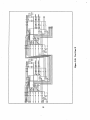
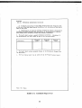
that relate to safety. This division is shown in Table 2-4. A problem in the integration of
sneak analysis with all of these is that on a given project there is no certainty that any of
the other analyses are being conducted.
Table 2-4. Equipment Concerns of Reliability Analyses
OPERATION
FAILURE
SAFETY
Worst Case Analysis
Failure Modes & Effects Analysis
Preliminary Hazard Analysis
Component Tolerance Analysis
Fault Tree Analysis
System Hazard Analysis
Fault Tolerance Analysis
Common Cause Failure Analysis
Operations Hazard Analysis
Sensitivity Analysis
Fault Hazard Analysis
Power & Load Analysis
Accident Analysis
Grounding Analysis
With respect to FMEA, probably the most widely invoked task of those shown in Table 24, there is much latitude in the level of detail that is required to be covered, and therefore
uncertainty about the usefulness of close integration with SCA.
A summary description of interfaces between SCA and related analyses is presented in
Table 2-5. The greatest potential for duplication (and therefore also for cost reduction)
exists between SCA and the operational group of analyses. Worst case and sensitivity
analyses cover many of the areas that are included in the design concern analysis part of
SCA. Worst case analysis considers system performance when component tolerances and
environmental conditions are at their specified extreme limits. Sensitivity analysis evaluates
the degree to which system performance is affected by small variations in the values of the
system components.
Where compliance with fault tolerance design criteria must be analyzed (MIL-STD-785B,
par. 50.2.4.1), this also has an important interface because the criticality of the functions
that makes SCA necessary will in most cases also require fault tolerance, and the latter
must address the absence of design factors (such as sneak circuits) that can defeat its
purpose. Single point failure analysis, an important part of fault tolerance analysis, has
significant interfaces with sneak circuit analysis.
Grounding analysis, which is really a design rather than reliability technique, covers one of
the most critical parts of SCA, particularly for relay circuits, and coordination of the
activities presents an opportunity for substantial cost savings. The analysis addresses the
14
0~
0 (n
0
0~
LU.
0.
;>
a
04
0
o-
-o40
z
C.)
0
75
0:
00
000)C.
0*-
LWC
co) "0
u.
U~4.
Z
0.0
Q
-
Q
~>
0
0
0
~
~
ot ~
00
Lt
I
F-
rz~2.
2
al
W
Ll.
M
0
.5
possibility of current flow between ground nodes, a condition often associated with sneak
circuits. Power and load analysis, another design technique, eyaluates open circuit voltages
and short circuit currents on lines controlling hazardous functions.
With regard to the failed equipment analyses, the most important interfaces exist with fault
tree and failure modes and effects analysis. Fault tree analysis is a "top-down", deductive
procedure for identifying causes of system failures. The analysis utilizes diagrams referred
to as fault trees for depicting the dependency of higher level failure events on lower level
events. Common cause failure analysis is a similar top-down procedure that identifies
single failure events caused by the occurrence of multiple events. The analyses, where
they are being conducted, can be used to identify the functions and components to be
subjected to SCA. By narrowing the scope of the latter, substantial cost savings are
possible.
Failure modes and effects analysis (FMEA) shares important techniques with sneak circuit
analysis, including the use of network trees. FMEA is a "bottom-up" procedure for
inferring the higher level effects of postulated, lower level failures. The effects may be
used as a baseline for an extended SCA where the analysis is required to identify sneak
circuits in the presence of one or more faults. Here, a sneak circuit can compound the
effects and increase the criticality level. Also, some of the effects of failures may be
duplicated by improper or unintended operation of non-failed equipment. Thus sharing of
data may be beneficial. Where fault tree analysis is not being conducted, the components
associated with catastrophic and major failures in FMEA can be used as a candidate list
for SCA. It is important to realize that FMEA is frequently a basis for the design of
built-in test and operational test equipment and for maintenance and logistics activities. It
is thus a primary task under MIL-STD-785B that should not be made dependent on the
results of SCA.
Safety analyses include the preliminary hazard analysis for evaluating potential hazards
early in the system design, system hazard analysis for identifying hazards later during
system development, operation hazard analysis addressing hazards associated with fielded
equipment, fault hazard analysis for identifying potential hazards caused by component
failures, and accident analysis. The sharing of data and techniques with safety related
activities may be deliberately restricted in order to keep safety activities for highly critical
equipment independent of reliability and design. However, in other cases information
sharing may be permissible and should then be encouraged in order to contain costs.
2.3 A Simplified Manual Procedure
The manual SCA procedure developed during this study is a simplified version of the
conventional procedure. It is intended for use by the design engineer or reliability analyst
as a means for both avoiding designs likely to contain sneak paths and for identifying most
instances where sneak paths exist. It is not intended as a substitute for the conventional
procedure applied to a fully developed system but instead serves as a simplified method for
minimizing the number occurrences of sneak conditions early in the design effort.
16
L
The procedure was developed by compiling sneak clues from several sources (see section
2.2.1), selecting clues most relevant to identifying sneak problems, and generating a concise
yet thorough guide for their application. The guidelines resulting from this effort are
categorized as follows:
1.
Design rules for an engineer to follow early during development to avoid
designing circuits prone to sneak conditions.
2.
Functional guidelines for an engineer or reliability analyst to identify sneak
crnditions appearing in power distribution circuits, power and signal timing,
and status indicator circuits.
3.
Device guidelines for an engineer or reliability analyst to identify sneak
conditions caused by circuit devices including relays, transistors, and linear
and digital integrated circuits.
Each design rule and guideline contains a brief statement of the problem being identified, a
recommended solution, a supplementary paragraph describing the problem in greater detail,
and an illustration of the problem and solution. The guidelines also include a descriptor
for categorizing the targeted circuitry.
The design rules are the most cost-effective of the three items for addressing sneak
problems during design and for this reason are emphasized by the procedure. It is far
easier and less costly to avoid sneak circuits through proper design techniques than to
identify and correct sneak circuits after the design has been completed.
While the design rules are intended for an engineer responsible for circuit design, the
functional and device guidelines are intended for either an engineer or an analyst familiar
with the operation of the circuitry and its constituent devices. The functional guidelines
may be applied before specific circuit device types have been finalized. Their application
requires a diagram depicting power distribution at the assembly (e.g., printed circuit board)
level and identification of analog or digital and high or low current areas of the circuitry.
The device guidelines are applied after circuit devices have been selected for the ,'esign.
The selection need only be generic (e.g., NPN bipolar transistor, low power Schottky TTL
digital counter); specific part numbers are not necessary. For complex systems, application
of the guidelines should be focused on circuitry associated with critical system functions
rather than the entire system. Critical functions may be identified by fault tree analysis or
FMEA.
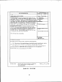
The manual procedure is documented in a report titled Sneak Circuit Analysis for the
Common Man (report number RADC-TR-89-223) generated as a part of this study. An
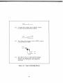
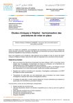
example of a design rule appears in Figure 2-2, and an example of a guideline appears in
Figure 2-3.
17
Rule 1. MULTIPLE POWER SOURCES AND RETURNS
PROBLEM:
Sneak paths Involving multiple power sources and/or multiple
ground returns.
SOLUTION:
Structure circuits so that all current for a given load flows from
one power source to one ground return. Where this is not
possible, Isolate power sources using diodes for DC power or
relays (electromechanical or solid-state) for AC or DC power. Use
Schottky diodes or relays for DC applications requiring very low
voltage drop and power dissipation. Isolate returns by separating
high and low current loads.
PIR
ALT
PFR
PtR
ALT
PWR
PWR
P
2
S11
6tZ
3
S
XI
ALT
PR
PR
S2
KI
SI t
S.3X
X2
OND
'A) RECOMMENOEO
xi
X2
GND
ALT GND
l
GND
X
ALT CNO
(C) DESIGN
SOLU7ION
(0) UNDESIRED
i
GND
2
ALT GN
(0) ALTERNATIVE
SOLUTION
Figure 3. MULTIPLE POWER SOURCES AND RETURNS
Adherence to this rule avoids "Y," "X" and "H" circuit patterns associated with
multiple power sources and sinks (see Chapter 2). This is a general rule to be
followed wherever possible. An example of a network complying with this rule
appears in Figure 3A, and at example of a network violating it appears in part B of
the figure. The violations shown can result in power-to-power or ground-to-ground
ties. Isolation must be provided to avoid the mixing of low current and high current
ground returns. Examples are shown in parts C and D of the figure.
Figure 2-2. Design Rule Example
18
POWER DISTRIBUTION CIRCUITS
TARGET:
Primary and secondary power distribution circuitry comprising power
sources, ground returns, switches, contactors, relays, circuit breakers,
fuses, solid state switches, connectors.
PROBLEM:
Asymmetrical pattern of connections for power distribution and
ground return circuitry.
SOLUTION:
Use the same circuit connection topology for the supply side and
ground side of a load. Use the same connector for symmetrical
power and ground connections.
COMMENT.
Circuit connection symmetry for power and ground distribution implies an
identical number and location of power and ground connections feeding a
load. Asymmetrical connections can cause sneak paths as shown in
Figure 10. In part A of the figure, power connection J3 has no counterpart
on the ground side of load X2. If connections J2 and J3 are open while
the remainder are closed, current can unintentionally flow in the reverse
direction through X2. This problem has been eliminated in part B of the
figure by the inclusion of connection J3-2.
X1
X(2
J4-1
,,3-1
,4-1
J3
FIR
V>
1(3
)n
> f.4-2
X2
Z33-234-2
T-
(A) PROBLEM
(B) SOLUTION
Figure 10. SYMMETRICAL POWER DISTRIBUTION
Figure 2-3. Guideline Example
19
X(3
Chapter 3
AUTOMATED SCA
This chapter describes the development and operation of a simplified, automated SCA
procedure developed during this study. The intent of developing this procedure was to
demonstrate the concept and feasibility of integrating an SCA tool with an automated
design tool to provide a simple yet effective sneak analysis procedure. To this end, the
procedure and the automated SCAT supporting it were constrained to a specific input
domain (i.e., a net list comprising circuit device types from a specified parts library and
formatted in a specified manner) and to a subset of sneak clues (i.e., those associated with
commonly encountered sneak conditions). However, the procedure can readily be extended
to apply to a wider variety of input data and check for a larger number of conditions.
3.1 Overview
SCAT is a microcomputer based expert system for automatically identifying sneak paths
and design concerns by processing circuit net lists generated by a CAD schematic capture
tool. SCAT differs from conventional SCA techniques in that the latter are based upon the
generation (usually automated) and analysis (mostly manual) of network trees to identify
sneak paths. The proposed tool does not require network trees; in fact, it is particularly
applicable to early phases of a design when detailed circuit data required for generating
trees are not available.
The automated procedure provides the design engineer or reliability analyst with a simple
tool for rapidly identifying and correcting sneak circuits and relevant design concerns.
Identification of topological patterns is not required. Sneak paths are automatically
identified for power switching circuitry. Design concerns relevant to sneak circuits are
identified for analog or digital circuits. The procedure focuses the analysis on portions of
the circuitry for which the analyst has design responsibility (or detailed understanding of its
operation), e.g., a circuit card assembly or a subsystem such as power distribution. A
more extensive analysis would require application of a conventional SCA. However, even
in this case, prior use of the proposed procedure would minimize the number of remaining
sneaks and thereby greatly reduce the cost impact and other concerns associated with
correcting problems late in the design phase.
The automated procedure is based in part on the fact that sneak paths involve circuit
branches that can conduct current in either direction depending upon the switching state of
the circuit. SCAT searches for these bidirectional branches rather than perform the more
complex task of searching for specific topological circuit patterns as done by conventional
automated SCA techniques.
The analyst's task is also reduced to evaluating the
significance of specific sneak paths rather than applying "clue lists" to circuit patterns for
identifying the sneak paths.
20
A significant issue that arises in regard to focusing the analysis at any one time to a
portion of the system is the assurance that sneak paths associated with assembly or
subsystem interfaces are not overlooked. This issue is addressed in two Ways. First, the
system compels- the user to identify each interface port of a switching circuit in terms of it
being a power input, ground return, or signal I/O. Interfaces to power and ground are
labeled as such regardless of whether they respectively go to power and ground directly or
through switched or unswitched loads, and they are included within the sneak path search.
Second, the SCAT is intended to identify many (but not necessarily all) sneak conditions
early in the design when interfaces may not yet be completely defined. In this manner,
problems can be corrected early at minimal cost so that at a later development phase a
more conventional SCA can be performed on the entire system, and uncover the few, if
any, remaining problems.
3.2 Description
The automated procedure comprises four major tasks:
1.
2.
3.
4.
Schematic capture/net list generation.
Sneak path analysis.
Functionally oriented design concern analysis.
Device oriented design concern analysis.
These tasks have been computerized utilizing a concurrent engineering environment
comprising a commercial schematic capture product and the expert system based SCAT.
Schematic capture and net list generation are performed by OrCAD/SDT III version 3.21 or
later release. It is available through OrCAD Systems Corp., Hillsboro, Oregon.
The sneak path and design concern analyses are performed by the SCAT expert system,
developed from an M.1 (Teknowledge, Inc.) expert system shell. The shell consists of the
M.1 inference engine and facilities for developing and maintaining the SCAT knowledge
base. M.1 was selected from among eleven, commercially available, MS-DOS based shells
evaluated for the SCAT application. M.l was selected because of its execution speed (the
shell is coded in C rather than LISP which is used by many others), its rich repertory of
syntactical functions (e.g., pattern-matched variables, a facility for rule looping, and a large
number of built-in meta-facts and meta-propositions), and its open knowledge base (the
rules are formatted in ASCII text).
The SCAT knowledge base consists of approximately 265 rules stored in nine data files.
The knowledge base is augmented by approximately 650 lines of C source code
implementing those portions of the analysis requiring intensive processing. These portions
include reading the EDIF net list and performing the sneak path search. The code was
developed on Microsoft's QuickC environment and C 5.0 Optimizing Compiler.
Information needed for maintaining the program, including extensively documented source
code and knowledge base files, appears in Volume II of this report. To maintain an audit
trail, each file is prefaced by a header identifying the date of the last revision, its
originator, and a brief description of it.
21
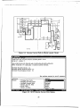
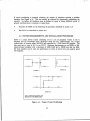
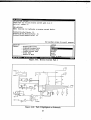
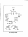
A functional diagram of the system appears in Figure 3-1. Prior to running SCAT, the
user must generate a net list, of the circuit to be analyzed using the OrCAD schematic
capture program. The net list must be saved either on hard disk or floppy disk. SCAT
reads and processes the net list, as directed by the user, to identify sneak paths and design
concerns. Utilizing the user friendly, consultation type interface provided by the SCAT
expert system, the user must specify the name of the net list file and the type of analysis
to be performed (sneak path or design concern). For the sneak path analysis, the user
must confirm that suspicious paths identified by SCAT are in fact sneak circuits (i.e., they
inhibit desired functions or cause undesired outputs).
The expert system provides
assistance for this task. For the design concern analysis, the user must respond to prompts
regarding technical details of the circuit under analysis. Assistance for this is available in
the form of "help" messages. Explanations and possible solutions for identified design
concerns are also available. Operational details, program limitations, and an example of
the procedure are provided by the user's manual in an Appendix A of this report. A
general description of the major tasks involved in the procedure is presented next.
INTERFACE
SCHEMAT IC 4
(OrCAD)
-
CAPTURESYSTEM
.
NE
(EI)(C
0
EXPERT
.1)
ITREADER
CODE)
0PATH
PROCESSOR
(C CODE)
Figure 3-1. Computer Aided System for Sneak Analysis
22
3.2.1 Schematic Capture/Net List Generation
The automated procedure requires that the circuit under analysis be captured and formatted
by GrCAD/SDT III. A schematic is captured by drawing it on the screen using the
various graphics and text editing features and the device symbol libraries provided by the
program. All interfaces involving power and ground, whether direct from external sources
or from external switches/drivers must be labeled using the OrCAD "module port" function
(an option provided by the program for designating signal terminations). This will enable
SCAT to account for all significant interfaces to portions of the system not under analysis.
In addition, the terminals of all internal power sources (e.g., on-board batteries) must be
similarly labeled to address potential sneaks involving power-to-power ties. After capturing
the schematic, the net list is generated and saved using the OrCAD "FlatEDIF" utility.
When invoked by the user, this utility translates the captured schematic into an ASCII text
file conforming to the Electronic Industries Association (EIA) Interim Standard No. 44 for
EDIF version 1 1 0.
3.2.2 Sneak Path Analysis
After generating the net list, the user enters SCAT and specifies the name of the net list
file to be processed. The user is then given the option of performing a sneak path analysis
or the design concern analyses. The following discussion assumes the former has been
selected.
Sneak path analysis is performed on power switching circuitry, i.e., circuits involving
combinations of current interruption devices such as switches, relays, fuses, connectors, and
transistors. During the analysis, all possible non-cyclic (i.e., non-intersecting), directed
paths are automatically identified between every pair of power and power return points in
the circuit (herein after referred to as the source node and sink node) specified by the user.
To facilitate this path search, SCAT automatically models the following types of devices:
-
Switch and relay contact arrangements (single and multiple pole/throw, breakbefore-make and make-before-break).
-
Transistors (both bipolar and MOS) and diodes.
-
Capacitors (under conditions of both AC and DC current flow).
-
Other two-terminal passive devices (resistors, inductors, etc.).
-
Multi-terminal passive devices (transformers, potentiometers, etc.).
The user may override (either globally or for specific devices) the default model assumed
for switch and relay contact timing (break-before-make) and for capacitors (open circuit).
3The
more recent version, 2 0 0, was not available in time for this effort.
23
Connections to integrated circuits are modeled as open circuits since paths are not traced
through these devices.
Following the path search, path sets are identified in which a common branch conducts
current in both directions.
These bidirectional branches are usually indicative of an
undesired reverse current path, the distinguishing feature of a sneak circuit. Each reverse
current path is displayed as a list of schematic reference designators of the devices that
appear along the path, listed in the order of their appearance between the source node and
sink node. Once identified, the user must confirm the validity of the path by considering
operational constraints that may preclude certain switching states assumed by the path in
question. In addition, their potential impact on system operation must be evaluated. The
SCAT expert system provides guidance for these evaluations to the less experienced user.
The guidance is in form of prompts regarding the location of critical loads and the timing
of switches affecting the path.
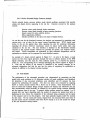
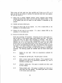
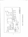
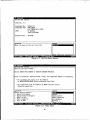
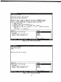
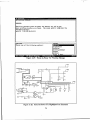
An example of a reverse current path identified by SCAT is shown by the schematic in
Figure 3-2.
The circuit is a simplified version of the infamous Redstone
missile/blockhouse interface that caused premature engine cutoff a few seconds after launch.
The cause was determined to be the sneak path, highlighted on the schematic, between the
launch command and engine cutoff relays that occurred when the ground umbilical
separated a fraction of a second before the separate power umbilical. The net list for this
schematic was processed by SCAT, and the resulting screen corresponding to the reverse
current path is shown in Figure 3-3. The path is identified by the part reference
designators appearing in the schematic.
3.2.3 Functionally Oriented Design Concern Analysis
Functionally oriented design concerns address the following types of sneak conditions:
-
power-to-power ties.
inadvertent load power cutoff by logically AND'd switching devices.
inadvertent load power enabling by logically OR'd switching devices.
improper timing for power enabling and power cutoff.
misleading indications and labels.
More than serving as clues for the analyst, these concerns compose a knowledge base of
rules that are evaluated by SCAT with respect to the specific circuit being analyzed. In
this manner, non-relevant clues are filtered, and wherever possible the user is directed to
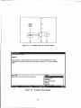
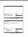
specific areas of the circuit under concern. As an example, consider the power-to-power
tie highlighted in the schematic of Figure 3-4. The circuit is a portion of the FBIlI(A)B
Pivot Pylon Weapon Station Circuitry that underwent a conventional SCA circa 1975
[BOE175]. The power tie was identified by SCAT as shown by the screen in Figure 3-5.
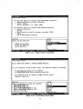
As shown in Figure 3-6, the user is also offered assistance by way of an explanation
message and a possible solution. These aids are directed toward less experienced users.
24
I&
is
0-22
121
02
003
24'P11
Is 0
P
2 P 9
01
P27
3
3O
.~4
4104_
4
JkDe
COIL
M
isCNO$
..
...
I LII
w$$1L
13
PPL IClT ION DISPLAY
[reds.net] src to snk reverse current path I of 9:
pat ref. number: I
[R4-3,P30,P19,P1,PZ,P1B,LP6,*X1-C,*P15o*P6,*PS,*PZ1,*P31,I2I
NOTE: Asterisk (*) indicates a reverse current device.
Deleted Parallel Parts: [I.
AL-
F22 Abor
Scol
Dipay
F0omadMeuRED
Deleted Switch Related Parts: [].
Deleted Miscellaneous Parts: 1].
Use up/down arrows to scroll answers.
QUESTION
Choose:
ANHSWER .
- Display Next Path
- Display Previous Path
previous
analyze
delete
print
return
'L pace to Mark
- Analyze Current Path
- Delete Current Path
-Print Path
- Return to Menu
Figure3-3. SCAT Reverse CurrentPath Display
25
.0
L
I
L0
.1
4;.F
41~~~
L
f
26
,T
PPLICATION DISPLAYWJARNINIG:
Check for possible power-to-power tie between ess_-2fludc and x....8vdC_MaU-fire1
when suitching devices are closed. The sneak path(s) comprises the
following devices:
path(l) = CBZ,P49,P50,H4,P23,P18]
UEST [ON
Choose one of the following options:-
-ANSWER
explanation
solution
Warn ing-jnessage
return
unknown
-Space to Mark
ALT-I
Abr
F2 Scol
Dipa
F1
en
CO-
ED
Figure 3-5. SCAT Power Tie Display
OPPLICATION DISPLAY
A power-to-pouer tie between supplies can result in damage to the
supplies or to the load. This problem can arise if primary and backup
supplies are connected to a common load through a nake-before-breA suitch.
-pgl?
-
For DC power, add diodes to isolate the supplies. Schottky
diodes can be used to minimize the diode voltage drop.
For AC (or as an alternative for DC) use a double-throw relay
or switch having a break-before-make contact arrangement to
select either supply, and provide adequate capacitance at the
load to maintain the supply voltage during suitch-ouer.
-QUESTION
Choose one or the following options:
-ANSWER
-
m099
explanation
solution
warn ing~jiessage
return
unknown
_j [Space to Mark
ALTA
bot
F
Sro.I.ipd
F1 s
m
Mn
Figure 3-6. Explanation and Solution Messages
27
ED
3.2.4 Device Oriented Design Concern Analysis
Device oriented design concerns address sneak related probl6ms associated with specific
analog and digital devices appearing in the net list. Concerns covered by the analysis
include:
-
Reverse current paths through bipolar transistors.
Reverse current paths through op-amp summing junctions.
-
Sneaks caused by noise sensitive devices.
Relay suppression problems.
-
-
Interface problems at the input and output of digital devices.
As was the case for the functional concerns, the analysis was automated by translating each
concern into a set of rules for the expert system knowledge base. SCAT checks each
device in the net list against these rules, querying the user for additional information
regarding the devices whenever conclusions cannot be drawn based solely upon data
contained in the net list. The user interface is identical to the functionally oriented
concerns in that separate display windows are provided for queries, user response menus,
and results. Circuit components are referenced by their schematic designations, and an
explanation or solution can be requested for each identified concern.
An example of a design concern appears in Figure 3-7. As seen in the figure, a sneak
current can flow from signal generator, through the base to collector junction of the NPN
bipolar transistor, and into load X1 when collector power Vcc is removed by opening
switch 51. The corresponding SCAT message identifying this concern appears in Figure 38. Note that the subject of the concern is identified in the warning message by its
schematic designation, and that the user has the option of requesting an explanation or
solution in addition to the original warning message.
3.3 Test Results
The performance of the automated procedure was characterized by processing net lists
seeded with sneak problems to (1) determine whether all sneak conditions were identified,
(2) determine if any non-sneak conditions were identified, and (3) measure the time
required for performing the analysis. The first two items were evaluated by applying
SCAT to various circuits seeded with a known set of sneaks. Time measurements were
only for sneak path searches; design concern analyses are heavily user interactive and any
time measurements would inevitably be affected by the specific design concerns identified
and the response time of the user. In general, design concern screens are updated 1 to 10
seconds after user input, depending upon the number of concerns the system tests prior to
displaying the next screen, the complexity of the schematic being evaluated, and the speed
of the computer used to run the program. User input typically requires under five seconds
for data entry. For the sneak path search, elapsed time was measured from .user entry of
the path search execute command rather than SCAT startup so as to not include the length
of the user interactive startup session.
28
VCC
Signal
GenertorrcX
Figure 3-7. Transistor Reverse Current Sneak
-APLIATIO
DISPLAY
WARNING:
There may be d Sneak path from the base of the transistor(s) (q1i
through the forward biased base-collector junction, to the collector
load.
VEST ION
-ANSWER
AL-
2Srl
ipd
-
M111
explanation
solution
warn ing-message
return
'unknown
LSpace to Mark
Choose one of the following options:
1 Sbr umtdMn
Figure 3-8. Transistor Sneak Display
29
-
ED
Results for three test cases appear in Table 3-1. Case 1 (Figure 3-9) was extracted from
an actual application of avionics switching circuitry in order to test a representative circuit
topography (i.e., realistic ratios of nodes to branches and of series branches to parallel
branches). Cases 2 and 3 (Figures 3-10 and 3-11) were created by, respectively, doubling
and quadrupling Case 1 and adding a bidirectional branch where before there was none.
The net lists corresponding to these cases were analyzed by running SCAT on two
different host computers; an 80286-based and an 80386-based machine, configured without
math co-processors. The resulting path search times ranged from 15 seconds (smallest
circuit, fastest computer) to 85 seconds (largest circuit, slowest computer).
The procedure's effectiveness, as defined by the first two points in the previous paragraph,
was tested by analyzing topologically circuitry having no reverse current paths (Case I) as
well as circuitry with above average numbers of such paths (Case II and III). In all cases,
all seeded reverse current paths were found and no path was mis-identified as being a
reverse current path.
30
Table 3-1. Test Results
Computer
APRAM
Clock
Pert.
Ratio*
Test
Case
Reverse
Paths**
Search
Time
'286
640KB3
10 MHz
11.5
1
II
111
0/0
4/4
8/8
20s
35s
85 S
'386
1MB
16 MHz
18
1
I1
111
0/0
4/4
8/8
15S
25s
50 s
*
**
Performance compared to standard IBM-PC.
Seeded paths/identified paths
Figure 3-9. Test Case 1
31
32
73
let
LlolE
~1If~J
J
It-i~
l
tit
II
33
Chapter 4
CONTROL AND MONITORING OF SCA
A major objective of this study was to develop control and monitoring procedures for
evaluating the effectiveness of an SCA effort. Four areas were investigated in this regard:
1.
Sneak report follow-up procedures. These serve as a procedural control for
assuring that problems identified by sneak circuit analysis are considered (but
not necessarily acted on) by those responsible for the design.
2.
SCA effectiveness -accounting. This reporting area is intended to capture the
impact of sneak analyses on design by measuring the number and
significance of changes that are implemented as a result of SCA.
3.
Thoroughness monitoring. To measure the quality and thoroughness of sneak
circuit procedures, the number of pertinent sneak problems found by other
techniques are compared with the number of problems of equal severity that
are found by SCA.
4.
Cost-effectiveness studies. The resources required to find a problem of a
given severity level by SCA is compared to the resources required to find an
equally severe problem by other techniques.
The investigative approach for these areas was based upon analyzing existing government
and contractor requirements for identification and documentation of sneaks identified as part
of a sneak circuit analysis. The investigation encompassed an evaluation of (1) military
standards, (2) associated Data Items Descriptions (DIDs) and (3) previous studies directed
at sneak circuit analysis. SCA contractors have their individual internal policies and
procedures for performing SCA and tracking resultant identified sneaks. This complicated
the study since contractor procedures could not be obtained. The experiences of the
investigators were utilized to overcome this problem.
4.1 Background
Overall reliability programs for government procurements and for which sneak circuit
analysis may be a part are generally conducted in accordance with MIL-STD-785B.
Reliability program reviews are required by Task 103 of the standard. This task permits
the contractor and the Program Authority (PA) to review overall program status (including
4 The Program Authority is the responsible government representative for specific
program discipline (Program Management, Reliability, System Safety, Engineering, etc.).
34
SCA). The corresponding DID, DI-R-7080, Reliability Status Report, is used to monitor
and evaluate a contractor's progress and accomplishments in conducting the reliability
program for the applicable contract end item(s).
SCA is generally conducted by the reliability or safety organization within a project team
and is performed in accordance with Task 205 of MIL-STD-785B. Sneak analysis activity
is reported via DID DI-R-7083, Sneak Circuit Analysis Report. The DID is invoked for
periodic reporting on the status of all current and previously submitted problem reports
(i.e., Sneak Circuit Report, Design Concern Report, Documentation Error Report, all of
which are in the contractor's own format) and for a final report summarizing the results at
the conclusion of the SCA..
Conventional SCA is based on detailed
data may be available late in program
likely be available late in the Full Scale
from DI-R-7083 may or may not be
milestones.
system drawings and computer programs. These
Demonstration/Validation Phase but would more
Development Phase. Consequently, resultant data
available at significant program decision-making
Sneak report monitoring by the PA depends to a great degree on each contractor's
reporting and tracking process and, to a greater degree, on the contract statement of work
requirements. In general, identified sneaks must be validated and tracked by the contractor
to disposition. Some examples of sneak disposition include no action, system redesign or
follow-on modification. Once verified, sneak reports gain increased visibility. Those with
severe safety or equipment damage impacts are most visible and evoke PA involvement.
4.2 Recommended Procedures
4.2.1 SCA Follow-up
The SOW should require the contractor to track all identified sneaks through to disposition
and to provide resultant data to the PA. In order to maintain proper system baseline
control, the contractor may present the identified sneaks to various review panels and
boards. The PA should attend even the informal reviews in order to monitor progress and
to provide the customer viewpoint when appropriate. The status of all identified sneaks
should be required at key program milestones for the PA to assess overall reliability
program progress. Recommended milestones are Critical Design Review (CDR), Functional
Configuration Audit (FCA) and DD Form 250 sign off.
4.2.2 SCA Effectiveness
This study considers SCA effectiveness to be a measure of the number of identified sneaks
related to the number of resultant design changes implemented. In order to analyze and
measure this effectiveness on one program or across many programs, data must be
available which support such an analysis. It should be noted that relevant SCA data
collection was also recommended in a study completed in 1982 by Boeing Aerospace
35
Company. In part, it stated that "A major element missing from this (Boeing) effort which
could be considered in measuring effectiveness is a method to track the resulting
dispositions for the Sneak Analysis Reports." The report went on to say that only by
collecting relevant data could SCA effectiveness be measured.
In order for the PA to assess SCA effectiveness, all sneaks must be tracked from
identification through resolution and disposition. Collection of triscking data depends on
requirements in the contract Statement of Work (SOW) since there is no DID associated
with a monitor and track task. DI-R-7083 contains general information regarding the SCA
Report content with no specific instructions with regard to items of interest to the PA.
Data collection regarding each identified sneak should logically be performed by the
contractor. These data include elements such as sneak type category, nature of the sneak,
sneak severity category, disposition and manhours and costs to implement design changes.
A weighting factor, based on the sneak severity category, should be applied to weigh the
relative significance of each identified sneak.
4.2.3 SCA Cost-Effectiveness
Relevant data for analyzing cost effectiveness are not generally available. In addition to
SCA data submitted by the contractor, two cost data elements must be added by the PA
before a meaningful analysis is possible. These elements are (1) total contract cost to
perform the SCA, and (2) total program cost. Additional comments such as the size of the
system under acquisition should also be included. Ideally, the information would be
compiled in a relational database to facilitate retrieval for cost-effectiveness analysis. A
relational database is recommended since it provides the required link between significant
data files such as contractor, analysis size and cost.
SCA cost-effectiveness addresses the relationship between the cost of performing SCA,
costs associated with correcting sneak problems, and costs associated with other reliability
analyses such as FMEA, Fault Tree, Worst Case, Finite State Machine (e.g., analyses
utilizing Markov models or Petri net diagrams) which seek to identify deficiencies prior to
integration and test. Cost data for these other analyses should be provided by the PA for
inclusion in a database. The dat -re used to perform the following analyses:
1.
Compare the cost of the SCA with the cost of removing the sneak circuit by
other means.
2.
Compare the cost of the SCA with the cost of the failure that would occur if
the sneak circuit was not found.
4.2.4 SCA Thoroughness
SCA thoroughness is a measure of the type and quantity of sneaks identified as a result of
analyses other than SCA. This measure is appropriate when other analyses are performed
36
on a system whether or not a SCA is performed. Other analyses might include Failure
Mode, Effects Analysis, Fault Tree Analysis, Common Cause Failure Analysis, Sensitivity
Analysis, Worst Case Analysis, Power and Load Analysis, Grounding Analysis, Finite State
Machine Analysis, Preliminary Hazard Analysis, Desk Checking and Peer Code Review.
To measure SCA thoroughness in this context, the same data categories are required from
the analysis contractor as is noted above for SCA effectiveness.
4.3 Proposed Data Items
Implicit in this investigation was an implementation of the recommended procedures using
the most cost-effective methods possible with minimal impact on contract requirements.
Toward this end, the preferred approach to obtain data was to modify existing DIDs in lieu
of creating new DIDs. The affected DIDs are DI-R-7083 and DI-R-7080. The DIDs and
the proposed changes to them are presented in Appendices B and C. A discussion of these
changes is presented in the following paragraphs.
4.3.1 Modifications to DI-R-7083 (Ref. Appendix B)
MIL-STD-785B, Task 205, requires the contractor to present results of SCA. DI-R-7083 is
the applicable DID for delivering data under Task 205. By modifying DI-R-7083, the PA
will obtain SCA data which support existing system acquisitions and will contribute to a
database which will support future system acquisitions. Rationale for each change is as
follows:
Block 3, Description/Purpose. The overall rewrite of Block 3 is recommended for clarity.
Changes point out that details of system design deficiencies assist the PA in evaluating the
SCA. SCA overview data, provided in a concise table format, provides the PA with a
means to identify areas of concern. The PA will find that the resultant SCA data support
design reviews and audits as well as system status determination at DD form 250 sign off.
Block 7, Ap.plication/Interrelationshil., The rewrite of Block 7 provides the PA with
additional guidance for applying this DID. It also points out how the additional data may
be used (i.e., determine cost-effectiveness).
Block 10, Preparation Instructions. Block 10 was rewritten to incorporate requirements for
those significant data elements which may be used by the PA to monitor and track sneak
reports, measure SCA effectiveness and determine SCA cost-effectiveness.
4.3.2 Modifications to DI-R-7080 (Ref. Appendix C)
MIL-STD-785B, Task 103, requires the contractor to present an overview of the reliability
program at designated program reviews. DI-R-7080 is the applicable DID for delivering
data under Task 103. By incorporating the proposed modifications to DI-R-7080, the PA
will obtain reliability data which not only support existing system acquisitions but which
37
will also contribute to a database to support future system acquisitions. These data will
specifically support comparative analyses of analytical to, s and tests (including SCA)
applied to program acquisitions.
Since analyses and tests are better suited to some
applications than others, gathering data on analytical tools, tests, applications and results
will, over time, provide the foundation for improving system acquisitions. Rationale for
each proposed changes to the DID are as follows:
Block 10, Preparation Instructions. The change to Block 10 only affects paragraph 1.c.
The change is intended to expand visibility into the overall Reliability program report
presented at program reviews The last item on the original list (1.c.(7)) is relocated to
1.c.(2) (c) in the revised DID.
4.4 Automating SCA Evaluation
A valuable tool for future program acquisitions is the knowledge and experience gained
from past programs. The control and monitoring study has dealt primarily with sneak
circuit analysis and its impact on program acquisition. Data gathered as part of SCA, as
well as other analyses and various testing methods, could contribute to a database which
would provide program managers with insight into costs and benefits of analyses and tests
on past programs. This insight, then, becomes a valuable tool which may be used to
determine and apply the right analysis and test on future acquisitions.
In order to implement this process, a database must be developed which contains relevant
data. Two types of data are required, and each should be maintained within its own file.
The first file (File #1) contains program data consisting of information about programs and
their significant milestones. The second file (File #2) contains analysis and test data and
problems identified with their performance.
The goal is to have a database linking these two files such that program data can be
related to analysis and test data and their identified problem areas. The significance of
having two files is simply that the data sources for these files are different. Program data
are available at the government's program office and analysis/test data are available with
the contractor's reliability organization. Since the contractor will likely be required to
submit the analysis and tet data on a regular basis, this data will be available for inclusion
in the database file. The two database files are described below.
4.4.1 Database File #1, Vehicle/System/Application File
This file contains data pertinent to acquisition programs which may range from major
weapon systems to small modifications. Relevant data are program costs and milestone
dates. Figure 4-1 below suggests pertinent data fields within file records. Detailed
information about record fields in File #1 follow.
38
I.
FILE '1.
FIELD
1.
2.
3.
4.
5.
6.
7.
8.
9.
10.
11.
12.
13.
VEHICLE OR APPLICAT'DN SYSTEM FILE
DATA
VEHICLE OR APPLICATION
DESIGNATOR
PROGRAM COST
CONTRACT COST FOR EACH ANALYSIS AND TEST
PROGRAM MILESTONE DATE FOR DEMONSTRATION/VALIDATION PHASE START
PROGRAM MILESTONE DATE FOR FULL SCALE DEVELOPMENT PHASE START
PROGRAM MILESTONE DATE FOR PRODUCTION PHASE START
PROGRAM MILESTONE DATE FOR IOC
PROGRAM MILESTONE DATE FOR PRELIMINARY DESIGN REVIEW
PROGRAM MILESTONE DATE FOR CRITICAL DESIGN REVIEW
PROGRAM MILESTONE DATE FOR FUNCTIONAL CONFIGURATION AUDIT
PROGRAM MILESTONE DATE FOR PHYSICAL CONFIGURATION AUDIT
PROGRAM MILESTONE DATE FOR FORMAL QUALIFICATION REVIEW
Figure 4-1. Vehicle or Application System File
Field 1, Vehicle or Application.
This field contains information about the top level
acquisition program. This could be an aircraft (manned or unmanned, lixed or rotary
wing), a satellite, a launch vehicle, ground systems, a new avionics or communications
suite, a computer or even a circuit board. This field should contain the highest level title
of the acquisition program or project.
Field 2, Designator.
This field contains the program designator for the vehicle or
application in field 1. Using the examples above this could be B-2, BQM-126A or
AH-64A (aircraft), DSCS-3 (spacecraft), Titan 4 (launch vehicle), OTH-B (ground systems),
AN/ALQ-172 (avionics). Computer and circuit board could be listed by part number.
Field 3, Program Cost. This field contains the funded cost of the program.
reflect costs up to but not including production costs.
This should
Field 4. Contract Cost for Each Analysis and Test. This field, which may require multiple
subfields, contains the contract line item cost for and title of each analysis and test. If
cost data are not available, the field could be left blank. When sufficient data on similar
analyses or tests are contained within the database, RADC could determine the percent of
program costs expended on analyses and test and then estimate values for each blank
subfield to complete each record.
F;clds 5 - 13, Program Milestone Dates. These fields initially contain scheduled dates and
should be updated with actual milestone dates.
4.4.2 Database File #2, Analysis/Test File
This file contains data related to problems identified during analysis and test. The two
common fields linking it with File #1 are the Vehicle or Application field and the program
39
I
Designator fie!d. Remaining fields in File #2 contain analysis or test data as well as data
to identify key functional systems. Data used to develop this file are contained in DIR-7080 as modified by this study.
Figure 4-2 below identifies pertinent fields in each
Analysis/Test record. Detailed information about record fields in File #2 follow.
FILE #2.
FIELD
1.
2.
3.
4.
5.
6.
7.
S.
9.
10.
11.
12.
ANALYSIS/TEST SUMMARY FILE
DATA
VEHICLE OR APPLICATION
DESIGNATOR
TYPE OF ANALYSIS OR TEST
DATE PROBLEM IDENTIFIED
TITLE OF PROBLEM REPORT
VEHICLE OR APPLICATION SYSTEM
VEHICLE OR APPLICATION SUBSYSTEM
HARDWARE OR SOFTWARE
HAZARD CATEGORY
DISPOSITION
MANHOURS TO CORRECT PROBLEM
COST TO CORRECT PROBLEM
Figure 4-2. Analysis and Test Data File
Field 1, Vehicle or Application. This field contains information about the top level
acquisition program. This could be an aircraft (manned or unmanned, fixed or rotary
wing), a satellite, a launch vehicle, ground systems, a new avionics or communications
suite, a computer or even a circuit board. This field should contain the highest level title
of the acquisition program or project.
Field 2, Designator.
This field contains the program designator for the vehice or
application in field 1. Using the examples above this could be B-2, BQM-126A or
AH-64A (aircraft), DSCS-3 (spacecraft), Titan 4 (launch vehicle), OTH-B (ground systems),
AN/ALQ-172 (avionics). Computer and circuit board could be listed by part number.
Field 3, Type of Analysis or Test. This field contains the type of analysis or test
performed which identified the problem. Examples are: Sneak Circuit Analysis, Fault Tree
Analysis, Finite State Machine Analysis, Peer Code Review, Burn In Test, etc.
Field 4. Date Problem Identified. This is the date recorded on the problem report and
submitted through DI-R-7080. This data field is significant since it is easily plotted against
program milestone dates in File #1. This allows analysts to pinpoint precisely when,
during program acquisition, each problem was identified.
Field 5. Title of Problem Report This should be the same title entered on the problem
report and submitted through DI-R-7080.
40
L
Field 6, Vehicle or Application System. This is the higher level system within the vehicle
or application identified in field 1. Inertial Navigation System, for example, is a high
level system within the vehicle F-111.
Field 7, Vehicle or Application Subsystem, This is the subsystem within the system
identified in field 6. In the above example, a stable platform may be a subsystem within
the Inertial Navigation System.
Field 8. Hardware or Software.
both.
This field identifies the problem as hardware, software or
Field 9, Hazard Category. This is the hazard category as determined by the analyst at the
time the problem was identified. It will be either Category I (Catastrophic), Category II
(Critical), Category III (Marginal) or Category IV (Minor).
Field 10, Disposition.
or no change.
This field is used to note the problem disposition as design change
Field 11, Manhours to correct Problem.
correcting the problem.
Includes all program hours directLed toward
Field 12, Costs to Correct Problem. Includes all program costs incurred during the process
of correcting the problem.
4.4.3 Summary of SCA Data Collection and Analysis Requirements
The database that results from :his data collection effort will support further analyses and
will support drawing important conclusions. This is possible where reports have been
generated for providing data described in Section 4.3 and summarized by the checklist
appearing in Table 4-1. Comparative analyses can then be performed to determine which
type of analysis or test results in the greatest number of identified problems. Inclusion of
the program phase and problem resolution costs gives even greater insight into past
programs so that conclusions may be drawn. These might take the form of recommending
analyses or ,ests which are best suited to a specific application. Others might recommend
which analysis to perform in the early phase of a specific program. Still another might be
a -ecomamendation of tests which identify the greatest number of problems during later
program phases.
In conclusion, this study will have succeeded if it has stimulated ideas on how collecting,
organizing, analyzing and utilizing past data can improve the system acquisition process.
41
Table 4-1. SCA Report Checklist
Major Concerns
Comments
Summary Information
Has the
described?
analysis
methodology
been
Procedures should be described
computer
resources
(hardware
software) identified.
and
and
Has the analyzed circuitry been defined?
Identify the system/subsystem(s)
estimate their component size.
and
Has the time phasing for the analysis been
identified?
State when the analysis was performed in
terms of program milestones (i.e., prior to
CDR).
Have the results of the analysis been
summarized?
Include total number of sneaks identified,
total number corrected, total number
rejected.
Data Required for each Sneak
Has the severity of each
identified?
sneak
been
Use MIL-STD-1629 severity classifications.
Has the disposition of each sneak been
identified?
Possible dispositions include problem
corrected, falsely identified, ignored due to
time/budget constaints.
Have tracking data been provided?
Include, as applicable, CCB date, CCB
number, CCB Action.
Has the cost of correcting the problem
been estimated?
Estimate the cost in terms of dollars and
labor.
42
Chapter 5
RECOMMENDATIONS
STUDY
FOR
FURTHER
This study has resulted in the development of a manual and an automated procedure for
sneak circuit analysis. The procedures have been streamlined for simplicity and integrated
into the design activity. The scope of this effort, however, did not include optimizing this
integration, and several areas of research remain to be addressed in this connection.
5.1 CAD Integration
A more effective user interface can be attained by incorporating SCA results within the
computer representation of the schematic. For example, sneak paths and devices or areas
of the circuit that are the subject of design concerns could be highlighted. Additionally,
availability of the schematic editor during SCA would permit real time evaluation of
solutions to sneak problems. However, inherent limitations of the MS-DOS operating
system and of the selected schematic capture tool preclude this type of integration.
Alternative implementations should be investigated. As workstations and personal computer
based, multi-tasking operating systems become more widely accepted, the above difficulties
can be overcome by hosting SCAT in those environments.
An additional area of investigation for CAD integration is a design data base comprising
parametric as well as schematic information for devices. This data would expand the SCA
knowledge base and thus reduce the number of user queries. An evaluation of expert
system shells that could best utilize this database would also be required.
5.2 Expansion and Integration of the Knowledge Base
One of the reasons for selecting an expert system over conventional programs for
implementing the automated system was the relative ease for adding design concern rules.
Due to the limited scope of the current study, many rules were not included. Further study
should not only address the addition of more rules (and its resulting effect on system
performance) but also the possibility of including these, particularly for the case of device
oriented design concerns, as part of already existing design rule checkers that have been
developed for most schematic capture products. Since many of the device oriented rules
are only tenuously related to sneak circuits, it may be more effective to include them with
a general set of design rules available to the designer after schematic capture.
43
5.3 Net List Format
To permit compatibility with a wide range of CAD prodticts, SCAT was designed to
process net lists formatted in EDIF. At the time SCAT was developed, the only available
version of EDIF was EIA Interim Standard No. 44, version 1 1 0. Subsequently, version 2
0 0 has become available and unfortunately is not compatible with older versions. An
interface with the new version is therefore required.
44
Appendix A
SCAT USER'S MANUAL
Note: This User's Manual has been written as a stand alone document and
therefore contains information that may appear elsewhere in this Final Report
where such information was also considered applicable for this manual.
A.1 INTRODUCTION
Sneak Circuit Analysis (SCA) is an established procedure for identifying sneak related
problems (sneak paths, sneak timing, sneak labels/indications, design concerns, drawing
errors) in electrical circuits. The procedure is specified as Task 205 in MIL-STD-785B
where sneak circuits are defined as unintended paths that can cause an undesired function
to occur or a desired function not to occur, assuming no component failures'. A nontopological version of SCA is specified in MIL-STD-1543B where functional paths and
design concerns are addressed.
Standard SCA procedures are highly labor intensive and process input data available only
during the latter portion of the development cycle. Systems have been developed for
automating the data-formatting portions of the procedure, but these require expensive
computer resources (typically large, batch processing systems) and experienced analysts.
The Sneak Circuit Analysis Tool (SCAT) overcomes these deficiencies by providing a
personal computer based system for real time identification of sneak paths and design
concerns early in the development cycle with no prior SCA experience required of the
analyst, These features are attained in part by targeting the analysis to identify sneak paths
in switching circuits and commonly encountered design concerns related to sneak paths in
analog or digital circuits, and in part by focusing the analysis at the assembly or subsystem
level rather than the entire system. In this manner, most sneak problems can be identified
and corrected by the responsible design engineer in a timely manner.
The automated analysis is based in part on the fact that sneak paths involve circuit
branches that conduct current in either direction depending upon the switching state of the
circuit. Thus, SCAT searches for these bidirectional branches rather than perform the more
complex task of searching for specific topological circuit patterns as done by conventional
The analyst's task is also reduced to evaluating the
automated SCA approaches.
significance of specific sneak paths rather than applying "clue lists" to circuit patterns for
identifying the sneak paths.
Sneak software analysis is not addressed here.
45
Since only a portion of a system is being analyzed at any given time, a feature has been
provided to identify sneak paths associated with assembly or subsystem interfaces. SCAT
requests the user to identify each interface port of a switching circuit in terms of it being a
power input, ground return, or signal I/O. Interfaces to power and ground are labeled as
such regardless of whether they respectively go to power and ground directly or through
switched or unswitched loads, and they are included within the sneak path search. It is
important to note that SCAT is intended to identify sneak conditions early in the design
when interfaces may not yet be completely defined. In this manner, problems can be
corrected early at minimal cost so that at a later development phase a more conventional
SCA can be performed on the entire system and uncover the few, if any, remaining
problems.
A.2 THE AUTOMATED PROCEDURE
The automated procedure for performing SCA consists of the following steps:
1.
Target critical areas of a system for analysis.
The requirement for performing a SCA should apply to portions of a system considered
critical. These subsystems can be identified from the results of other analyses such as
FMEA or Fault Tree. Bear in mind that sneak path analysis addresses combinatorial power
switching and distribution circuits and that design concern analysis, although applicable to
all analog and digital circuitry, is not intended for identifying sneak paths. To insure
thoroughness, all external interfaces of the targeted subsystems must be defined in terms of
being dedicated power or ground, switched power or ground, or signal lines.
2.
Partition the circuitry to be analyzed into manageable segments.
The appropriate size of a segment is a function of the following constraints:
a.
The ability of the analyst to understand the detailed operation of the circuit.
The analyst must (1) evaluate the operational implications of each reverse
current path identified by the sneak path search and (2) respond to SCAT
queries concerning circuit timing and the function of circuit components. The
size of the circuit must not exceed the analyst's capability to do so.
b.
The ability to capture the circuit using OrCAD/SDT. The circuit must be
captured using OrCAD/SDT device libraries and editing guidelines specified in
section A.5.
c.
The ability of SCAT to process the- circuit. For typical circuit topologies,
sneak path analysis can be performed on circuits containing up to 2,000
components while design concern analysis can be performed on circuits
containing up to 300 components.
46
If circuit partitioning is required, minimize the number of interfaces crossing a partition
boundary (see Figure A-i). This can usually be achieved by functionally partitioning the
circuitry. As before, all interfaces must be defined in terms of being dedicated power or
ground, switched power or ground, or signal lines.
3.
Generate the EDIF net list following the procedure described in section A.5.
4.
Run SCAT as described in section A.6.
A.3 SYSTEM REQUIREMENTS AND INSTALLATION PROCEDURE
SCAT is a menu driven system consisting of (1) a set of programs written in the C
language and (2) knowledge bases developed under the M.1 (Teknowledge, Inc.) expert
system shell, all running under MS-DOS and controlled by a DOS batch file program. The
user must have a copy of M.1 to run SCAT. Hardware requirements are an 80286 or 386based personal computer with a minimum of 640K RAM and a 10MB hard disk (an IBMXT class machine can be used, but performance in terms of circuit size and analysis speed
will degrade).
EXAMPLE B
EXAMPLE A
EXAMPLE C
NOTE: PARTITION BOUNDARIES ARE
INDICATED BY THE BROKEN LINES
Figure A-1. Proper Circuit Partitioning
47
Input data for SCAT is a schematic net list (i.e., a list of device interconnections)
formatted in EDIF2 version 1 1 0 as generated by the OrCAD/SDT III schematic capture
tool. OrCAD, a popular, commercially available MS-DOS based CAD package, is not
bundled with SCAT.
The SCAT installation procedure is as follows:
1.
Insure your computer's system configuration file permits 8 or more files to be open
concurrently (i.e., FILES = x where x > 8). For MS-DOS, the default value of the
FILES parameter is 8.
2.
You must have a copy of M.1 version 2.1 (or a later compatible release) installed
on your hard disk in accordance with the vendor's (Teknowledge) installation
instructions.
3.
Copy all files from the SCAT program floppy disk on to your hard disk in the same
directory as M.l.
4.
Copy all net lists to be analyzed into the same directory as M.1.
generated by OrCAD/SDT III using the "FlatEDIF" data format.
Net lists must be
A.4 SCAT OPERATION
This section provides a detailed description of SCAT operation. This material is not
required for understanding thL. operating procedure that appears in section A.6.
A complete list of names of SCAT programs and knowledge bases appears in Table A-1.
Documented listings of the source code and knowledge bases appears in volume II of the
final report. A list of temporary data files generated by the programs appears in Table A2. SCAT programs controlled by the DOS batch file SCAT.BAT are shown by the
diagram appearing in Figure A-2. The program names appearing in the figure are referred
to in the following discussion.
Upon invoking SCAT, the net list entry screen generated by the knowledge base SCAFILE
enables the user to specify a net list file to be analyzed. At this point, control returns to
SCAT.BAT which invokes the C program EDIF2M1. This program reads the specified net
list file and outputs a reformatted version in two files (DEVS.SCA and JOINS.SCA) for
use by the M.1 knowledge bases. If the net list file is not found, SCAT.BAT calls the
M.1 file SCAFLEB which displays an appropriate error message and re-reouests a net list
file name. Otherwise, SCAT.BAT calls M.1 file SCAMENU which generates the "main
menu" for SCAT.
2
Electronic Data Interchange Format as specified by EIA Interim Standard No. 44.
Version 2 0 0 was not available at the time this effort was undertaken.
48
Table A-1. SCAT Programs, Knowledge Bases and Databases
File Name
File Type/Size
Description
SCAT.BAT
DOS batch file/1K
Controls overall program flow. Invoked by user.
DESIGN
KBase/12.3K
Identifies power/ground paths. Calls PATHS. Called by
SCAMENU.
DEVICE
KBase/24AK
Identifies device-related design concerns from the net list.
Called by DSGNMENU.
DSGNMENU
KBase/5.9K
Function/device design concerns selection. Called by SCAT.
Calls FUNCTION or DEVICE.
EDIF2M1.EXE
C Program/19.5K
Generates DEV.SCA and JOINS.SCA from the net list. Called
by SCAT.
FUNCTION
KBase/46.1K
Identifies function-related designi concerns from the net list.
Called by DSGNMENU.
GOODPART.PTH
ASCII/.4K
Data base used by PATHS.
Ml.EXE
M1 shell/231.6K
Expert system inference engine.
MODELS.SCA
ASCII/3K
Data base used by SCA and PATHS.
Contains models for circuit devices.
PATHS.EXE
C Program/33.9K
Identifies power-power sneak paths. Called by SCAT.
SCA.CFG
MI shell/2.4K
Display configuration data.
SCA.EXE
C Program/36K
Identifies sneak paths from the net list. Deleted parts and
source/sink nodes are read from DATA.SCA. Called by SCAT.
SCAFILE
KBase/3.2K
Net list file selection. Called by SCAT.
SCAFILEB
KBase/3.6K
Reports net list file selection errors. Called by SCAT.
SCAIN
KBase/14.6K
Generates DATA.SCA. Reports presence of IC's in the net list.
Called by SCAMENU.
SCAMENU
KBase/11.4K
Sneak paths/design concerns selection. Called by SCAT. Calls
DESIGN or SCAIN.
SCAOUT
KBase/13.2K
Displays sneak paths. Assists user evaluation. Calls PATHS.
Called by SCAT.
49
Table A-2. SCAT Data Files
File Name
File Type/Size
Description
BIS.SCA
ASCII/**
Sneak paths identified by SCA for SCAOUT.
DATA.MOD
ASCII/*
Generated by SCAMENU. Contains switch, relay, and capacitor
models.
DATA.PTH
ASCII/*
Power sources identified by DESIGN for use by PATHS. Also
used as a flag file for SCAT to execute PATHS.
DATA.SCA
ASCII/*
Generated by SCAIN. Lists deleted net list parts and
source/sink nodes.
DATABAK.MOD
ASCII/.03K
Initial system data for switch, relay, and capacitor models.
DATABAK.SCA
ASCII/.09K
Initial system data for source/sink nodes.
DELS.SCA
ASCII/*
Generated by SCAOUT and used by SCA. Contains deleted
paths.
DEVS.SCA
ASCII/*
Generated by EDIF2M1. Identifies all net list parts and ports.
The file is used by various KBases.
DONE.DSN
ASCII/*
Flag generated by DSGNMENU for SCAT to execute
SCAMENU.
DONE.SCA
ASCII/**
Flag generated by SCAMENU for SCAT to terminate and exit
to DOS.
FILE.SCA
ASCII/*
Contains net list file name generated by SCAFILE or
SCAFILEB for EDIF2M1 and SCA.
JOINS.SCA
ASCII/*
Generated by EDIF2M1. Identifies circuit nodes in the net list.
The file is used by various KBases.
PATHS.PTH
ASCIi/*
Power-power paths identified by PATHS for FUNCTION.
SNEAK.SCA
ASCII/**
Flag generated by SCAIN for SCAT to execute SCA.
* Varies with circuit size.
**
Program flag. Memory requirement is negligible.
50
ASCAT. BAT
(D)
SCAFILE]
(K)
EDIF2M1
(C)
SCAFILEB
(K)
SCAMENU
(K)
SCA
(C)
PATHS
(C)
SCAQUT
(K)
DSGNMENU
(K)
FUNCTION
DEVICE
(K)
(K)
Legend:
(K) - Knowledge Base
Figure A-2. SCAT Program
51
The main menu allows the user to modify switch, relay and capacitor models before
choosing one of the following types of analyses:
(1) Sneak Path Search -- performed by the C program SCA and the knowledge
bases SCAIN and SCAOUT.
(2)
Design Concern Analysis -- performed by the C program PATHS and the
knowledge bases DESIGN, DSGNMENU, FUNCTION and DEVICE.
Sneak path search applies only to switching circuitry, i.e., circuitry consisting of current
interrupting devices (switches, relays, connectors, circuit breakers, fuses). Sneak paths are
not traced through integrated circuits; IC's are instead automatically modeled by SCAT as
open terminations (i.e., IC leads are treated as open circuits). However, by using OrCAD
to edit the schematic, the user can substitute equivalent circuits if he is aware of them.
SCAT searches for potential sneak paths by first identifying all directed, non-circular,
topological paths between two user specified nodes; the "source" node (starting point) and
the "sink" node (ending point). These paths are then analyzed to identify those that are bidirectional (i.e., capable of conducting currcit in either direction depending upon the
circuit's switching state. Each reverse current path identified is displayed to the user as an
ordered list of device reference designators keyed to the circuit schematic. The user traces
each reverse current path on the schematic to determine the path's validity (i.e., whether
system operation precludes the assumed switching state required by the path) and its
significance (i.e., its effect on mission success, personnel safety, equipment damage, etc.).
Reverse current paths are identified from the net list by the C program SCA. The
knowledge base SCAIN enables the user to specify source and sink nodes and to set the
switching state of any device. The knowledge base SCAOUT displays the reverse current
paths and provides assistance in evaluating their validity. SCAOUT also allows the user to
mark any reverse current path as invalid and regenerates the paths to eliminate the marked
one and all others solely dependent upon it. A complete analysis requires that the sneak
path search be re-run for all combinations of source and sink nodes involving power
supplies (sources) and grounds (sinks).
Design Concern Analysis differs from Sneak Path Search in that the former is a highly
interactive consultation and can be applied to any analog, digital or combined analog/digital
The analysis identifies problems associated with (1) circuit configurations
circuitry.
involving specific devices (DEVICE knowledge base) and (2) circuit configurations
involving circuit functions such as power distribution (FUNCTION knowledge base).
Design concerns are implemented as knowledge base rules and comprise the functional
guidelines and device guidelin':s appearing in the guidebook Sneak Circuit Analysis for the
Common Man'. When a design concern is encountered, an appropiate message is
I The guidebook's design rules for avoiding sneaks during design were not
implemented during this effort because they apply functionally to the overall circuitry and
are therefore much more difficult to automate.
52
4ii
displayed and the user is given the options of requesting an explanation of the problem and
a possible solution. The analysis concludes by returning to the main menu.
A.5 SCHEMATIC AND NET LIST GENERATION
Schematics must be drawn using the graphics and text editting tools and parts symbol
libraries supplied by Or2AD/SDT III. The product includes print and plot utilities for
generating hardcopies as well as a utility for generating net lists. Completed schematics
are saved on disk and may be retrieved for additional editting. A complete description of
the product can be found in the OrCAD user's manual and is not presented here.
Before generating a net list for input to SCAT, the schematic must be checked for the
following:
1.
All interfaces to external power sources and ground nodes must be labeled
using the OrCAD/SDT module port facility.
2.
The terminals of all in-circuit voltage sources (e.g., batteries) must be labeled
using the OrCAD/SDT module port facility.
3.
Any device appearing in the OrCAD/SDT DEVICE library may be used. The
devices are shown in Figures A-3 and A-4. In addition, any IC may be used
as long as it is referenced by the prefix "U" (see item 4).
4.
Schematic reference designations for circuit components must use the default
label prefix provided by OrCAD/SDT (e.g., "R" for resistor one, "K" for relay,
"U" for IC, etc.). Refer to Figures A-3 and A-4 for the default reference
designator of each device.
5.
Any labeled power, ground or signal path may be specified as a source or sink
for Sneak Path Analysis. This may be done (1) while running SCAT by
specifying the path name, or (2) while editing the schematic by labeling the
desired module port as "SRC" or "SNK".
The OrCAD/SDT schematic error checking utility, ERC, can be used to check circuit
connectivity for shorts between outputs, inputs with no driving source, unconnected pins
and other common wiring errors.
The net list is generated using the OrCAD/SDT NETLIST utility.
"FlatEDIF" must be specified when invoking the utility.
53
The special format
1.
0.
h.
00
0.
co
Go
0
b.
00
0
44
-1-9-
-
-
-
z
-_
004
0*
10
UU
J U,JJ
0~54
1
0
1
0
L
ZC z
0-
mO
e
CCC00
31
.
C
0
-
-i
KZV
.- C -1
0
0M
0
.
o
-!
--
L
j
:
0
-I-U
O
"C
CC
CI
7
ILI-
C
.
-
IS
*
-
f
0
.
-
.
*
K
tC
CC
C
P14C
C
C
55
E
A.6 SCAT OPERATING PROCEDURE
Note: In the following procedure, data to be entered (i.e., entry followed by carriage
return) appear enclosed in chevrons (i.e., <data>). Entries must be typed lower case. Do
not type the chevrons. Entries to be selected are enclosed in quotes (i.e., "selection").
Entries are selected by using arrow keys to highlight the selection and pressing ENTER.
The selection "unknown" is not operative.
1.
Enter <scat>.
A net list file name will be requested.
2.
Enter the name of the net list file for the circuit to be analyzed.
text.
Use lower cse
The file will be retrieved and pre-processed. This will typically take 5-10 seconds.
If the file is not found, a bad-file message will appear and a net list file name rerequested. Otherwise, the main menu will appear and the user is requested to select
the type of analysis to be performed.
3.
Before proceeding to select Sneak Path Analysis ("sneak") or Design Concerns
Analysis ("design"), the user has the option of modifying switch/relay and capacitor
The contact
models to agree with their engineering specifications or usage.
arrangement for multiple-throw switches and relays (see Figure A-5) can be
specified as Break-before-Make or Make-before-Break. In the former (the default
case), when the switch or relay is toggled, the newly selected path is established
after the old path has been opened. In the latter, there is some overlap for a short
period (typically a few milliseconds) during which time the newly selected path and
the old path exist concurrently. Models corresponding to these two configurations
can be specified for switches and relays either individually or globally.
Capacitor terminals can be modeled as being unconnected to each other (i.e., OPEN)
or connected together (i.e., SHORTed). The former (the default case) applies to
paths involving DC currents while the latter applies to AC or transient current paths.
As before, models corresponding to these two configurations can be specified for
capacitors either individually or globally.
4.
Option 1: Select "sneak" paths.
If the net list includes IC's, the user is informed that sneak path processing will
treat paths to these devices as open circuits. The user has the option of continuing
with the analysis or returning to the main menu.
If both a source node and sink node have not been specified in the schematic, the
user is requested for these data.
56
(a)
A Single Pole Single Throw (SPST)
is inherently Break-Before-Make.
switch
0
(b)
This Single Pole Double Throw (SPDT)
is Break-Before-Make.
switch
(2)
(c)
This SPDT switch is Make-Before-Break.
Current will momentarily flow out both
contacts (1) and (2) as the switch is
actuated.
Figure A-5.
Types of Switching Devices
57
When source and sink nodes have been specified and if there are no IC's, or if
there are and the user chooses to continue, the sneak path input data menu appears.
The user may choose to:
4.1
Delete parts to simulate OPENed switches, remove redundant paths (thereby
reducing processing time), delete paths for some other arbitrary reason. A list
of the deleted parts and the reason for their deletion is maintained by the
program.
4.2
Undelete previously deleted parts.
4.3
Change the source node for the analysis.
schematic, it is the default source.
4.4
Change the sink node for the analysis.
If a n-de is labeled SRC on the
If a node is labeled SNK on the
schematic, it is the default sink.
4.5 Execute the sneak path search.
Sneak path processing will commence. Processing time for small circuits (i.e.,
short net lists) is a few seconds; larger circuits require more time. The reverse
current path menu will appear when processing is concluded. Each path is
identified by a list of device names corresponding to those in the circuit
schematic that lie on the sneak path between the source and sink nodes.
Devices that lie on the bidirectional portion of the path are prefixed by an "*"
As an aid for cross-referencing the path list to the schematic, relays are listed
with either a "-S" suffix to indicate a switching contact or a "-C" to indicate a
coil. The analyst can trace the path on a copy of the schematic to facilitate its
evaluation. The following options are available from the reverse current path
menu:
4.5.1
Display the next path.
reference.
4.5.2
Re-display the previous path. The path queue is circular.
4.5.3
Mark a reverse current path for deletion. This is required if user
determines the path to be operationally impossible (e.g., due to
forbidden switching states).
4.5.4
Unmark a marked path. This option is available only when a path
has been marked.
4.5.5
Display deleted paths. This option is available only when one or
more paths have been deleted. The deleted path menu is similar
to the reverse current path menu.
58
Paths are consecutively numbered for
4.5.6
Regenerate paths. This option is available only when a path is
marked for deletion or a deleted path is marked to be undeleted.
4.5.7
Print the path currently displayed (for hardcopy reference).
4.5.8
Request computer-aided analysis of the sneak path. The system
will prompt the user for basic, circuit-related information necessary
to evaluate the significance of the sneak path in terms of
inhibiting desired functions or causing undesired functions. If as a
result of the analysis the reverse current path is declared to not be
a sneak path, the path will be automatically marked for deletion.
4.5.9
Return to the main menu.
The sneak path search should be repeated for all applicable source/sink pairs. These
include each instance of the following combinations:
5.
SOURCE
SINK
+ or - DC power input
+ DC power input
AC power input
corresponding DC return
- DC power input
corresponding AC return
Option 2: Select "design" concerns analysis.
The following messages will appear.
5.1
Power!/L und message. The analysis requires that power and ground paths be
unambiguously identified. Automatic identification of the paths is initially
attempted. The user is then asked to validate the power and ground listings
and correct them if necessary. Additions or deletions are made by entering
power (or ground) names one at a time. As described in the message, the
names must appear as labels on the schematic and must be entered in lower
case text. Spaces within the name must be replaced by underscores. Names
prefaced by a number must be prefixed by "x-".
5.2
Circuit type message. The user must designate the circuitry being analyzed as
either analog, digital, or both.
Prior to continuing, the currently identified power and ground nodes and the
circuit type are displayed along with an option to modify them. If the design
concerns analysis is repeated, this summary screen is displayed in place of the
power/ground and circuit type screens.
59
5.3 Design concerns type. message.
The analysis is divided into two parts,
functional guidelines and device guidelines, to facilitate focusing on specific
attributes of the circuit for analysis (or re-analysis). The user is requested to
specify the analysis type.
From this point on, queries will arise as the system attempts to identify design
concerns. The user must respond to each query for the analysis to continue.
Queries addressing specific devices reference those devices by their schematic labels.
Where switch or relay contacts are referenced, the specific terminals being addressed
are indicated along with the device label (e.g., Kl-commonl).
The terminal
identifiers are the same as those appearing in the OrCAD device library.
As each design concern is identified, an appropriate message is displayed. The user
may request an explanation of the design concern, a possible solution, or re-display
of the original message. The user is given an option for printing out identified
design concerns at the conclusion of each guideline session.
A.7 SCAT APPLICATION EXAMPLE
Note: In the following procedure, data to be entered appear enclosed in chevrons (i.e.,
<data>). Entries must be typed lower case, followed by a carriage return. Do not type the
chevrons. Entries to be selected are enclosed in quotes (i.e., "selection"). Entries are
selected by using arrow keys to highlight the selection and pressing ENTER. The selection
"unknown" is not operative. Figures for this section appear at the end of this section.
The example references the schematic DEMO (Figure A-6). SCAT will be used to identify
a sneak path (shown highlighted in Figures A-12 and A-14) and a power-to-power tie
(shown highlighted in Figure A-28). Entry of specific switch contact timing configurations
(i.e., Make-Before-Break or Break-Before-Make) will also be demonstrated. Figure A-29
depicting SCAT program flow, references the screens described in the following example.
1. Install SCAT on to hard disk as described in the SCAT Installation Procedure.
2. At the DOS prompt, enter <SCAT>.
appear.
The net list entry screen (Figure A-7) will
3. At the net list entry screen, enter <demo.net>.
appear.
The main menu (Figure A-8) will
4. At the main menu, select "sneak". The IC message (Figure A-9) will appear.
5. At the IC message, select "continue".
appear.
The sneak input data menu (Figure A-10) will
60
16
6. At the sneak input data menu, select "execute".
appear.
The first reverse current path will
7. At the reverse current paths menu (Figure A-11), observe Path 1 data. The path
number appears at the top line of the APPLICATION DISPLAY window. Observe that
a total of two reverse current paths were identified. A system reference number for the
path also appears. Since no parts were deleted, the DELETED PARTS data, appearing
below the path listing, are all empty (i.e., [ ]).
Path 1 is [K1-S,*S2,K1-C]. The path, shown highlighted in Figure A-12, comprises the
source (labeled SRC on the schematic), a switch contact on relay K1, the switch 82,
the coil of relay K1, and ground sink (labeled SNK on the schematic). The source and
sink nodes do not explicitly appear in the path list but are implied.
Select "next" and "previous" and observe the path number change. An evaluation of
the two reverse current paths identified reveals the critical one to be Path 1. The path
permits source current flowing through relay K1 (when de-energized) and through
switch S2 (when enabled) to also flow through the coil of K1, thus energizing the
relay. This in turn will open the K1 contact, de-energizing the coil and starting an
oscillatory sequence of events. Note that current through S2 flows opposite to that
implied by Path 2: [QI,*S2,LP2] (see Figures A-13 and A-14). Hence, 82 is bidirectional and is prefaced by an asterisk.
Select "return". The main menu will appear.
8. At the main menu, select "design". The power source menu (Figure A-15) will appear.
9. At the power source menu, select "continue". The ground list menu (Figure A-16) will
appear.
10. At the ground list menu, select "continue". The circuit type menu (Figure A-17) -will
appear.
11. Answer the circuit type query "both". The summary of design parameters (Figure A18) will be displayed along with options to modify any of them.
12 Select "continue". The design concern type menu (Figure A-19) will appear.
13. At the design concern type menu, select "functional guideln".
design concern analysis will commence.
The function-oriented
14. A query will appear regarding power and ground connectors. Select "no".
15. A warning regarding a possible shock hazard at the ground pin will appear. Select
"explanation". An explanation of the concern will appear. The page number at the
end of the explanation references the page in the report SCA for the Common Man
where additional information regarding this concern can be found.
61
16. Select "solution". A solution for the concern will appear. Note that as the text
appears, earlier messages scroll off the APPLICATION DISPLAY window. These
earlier messages can be retrieved by pressing function key F2 and using the arrow keys
to scroll back through the text. To continue the analysis, F2 scrolling must be disabled
by pressing the ESCAPE key.
17. Select "warningmessage". The original warning message is repeated.
18. Select "continue". A warning regarding switching devices in ground paths appears.
19. Select "return" (where available as a choice) or press ALT-A ("Alt" key and the letter
"A") at any time to interrupt the analysis and return to the design concern type menu.
Alternatively, the remaining functional design concerns may be viewed by repeatedly
selecting "continue" until no further concerns have been identified. At that point, a
hardcopy of the identified design concerns may be requested, or "return" may be
selected to return to the design concern type menu.
20. At the design concern type menu (Figure A-19), select "device guideln".
The device-
oriented design concern analysis will commence.
21. A query regarding loads of specific transistors will appear. Select "yes".
22. A query regarding interruption of power at the collector terminal of specific transistors
will appear. Select "q3" then select "q2".
23. A warning regarding a possible sneak path through the transistor will appear. The
choices "explanation", "solution", "warningmessage", "continue" and "return" may be
selected as before.
24. Return to the design concern type menu by either selecting "return" (where available
as a choice), pressing ALT-A, or repeatedly answering queries and selecting "continue"
until the analysis concludes and then selecting "return".
25. At the design concern type menu, select "return". The main menu will appear.
At this point, the basic example concludes. Select "exit program" to exit to DOS.
Otherwise, proceed to step 26 to continue this example.
26. At the main menu (Figure A-8), select "model switch". The switch/relay model menu
Select "appendM". A prompt regarding specifying
(Figure A-20) will appear.
specific switches as Make-Before-Break will appear.
62
27. Enter <s3> in response to the prompt (Figure A-21). Note the switch entry displayed
in the DISPLAY window. Enter <kl>. Enter <done> to return to the main menu.
Again, note the switch entry appearing within the message in the DISPLAY window
(Figure A-22).
28. At the main menu, select "sneak". The IC message will appear.
29. At the IC message, select "continue". The sneak input data menu will appear.
30. At the sneak input data menu, select "execute". The system will search the net list for
reverse current paths. The sneak paths screen will appear.
31. At the sneak paths screen, observe that four reverse current paths have now been
identified. The additional two paths are due to relay k1 and switch s3 having been
modeled as Make-before-Break.
32. Select "previous". Path 4, [QI,*S2,K1-S,LP1], will appear (Figure A-23).
33. Select "analyze".
A query regarding permissibility of simultaneous switching will
appear. Select "no".
34. The system will conclude that reverse current Path 4 does not present a sneak problem
and will mark the path for deletion (Figure A-24). This conclusion can be overridden
by selecting the "undelete" option. Select "regenerate_paths".
35. The system will search the net list for reverse current paths under the constraint that
the marked path is not a sneak path. Observe that only two paths were found (Figure
A-25). The first of the four previous paths, [Kl-S,LP2], is no longer a reverse current
path due to the deletion of Path 4. Select "deleted_paths".
36. The deleted paths screen will appear (Figure A-26). The options "next" and "previous"
can be used to view deleted paths when more than one exists. The option "undelete"
can be selected to mark a deleted path as a valid sneak path. Select "paths" to return
to sneak paths menu.
37. Select "return". The main menu will appear.
38. At the main menu, select "design". A summary of the currently selected design
concern analysis parameters will appear.
39. Select "continue". The design concern type menu will appear.
40. At the design concern type menu, select "functionalguideln".
design concern analysis will commence.
63
The function-oriented
41. The first function-oriented design concern will now be a warning regarding a power-topower tie (Figure A-27). The corresponding sneak path. appears in the message and
may be traced on the circuit schematic (see Figure A-28). Note that this warning did
not appear earlier when switch S3 and relay KI were modeled as Break-Before-Make.
As before, "explanation", "solution" or "warningmessage" may be selected.
42. Return to the design concern type menu by either selecting "return" (where available
as a choice), pressing ALT-A, or repeatedly answering queries and selecting "continue"
until the analysis concludes and then selecting "return".
43. At the design concern type menu, select "return". The main menu will appear.
44. At the main menu, select "exit-program". The DOS prompt will appear.
64
.9
C,
to
.-.
oi.
C.
.9
0
U
C
0
U
~
ft
0
0'
Ct
:
MS
.8
--
C"
U
C
C
U
"0.
C
C
£
C
.2
ft
Li
2
Cu
'.9
0
U
U
I,
-
I.
65
III I
-PPLICATION DISPLAY
SCAT Uer. 1.3
Deueloped By:
Deueloped For:
COTR:
Release Date:
SoHaR Inc.
RADC/HBER
c/n F3060Z-87-c-0193
B. Dudley
(315) 330-2608
10/2/89
UESTION
Enter the name of the net list file:
-NSWER
-
a
-
Enter lowercase expressionAL
bo,,
.F.ctl
Dipa
.
F0
Comn
Meu-~-
Figure A-7. Net List Entry Screen
APPLICATION DISPLAY
demo.net has been loaded...
Select SNEAR PATH SEARCH or DESIGN CONCERN ANALYSIS.
Prior to selection, modify switch, relay, and capacitor models if necessary.
- All switches and relays uill be modeled
as DREAR-BEFORE-MAXE unless otherwise specified.
- All capacitors uill be nodeled as OPEN circuits unless
otherwise specified.
UESTION
Choose desired option:
- Sneak Path Search
- Design Concern Analysis
- Model switch
- Model capacitor
- Exit to DOS
*il
1
=i I
IrW
ANSWER
design
Model_switch
model-capacitor
exitprogram
unknown
Space to Mark
,
a
.
.......
Figure A-8. Main Menu
66
READY
PPLICATION DISPLAY
The netlist contains ICs. If sneak path analysis is performed, the ICs
will be ignored (creating "breaks" in the circuit at these points).
If you do not wish to model the ICs in this manner, return to the
main menu at this time. Alternate modeling can then be performed
by exiting to DOS, modifying the schematic to replace the ICs with
switches and diodes, regenerating the netlist and then running SNEAN
PATH ANALYSIS.
UESTION
Choose one of the following options:
- Continue Sneak Path Analysis
- Return to Main Menu
-ANSWER
--
s
return
unknown
.Space to Mark
A*LT'I_ .
Sc
,--F2ill.is...
-
Command
I
M
I
R
Figure A-9. IC Message
'
1 I
I
PPLICATION DISPLAY
Source: src
Sink: snk
Deleted Parallel Parts: []
Deleted Suitch Related Parts: U
Deleted Miscellaneous Parts: U]
UEST ION
-ANSWER
.
Please choose desired option:
ALT
Ao ,
Execute Sneak Path Search
Delete Parts
Undelete Parts
Change Source
Change Sink
'
" t 1
Scroll
r a
DI
F10
-I
delete
undelete
changesource
changes ink
return
-Space to Mark
mS
O. 1
-READY
Figure A-10. Sneak Input Data Menu
67
II IUI
PPLICATION DISPLA~Y
[derto.net] src to snk reverse current path 1 of 2:
path ref. num~ber: 4
(X1-S,*SZ1X1-cJ
NOTE: Asterisk (*) indicates a reverse current device.
Deleted Parallel Parts: (3.
Deleted Switch Related Parts: 11.
Deleted Mliscellaneous Parts: LI.
Use up/down arrows to scroll answers.
UEST ION
Choose:
-ANSWER
-
Displayj Next Path
Display Previous Path
Analyize Current Path
Delete Current Path
Path
Return to Mlenu
previous
an~alyze
delete
print
return
-Space to Miark
-Print
Abr
2
Srl
Dispa
F*%
n
Men
Figure A-11. Reverse Current Path 1
Figure A-12. Path 1 Highlighted on Schematic
68
READY
L
I,3
.
UMdd
PLICATION DISPLAY
[derno.netJ src to snk reverse current path 2 of 2:
path ref. number: 6
EQ 1,*SZ,LPZ]
NOTE: Asterisk (*)indicates a reverse current device.
Deleted Parallel Parts: [I.
Deleted Suitch Related Parts: [].
Deleted Miscellaneous Parts: [J.
Use up/down arrows to scroll answers.
-UESTION
Choose:
-
-ANSWER
Display Next Path
Display Previous Path
Analyze Current Path
Delete Current Path
Print Path
Return to Menu
-next
I
-~
m
analyze
delete
prin .
return
i Sp-ace to Mark-I .-
qs
-
Figure A-13. Reverse Current Path 2
Figure A-14. Path 2 Highlighted on Schematic
69
-O
PPLICATION DISPLAY
Identified external power sources:
Eac_pwr, ac rtn,src,x-plus5udc]
Verify the list. It must include all AC and + DC EXTERNAL voltage
sources. DO NOT APPEND any internal (in-circuit) voltage sources
(e.g. in-circuit batteries). To append a name to the list:
1) Type lower case.
Z) Replace spaces with underscores _).
3) Spell out '+' and '-' (i.e. 'plus' and 'minus').
4) Any name starting with a number, a '+' or a '-' should be prefixed
with 'x_'.
eg. +5u dc => x-plus5u.dc.
ANSWER
JUESTION
Choose one of the following:
- no change
- delete a name from present lit
- append a name to present list
delete
append
unknown
-Space to Mark
AL-
Abot
F2 Scol
f*
Dipa
0
man
R
Men
Figure A-15. Power Source Menu
I
1,
II
PPLICATION DISPLAY
Identified grounds:
[snk]
Make sure the list is correct.
-ANSWER
,
delete
append
unknown
UEST IO
Choose one of the following:
- no change
- delete a name from present list
- append a name to present list
-
-Space to Mark
Figure A-16. Ground List Menu
70
III
l
PPLICATION DISPLAY
ANSWER
analog
digital
UESTION
Does the circuit consist of:
- analog and electromech. devices only
- digital IC's & passive devices only
- both analog and digital devices?
1
unknown
-Space to Mark
Figure A-17. Circuit Type Menu
PPLICATION DISPLIY
Modify if necessary
External Power Source: [acpur,acrtn,src,x_plus5udcl
Ground: [snk]
The circuit consists of: Both analog and digital devices.
UEST ION
Choose: -
-ANSWER
.
power-list
gnd-list
circuit_.type
return
unknown
Space to Hark
Continue
Modify External Pouer List
Modify Ground List
Modify Circuit Type
Return to Menu
Figure A-18. Design Parameter Summary
71
!
PPLICATION DISPLAY
The following topics are covered under FUNCTIONAL guidelines:
Power distribution and pouer switching
--Digital timing
-status indicators (i.e. lamps, LEDs)
The following topics are covered under DEVICE guidelines:
-Bipolar transistors
--
Op-amps
--
Noise sensitive circuits (op-amps, one-shots, SC~s)
--
Relays
--
TTL or
OS digital circuitry
-ANSWER
return
functional-guideln
UESTION
Choose desired operation:
- return to main menu
- functional guideline
device guideline
-
-
-
unknown
Lunkn
o
FiLreDispSace:
M
to Mark
Figure A-19. Design Concern Type Menu
PPLICATION DISPLAY
Select SHEAH PATH SEARCH or DESIGN CONCERN ANALYSIS.
Pr.r to selection, modify suitch, relay, and capacitor models if necessary.
- All switches and relays uill be modeled
as DREAE-BEFORE-MAHE unless otherwise specified.
- All capacitors will be modeled as OPEN circuits unless
otherwise specified.
UESTION
Type of switching for relays and switches:
- MAHE-BEFORE-BREAH (M)
- BREAH-BEFORE-MANE (B)
- Append MAKE-BEFORE-BREAN to list
- Delete MIAE-BEFORE-BREAM to list
- Return to Main Menu
-ANSWER
all 'M'
all 'B'
deleteA
-
return
unknown
LSpace to Mark
Figure A-20. SwitchfRelay Model Menu
72
---
PPLICATION DISPLAY
Select SNEAE PATH SEARCH or DESIGN CONCERN ANALYSIS.
Prior to selection, modify switch, r-laU, and capacitor models if necessary.
- All switches and relays uill be modeled
as BREAE-BEFOBE-MAXE unless otherwise specified.
- All capacitors will be modeled as OPEN circuits unless
otherwise specified.
-ANSWER
UESTION
Enter name of MIEE-BEFORE-BREAH
switches or relays to be added.
Type 'done' when finished.
Figure A-21.
-Enter lowercase expsio
Figure A-21. Switch Configuration Menu
-APPLICATION DISPLAY
Select SNEAK PATH SEARCH or DESIGN CONCERN ANALYSIS.
Prior to selection, modify suitch, relay, and capacitor models if necessary.
- All suitches and relays uill be considered as BREAE-BEFORE-NARE
except for the following list which will be modeled HAEE-BEFORE-BREAX:
[s3,kl)
- All capacitors will be modeled as OPEN circuits unless
otherwise specified.
-QUESTION
Choose desired option:
- Sneak Path Search
- Design Concern Analysis
- todel suitch
- Model capacitor
- Exit to DOS
rL.
A,
i,, .
lk i....
-ANSWERdesign
nodel_switch
model_capacitor
exit program
unknown
,Space to Mark
I
m m n .IISI
Figure A.22. Main Menu Listing M-B-B Switches
73
AD
-PPLICATION DISPLAY
[demo.net] src to snk reverse current path 4 of 4:
path ref. number: 9
EQI,*SZ,XI-S,LP1]
NOTE: Asterisk (*) indicates a reverse current device.
Deleted Parallel Parts: [I.
Deleted Switch Related Parts: [I.
Deleted Miscellaneous Parts: [].
Use up/down arrows to scroll answers.
UESTION
Choose:
-
ANSWER
next
previous
Display Next Path
Display Previous Path
Analyze Current Path
Delete Current Path
Print Path
Return to Menu
delete
print
return
Space to Mark
Figure A-23. Reverse Current Path 4
PPLICATION DISPLAY"
[demo.net] src to snk reverse current path 4 of 4:
path ref. number: 9
EQI,*SZ,X1-S,LP1]
NOTE: Asterisk (*) indicates a reverse current device.
Deleted Parallel Parts: [].
Deleted Switch Related Parts: [I.
Deleted Miscellaneous Parts: [I].
<<THIS PATH IS MARRED FOR DELETION>>
* No sneaks were identified for this path.
-ANSWER-
'UESTIONChoose:
I-
- Regenerate Paths
- Undelete Current Path
-
e path
undelete
unknown
LSpace to Mark
ALAbr
FZcolDsly
F0
Comn
eu
Figure A-24. Path Marked for Deletion
74
ED
-PPLICATION DISPLAY
Edemo.net] src to snk reverse current path 1 of 2:
path ref. number: 6
[EI-S,*SZEl-CJ
MOTE: Asterisk (*) indicates a reuerse current device.
Deleted Parallel Parts: [].
Deleted Switch Related Parts: [].
Deleted Miscellaneous Parts: [.
Use up/down arrows to scroll answers.
UESTION
Choose:
-
Display Next Path
Display Previous Path
Analyze Current Path
Delete Current Path
Display Paths Deleted Earlier
Print Path
ANSWER
next
previous
analyze
delete
-lepth
print
Space to hark
Figure A-25. Regenerated Reverse Current Path 1
PPLICANTIO DISPLAY
[demo.net] src to snk <<DELETED>> path I of 1:
path ref.number: 9
[Q1,SZ,Xl-S,LP1]
NOTE: Asterisk (*) is NOT INCLUDED.
Deleted Parallel Parts: [].
Deleted Suitch Belated Parts: [.
Deleted Miscellaneous Parts: [H.
UESTION
Choose:
-
NASWER
next
preuious
undelete
Display Next Path
Display Preuious Path
Undelete/Delete
Display Regenerated Paths
Print Path
Figure A-26.
print
unknown
LSpacc to Mark
Deleted Paths-Screen
75
PPLICATION DISPLAYi
WARNING:
Check for possible power-to-pouer tie betwecn src and acptw
when switching devices are closed. The sneak path(s) comprises the
following devices:
path(l) = [M,S33 ,X1,S1,F1]
QUESTIOIN
Choose one of the following options:-'
-ANSWER
explanation
solution
uarning-MeSSage
return
unknown
-Space to Mark
FiueA-27. Power-to-Power Tie Warning Message
fl
SJ
ighightd o Scheatic
A-8.
Figue
owerto-owerTie
V76
Net List Entry
(A-6)
Filename
A
Main
(A-7)
ExExitton
Sourcutoonmp
PoweB
Warnning
C.antinusg
(-CA
rgA-Flo
iure
Circut
e
Ty
77
Appendix B
PROPOSED REVISIONS TO DI-R-7083
78
16
DATA ITEM DESCRIPTION
,oc.A?,Ot -o'5,
SNEAK CIRCUIT ANALYSIS REPORT
0o0
rhe Sneak Circuit Analysis documents the results of anaLyses performed to verify the absence or presence of hidden '
flow paths, unexpected output*, or undesirable functions NI,
of
equipment or.softwere. The results of the mlyses identify
any latent flow paths that could cause unexpected operations ,a
during the life of the hardware or sofCwarT and corrective
action proposed to eliminate them. It decelts the mathod.
oLoly used in, and the extent and depth of, the analyses.
,
The Sneak Circuit Analysis provides documencation froma
which the Covernment procurink activity can make determsinactions concerntng system and equipment unwanted functions
or inhibition of desired functions in the absence of
component failure. MIL-STO-7858 (Task 205) must be cited
in conjunction with the use of this 010.
*
Ot-R.7083
80 DEC 15
,
V
£WoU
USAP
aawl.am
.
'
w
o)
*1IL-STD-785B
(Task 205)
This DID Supersedes DtR-22594.
.e%.
v
Ge
s
*ANSC 11o. F3104
The Sneak Circuit Analysis shall
include the following dacal
(1) Description of the methodology and procedures used to satisfy the requirements for Sneak CircsjiC ApaistS as stipulated in MIL-STD-7858 (Task 205).
(2) Results of the analysis and corrective actions taken or anticipated, in
sufficient detail to demonscrate that the sneak path will be eLtflnated.
Analyse.
shall
be
DD Form
1664
in the concractor's own formt.
Replaces DSA Form 402 which is Obsolete
* U.S. Government Printing Office:
1981-703-022/90
Exhibit B-I. DI-R-7083
79
Page
I
of
I
Page
DATA ITEM DESCRIPTION
2
DEZNTFlCATIOo o(3)
AGENCY
2.
SNEAK CIRCUIT ANALYSIS REPORT
3.
NUMBER
T5TL5
DoD
DSECRIPTON/PsOst
Sneak Circuit Analysis (SCA) documents the results of analysis
performed on hardware and software systems to identify designed-in
conditions that could inhibit or produce undesired system
functions which could adversely affect crew safety, mission
success or cause equipment damage.
This report details the
analysis methodology and the status of each sneak problem
identified as a result of SCA. It provides insight into the
extent and depth of the SCA.
DI-R-7083 Rev.
4.
APPROAL DATE
S.
OrrflZ OF PRIMARY RZSr oSISILTT
USAF
OQUIRE
f.
DOC
8.
APPROVAL LIMITATION
7. ALZPrATTOW/INTRRELAT:oxH:p
7.1 This SCA Report provides data which may be used by
the procuring activity for statistical tnalysis and, further, to
determine SCA cost-effectiveness.
9.
7.2 This Data Item Description (DID) contains the format
and content preparation instructions for the data product
generated by the specific and discrete task requirement as
delineated in the contract.
7.3 This DID is applicable when a Sneak Circuit Analysis
is required and performed in accordance with HIL-STD-785B (Task
205).
7.4
10.
block5RN$
20) (Puantory s cisste In
-MIL-STD-785B (Task 205)
sstKXZo(s3
This DID may be applied to any contract during the
1PARATON ISThRCTON$
10.1 Format. Contractor's format is acceptable.
10.2
Content.
The SCA Report shall include the following data:
10.2.1
Methodology. A description of the methodology and procedures used to satisfy the
requirements for SCA as stipulated in MIL-STD-785B (Taak 205).
Specify computer resources and
test equipment used to perform SCA.
10.2.2 Summary. A program sum.mary of the results of SCA. Include problems encountered
accomplishing the analysis and program elements, procedures or analytical techniques which aided
accomplishing the analysis. Provide sum.ary of total sneaks Identified, number corrected, number
falsely identified, etc. Estimate total number of components in each system or subsystem
analyzed.
Identify when SCA was accomplished (prior to CDR, after CDR but prior to FCA, after
FCA).
10.4 Status. Provide a table which lists all sneaks identified through'SCA.
This shall
include information from reports such as Sneak Circuit Report, Design Concern Report, Drawing
Error Report, Sneak Software Report, Software Design Concern Report, Software Document Error
Report, etc. As a minimum, the list shall include the following data for eacn sneak:
A.
Date.
B.
Sneak Nurber. Provide the contractor-assigned reference number for
the identified sneak.
C.
Title.
D.
System/Subsystem.
E.
Sneak Category.
(I)
Provide date the sneak was identified.
Provide title of the identified sneak.
Applicable system or subsystem in which sneak is located.
Identify the sneak category as:
Sneak Path. Current, energy or logical sequence is caused to flow.
along an unexpected path or in an unintended direction.
(2)
Sneak liming.
Events occ6: in an unexpected or conflicting sequence.
(3)
Sneak In,.cation.
These cause an ambiguous or false display of system
Exhibit B-2. Proposed Revision to DI-R-7083 (Page I of 3)
80
7 ICO~N1,(2ti
ELOCIL
Phase, Full Scale Development Phase ard/or Production Phase, through DD form 250 sign
off.
7.5
The CDRL should specify initial submittal prior to Critical Design Review and final
submittal prior to Functional Configuration Audit.
7.6
The Contract Data Requirements List (CDRL) should specify whether this document is to
be prepared and delivered on bound 8 1/2 x 11 inch bond paper or electronic media.
If electronic media is selected, the precise format must be specified.
This DID superseded DI-R-7083.
operating conditions, and thus may result in an undesired action taken
by an operator.
(4)
F.
Sneak Label. A label which incorrectly or imprecisely labels system
functions (e.g., system inputs, controls, displays, buses, etc.) and
thus mislead an operator.
Identify the causal nature of the sneak as:
Nature of the Sneak.
(I)
Specification Error
(2)
Design Error
(3) Manufacturing Error
(4)
G.
H.
Other
Sneak Severity Category.
Identify sneak category as:
May cause death or weapon system loss.
(1)
Category I (Catastrophic).
(2)
Category II (Critical). May cause severe injury, major property
damage, or major system damage which will result in mission loss.
(3)
Category III (Marginal). Hay cause minor injury, minor property
damage or minor system damage which will result in delay or loss of
availability or mission degradation.
(4)
Category IV (Minor). Not serious enough to cause injury, property
damage or system damage but will result in unscheduled maintenance or
repasr.
Disposition. Indicate if a change was implemented and implementation details.
If a change was not implemented, provide reason for not implementing the
For example:
suggested change.
The sneak problem was falsely identified.
(1)
False ID.
(2)
No Problem.
problem.
(3)
Ignored. The sneak effect was operationally insignificant or would
not cause functional failures.
(4)
Time/Budget. Program time or budgetary constraints outweighed the
risk associated with not making the change.
The sneak design aid not manifest itself into a sneak
I.
CCB Date. If the resultant design deficiency was presented to the
Configuration Control Board, provide the date.
J.
CCB Nu'nber.
Conflgiratior Control Board assigned nurber (if applicable).
X.
CCB Action.
Board.
Action taken upo
L.
Manhours.
Initial presentation to Configuration Control
Estimate manhours required to correct sneak.
Exhibit B-2. Continued (Page 2 of 3)
81
sLoCK10 gcO'?:T(ED)
M. Cost.
N.
Estirate cost to correct sneak.
Status/Date. Status of sneak report.
DID submittal.
Status date shall be within 15 days of
Exhibit B-2. Continued (Page 3 of 3)
82
Appendix C
PROPOSED REVISIONS TO DI-R-7080
83
"19 DECU'X
- ,,.DATA
L
S.O "
A" NCY
C'-"S
u4
DI--70 8 0
InUMLIILTY su
To mnitor and evaluate contractor's progress and acco9ilish ,.
Program for the
Monts in conducting the lliability
applicable contract end item(s).
01-.1.c
UW
6.
Applicable to contracts which contain the requirement for
reliability Program Reviews in accordance with MIL-S-LD-7853B
(Task 103).
.,
*LWQIet
..
This DID supersedes DI-R-1731 and DI-R-2119.
OC A46
-0 o
W
MXIL-.STD-785B (-Ask 103)
9msc No. F3104
1.
Each report shall include the following Information as a minimunn:
The work accomplished and results obtained on each task defined by the work
a.
statement or the Contractor's Reliability Program Plan.
Surnnaries of the status of previously reported programs which were unresolved
b.
at the close of the last reporting period.
c.
A list of current problems containing:
(1) A serial number assigned to identify the problem.
(2) The date on which the problem was first detected.
(3) A short statement Ide.tifying the problem and Its effect.
(4)
The activity asstigd to work on the problem.
(5)
The expected resolution and date to be achieved.
(6) A short statement of accomplishment to-date or a cross-reference to
other reports.
(7)
DD
The date the proble-a was resolved.
~',0-"1664
0941
Exhibit C-1. DI-R-7080 (Page 1 of 2)
84
DI-.-7080
lock 10.
PREPARATION INSTRUCTZOS
(Continued)
d. A specific accounting of each design review action item remaining open
at the end of the last report period including a full description of the action
taken on each item.
problems introduced by
a.
Identification of observed potential reliability
Government-furnished equipment and descriptions of accoemodations or improvement changes deemed necessary to make such equipment compatible.
2.
The report shall include a graphic discussion of trends.
A breakdown to
the configuration item level shall be made in the follovng manner:
B ecuirement
Allocated
Value
Predicted
Value
Observed
Value
3. The report shall include proposed changes to the Reliab.xlty Program Plan
(as apphlcaole).
4.
The Final Status Report can be identified as the Procra-. Sunmary Repcrt.
Page 2 of 2 Pages
Exhibit C-1. Continued (Page 2 of 2)
85
DATA ITEM DESCRIPTION
2.
IZDETIFZCATIONW)3)
1. TITLt
RELIABILITY STATUS REPORT
3.
DOD
DEC.
5STAOXN'RPOSZ
4.
To r.onitor and evaluate contractor's progress and accomplishments
in conducting the Reliability Program for the applicable contract
end item(s).
7.
DI-R-TO80 Rev.
APPROVAL DATE
S. otict orP5U.MY RESPONSIBILIT
USA?
6.
DOCROJIRED
8.
APPROVALLKITA:.ON
AMP.CAOW/jMTtRxZLAToNSHp
Applicable to.contracts which contain the requirements for
reliability Program Reviews in accordance with MIL-STD-785B
(Task 103).
R.
INk
$ (.nsutoly
A. Cited in
blOck 10)
*HIL-STD-785B (Task 103)
This DID supersedes DI-R-1731 and DI-R-2119.
)CSL W.10ER(S)
2O.
?FAWJ
1.
Each report shall include the following information as a minimum:
ION 2WSTRUCTION$
a.
The work accomplished and results obtained on each task defined by the work statement
or the Contractor's Reliability Program Plan.
b.
Summaries of the status of previously reported programs which were unresolved at the
close of the last reporting period.
c.
A summary table of all Identified design problems.
(1)
Part I will list current
(open) problems and shall contain:
(a)
Serial number assigned to identify each problem.
(b)
Date on which proble" was first detected.
c)
Short statement identifying the problem and its effect.
(d)
Activity assigned to solve the problem.
(e)
Expected resolutior and date to be achieved.
f)
(2)
The list shall be on two parts.
Short statement of acco-plishment to date or a cross-reference to
other reports.
Part 2 will begin on a new page and contain a summary table of all problems
identified during the program. The list shall contain:
(a)
Serial number assigned to identify each problem.
(b)
Date on which probler was first detected.
(c)
Date the proble- was res"ved.
4d)
Title of the prote- repzrt.
(e)
Syster or subsyste- in which the problem was located.
Exhibit C-2. Proposed Revision of DI-R-7080 (Page 1 of 2)
86
S.OCK10 (ro.-:%UD)o
(f) Brief description of each problem (sneak circuit, unintentional state
transition, component failure, etc.)
(g)
The analytical tool or test method used to identify each problem
(Sneak Circuit Analysis, Fault Tree Analysis, Finite State Machine
Analysis, Failure Mode, Effect Analysis, burn in test, integration
test, etc.).
(h)
2.
Hazard Category if identified.
d.
A specific accounting of each design review action item remaining open at the end cf
the last report period including a full description of the action taken on each item.
e.
Identification of observed potential reliability problems introduced by Government
furnished equipment and descriptions of accorz.odations or irprovenent changes deemed
necessary to make such equipment compatible.
The report shall include a graphic discussion of trends.
Item level shall be made in the following manner:
Requirement
Allocated
Value
A breakdown to the configuration
Predicted
Value
Observed
Value
3.
The report shall include proposed changes to the Reliability Program Plan (as applicable).
4.
The Final Status Report can be identified as the Program Summary Report.
Exhibit C-2. Continued (Page 2 of 2)
87
References
BALD87
V. D. Baldwin, Long-Term Storage Effects on Fuzes, AFATL-TR-87-03 (ADB110924L), 26 January 1987.
BOE175
Boeing Co., Electrical Analysis of B-521FB-111 AMAC and Release Circuitry
Utilizing Sneak Circuit Analysis Techniques, report D2-118576-1/2/3 (ADA103951/2/3), October 1975.
BURA82
D. L. Buratti and S. G. Godoy, Sneak Analysis Application Guidelines,
RADC-TR-82-179 (AD-All8479L), June 1982.
CLAR76
R. C. Clardy, "Sneak Circuit Analysis Development and Application," 1976
Region V IEEE Conference Digest, 1976, pp. 112-116.
CLAR80
R. C. Clardy, "Sneak Circuit Analysis," in J. E. Arsenault and .A.Roberts
(ed.), Reliability and Maintainability of Electronic Systems, Computer Science
Press, 1980, pp. 223-241.
MS1543B
MIL-STD-1543B, Reliability Program Requirements for Space and Missile
Systems, (Draft), 29 September 1987.
NP3634
Dept. of Navy, Sneak Circuit Analysis: A Means of Verifying Design Integrity,
NAVSO P3634 (stock nc. 0518-LP-394-8000), July 1986.
RANK70
J. P. Rankin and C. F. White, Sneak Circuit Analysis Handbook, Boeing
report no. D2-118341-1 (NTIS no. N71-12487), 15 July 1970.
88
Annotated bibliography
1.
V. D. Baldwin, Long-Term Storage Effects on Fuzes, AFATL-TR-87-03
B110924L), 26 January 1987.
(AD-
A review of design analyses (including Stress, Worst Case, Safety, Sneak
Circuit) that contribute to fuze design. Benefits, limitations and potential
problems are evaluated for ea,ch analysis. Suggests ways in which SCA
compliments Safety Fault Tree and FMEA. [Note: Distribution of this
document is authorized only by DoD agencies.]
2.
Boeing Co., ElectricalAnalysis of B-52/FB-111 AMAC and Release Circuitry Utilizing
Sneak Circuit Analysis Techniques, report D2-118576-1/2/3 (AD-A103951/2/3),
October 1975.
Final report of a combined sneak circuit analysis and loading (cable power
shorting) analysis. Includes network trees, sneak circuit reports.
3.
Boeing Aerospace, Sneak Circuit Analysis of F-I041DCU-201/GWM-4 Nuclear Weapon
Controller/TesterSubsystem, (AD-B 103044), February 1978.
Sneak circuit, design concern and drawing error reports. The reports include
USAF follow-up action. [Note: Distribution of this document is limited to
DoD or U.S. DoD contractors.]
4.
D. L. Buratti and S. G. Godoy, Sneak Analysis Application Guidelines, RADCTR-82-179 (AD-Al18479L), June 1982.
General SCA background with detailed information on project management.
Includes a comparison of SCA with related analyses and an overview of
interfacing SCA with CAD.
5.
A. H. Carter, K. T. Budnick and S. R. Douglass, "Computer Produced Drawings for
Circuit Analysis," Proc. RAMS, January 1985, pp. 224-229.
Overview of an automated system (ECAD/SCA) for drawing network trees.
Also performs automated partitioning and device modeling.
6.
R. C. Clardy, "Sneak Circuit Analysis," in J. E. Arsenault and J.A. Roberts (ed.),
Reliability and Maintainability of Electronic Systems, Computer Science Press, 1980,
pp. 223-241.
89
Historical overview of Sneak Analysis development and simplified examples
of its application. Includes SCA, Digital Logic SCA and Sneak Software
Analysis along with suggested uses of network trees by other analyses.
7.
T. Jackson, "Integration of Sneak Circuit Analysis with FMEA," Proc. RAMS, January
1986, pp. 408-414.
A description of Functional SCA (FSCA), functional clues, integration with
FMEA, and FSCA examples.
8.
MIL-STD-1543B, Reliability ProgramRequirements for Space and Missile Systems,
25 October 1988.
Para. 204.2.8.2 specifies application of design clues (Appendix C of std.)
during hardware FMEA. Para. 204.2.8.6 specifies application of functional
clues (Appendix B of std.) during functional FMEA. Task 205 specifies
performance of a Design Concern Analysis (DCA) using a design concern
clue list (Appendix D of std.).
9.
MIL-STD-785B, Reliability Program for Systems and Equipment Development and
Production, 15 September 1980.
Task 205 defines SCA as a method to "... identify latent paths which cause
unwanted functions to occur
or which inhibit desired functions... All
components
shall
be
assumed
to
functioning
properly."
Paragraph
systems,
not to off-the-shelf
50.2.3.2 describes SCA as applicablebeto critical
hardware. Also describes SCA as being costly and performed too late in the
l
development cycle. Paragraph 60.1 of this standard references data item DIR-7083, SCA Report.
10.
J. Miller, Sneak Circuit Analysis for the Common Man, RADC-TR-89-223, October
1989.
Presents a manual procedure for SCA in a simple, easy to follow format.
Includes a description of common design errors which can lead to sneak
circuits as well as guidelines for identifying functional and device oriented
sneak problems. The procedure is targeted for use early in the design phase
as well as for existing systems.
11.
R&M-STD-R00205, Sneak Circuit Analysis, Naval Avionics Center Reliability &
Maintainability Std, 29 May 1986.
Government standard for performing hardware and software sneak analysis.
Includes recommended phasing and examples of SCA projects, completed
reports, contractual SoWs, DIDs.
90
12.
Dept. of Navy, Contracting and Management Guide for Sneak Circuit Analysis (SCA),
NAVSEA-TE001-AA-GYD-010/SCA (AD-A094541), September 1980.
Addresses SCA benefits, problems, cost-factors, tradeoffs, comparison with
other analyses, integration with CAD/CAE, manual vs. automated techniques.
Includes examples of SOWs and DIDs.
13.
Dept. of Navy, Sneak Circuit Analysis: A Means of Verifying Design Integrity,
NAVSO P3634 (stock no. 0518-LP-394-8000), July 1986.
SCA implementation details for a generalized, computer-aided procedure.
Includes cost estimation, clue lists, analysis example, and other applications
Principle contributors were General
for the network tree data base.
Dynamics & Boeing.
14.
J. P. Rankin and C. F. White, Sneak Circuit Analysis Handbook, Boeing report no.
D2-118341-1 (NTIS no; N71-12487), 15 July 1970.
Methodology and specific details of SCA procedure used on Apollo program.
Describes data encoding, circuit partitioning, network tree generation and a
basic clue set.
15.
P. F. Stokes and G. Buckley, Sneak Circuit Analysis of FMU-1121B Fuze and
Electrical Generating System, AFATL-TR-75-133 (AD-B031159L), Sept. 1975.
Primarily a digital SCA at both the system and device (IC) level. Most of
the identified sneaks resulted from postulated failures as in an FMEA.
16.
J. L. Vogas, "Verification of Hardware/Software Integration Through Sneak Analysis,"
paper presented at American Defense Preparedness Association Forum 81, 27 October
1981.
Includes SCA and Software Sneak Analysis background information and
simplified examples of combined hardware/software sneak analysis.
17.
J. L. Wilson and R. C. Clardy, "Sneak Circuit Analysis Application to Control
System Design," Integrity in Electronic Flight Control Systems, AGARD-AG-224, AD
A041042, April 1977, pp. 12:1-6.
Includes a description of the Mercury-Redstone launch failure in 1961 that
was attributed to a sneak circuit.
91
1.
Glossary
The definitions provided for the following terms apply only insofar as
the terms are used in this report.
Break-Before-Make
Refers to any switching device (e.g., switch, relay, contactor)
having a multiple contact arrangement such that upon being
switched the selected contacts will close (i.e., "make") only after
the de-selected contacts open (i.e., "break").
Clue
A statement or question directed toward the SCA analyst
regarding the presence of a specific condition that past experience
has shown to have caused a sneak circuit. Clues are of two basic
types: (1) Those associated with circuit topological patterns and
(2) those associated with specific devices or circuit configurations.
Cyclic Path
Any closed (i.e., circular), topological path through a circuit.
EDIF
Electronic Data Interchange Format, an industry standard
governing the transfer circuit data such as electrical schematics
between computer aided design tools.
Expert System Shell The basic software (the inference engine) required for processing
a set of rules constituting a knowledge base application, and the
software facilities for developing and maintaining the knowledge
base.
Fault Tree
Diagrams employing a special, logic-type symbology for depicting
the hierarchical dependency of higher level failure events on
lower level events.
Finite State
Used in reference to analyses utilizing Markov models or Petri
net diagrams where the operation of a system can be represented
by transitions between a finite number of processes or states.
Funtional Net
A functional block diagram depicting power distribution and
control and major signal flow between system functional elements.
H Pattern
A topological pattern within a network tree. The branches of the
pattern form an "H" such that power flows into the branches at
the top and out the branches at the bottom.
The branch
represented by the cross bar of the "H" can potentially conduct
current in both directions and therefore may be a sneak path.
92
K Base File
A knowledge base file, i.e., a computer file containing a set of
rules constituting a knowledge base.
MBB Switches
See Make-Before-Break.
Make-Before-Break
Refers to any switching device (e.g., switch, relay, contactor)
having a multiple contact arrangement such that upon being
switched the selected contacts will close (i.e., "make") before the
de-selected contacts open (i.e., "break").
M.1
The trademark of a commercially available expert system shell
from Teknowledge, Incorporated.
Net List
A textual listing of the circuit interconnections and devices
appearing in a graphical schematic. Various formats including
EDIF are available for organizing the list.
Network Tree
A diagram depicting a small, functional portion of a system's
circuitry with all extraneous interconnections and devices removed
so as to highlight the circuit topology. The tree is drawn such
that power flows from top to bottom and signals flow from left to
right. Elements of the tree are cross-referenced to the detailed
electrical schematic(s) from which the tree was derived.
Non-cyclic Path
A topological path through a circuit in which the path progresses
without ever crossing back upon itself.
OrCAD
The trademark of a commercially available schematic capture
product from OrCAD Systems Corporation.
Schematic Capture
The process of generating, editting, and saving an electrical
schematic on a computer.
X Pattern
A topological pattern within a network tree. The branches of the
pattern form an "X" such that power flows into the branches at
the top and out the branches at the bottom.
Y Power Dome
A topological pattern within a network tree. The branches of the
pattern form a "Y" such that power flows into the branches at the
top and out the branch at the bottom.
93
MISSION
R ome Air Development Center
D'RAIplans and executes research, development, test aId
selected acquisition programs in su.bport of Command, Control,
Cnmzinicat
,
ons and Intelgzfcnce (CUI) actiz'viies. Technical and
o,gitecring suppr'-t withi'n areas of competence is provided to
ESD Program Ojlces (PO.,' and other ESD elements to
perf'rm effective acquisition of C
systems. The areas of
technical competence include communications, command and
control, battle management information processing, surveillance
sensors, intelligence data collection and handling, solid state
cience.5. elect romagnetics, and propagationz, and electronic
relia
t
bilit/Vm amntainabilty and compatibiitv.
1
'