1
®
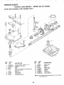
MODEL NUMBER 917.376290
OWNER'SMANUAL
oAssembly
o Operation
o Customer
Responsibilities
o Service
o Adjustments
o Repair Parts
Caution:
Read and Follow
all Safety Rules
and Instructions
Before Operating
This Equipment
153572
Rev, 2 6,6.96
KS/VBL
Printed in UoSoA,
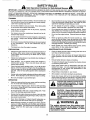
SAFETY
RULES
Practices for
Walk-Behind
Safe Operation
Mowers
IMPORTANT:
THIS CUTTING MACHINE IS CAPABLE OF AMPUTATING
HANDS AND FEET AND THROWING OBJECTS..
FAILURE TO OBSERVE THE FOLLOWING
SAFETY INSTRUCTIONS
COULD RESULT IN SERIOUS INJURY OR DEATH.
SAFETY STANDARDS REQUIRE OPERATOR PRESENCE CONTROLS TO MINIMIZE THE RISK OF INJURY. YOUR UNIT IS
EQUIPPED WITH SUCH CONTROLS,
DO NOT ATTEMPT TO DEFEAT THE FUNCTION OF THE OPERATOR PRESENCE
CONTROLS UNDER ANY CIRCUMSTANCES.
TRAINING:
•
Read this operator's manual carefully. Become familiar with
the controls and know how to operate your mower properly.
Learn how to quickly stop mower_
•
Do not continue to run your mower if you hit a foreign object
Follow the procedure outlined above, then repair any damage before restarting and operating you mower.,
•
Do not allow children to use your mower. Never allow adults
to use mower without proper instructions..
°
Do not change the governor settings or overspeed
engine, Engine damage or personal injury may result.
•
Keep the area of operation clear of all persons, especially
small children and pets_
•
•
Use mower only as the manufacturer
scdbed in this manual.
Do not operate your mower if it vibrates abnormally. Excessive vibration is an indication of damage; stop the engine,
safely check for the cause of vibration and repair as required.
intended and as de-
Do not run the engine indoors.
the
Exhaust fumes are danger-
OUS,,
•
Do not operate mower if it has been dropped or damaged in
any manner. Always have damage repaired before using
your mower.
,,
Do not use accessory attachmentsthat are not recommended
by the manufacturer..
Use of such attachments may be
hazardous.
Never cut grass by pullingthe mower towardsyou.. Mow
acrosstheface of slopes, never up and downor you might
Ioseyourfootingo
Do notmow excessivelysteepslopes. Use
cautionwhenoperatingthemower on uneventerrainorwhen
changing directions- maintaingood footing°
•
Never operate your mower withoutproper guards,plates,
grasscatcheror othersafety devicesin place.
•
The blade turns when the engine is running.
PREPARATION:
MAINTENANCE
•
°
Check the blade and the engine mounting bolts often to be
sure they are tightened properly.
•
Check all bolts, nuts and screws at frequent intervals for
proper tightness to be sure mower is in safe working condition,
•
Keep aU safety devices in place and working_
•
To reduce fire hazard, keep the engine free of grass, leaves
or excessive grease and oil.,
•
Check grass catcher often for' deterioration and wear and
replace worn bags,. Use only replacement bags that are
recommended by and comply with specifications of the
manufacturer of your mower_
•
Always keep a sharp blade on your mower_
•
Allow engine to cool before storing in any enclosure.,
•
Never store mower with fuel in the tank inside a building
where fumes may reach an open flame or an ignition source
such as a hot water heater, space heater', clothes dryer, etc.
Always thoroughly check the area to be mowed and clear it of
all stones, sticks, wires, bones, and other foreign objects.
These objects witl be thrown by the blade and can cause
severe injury.
•
Always wear safety glasses or eye shields when starting and
while using your mower.
•
Dress properly
Do not operate mower when barefoot or'
wearing open sandals. Wear only solid shoes with good
traction when mowing.
•
Check fuel tank before starting engine° Do not fill gas tank
indoors, when the engine is running or when the engine is hot.
Allow the engine to cool for several minutes before filling the
gas tank. Clean off any spilled gasoline before starting the
engine.
•
°
Always make wheel height adjustments before starting your
mower. Never attempt to do this whi_e the engine is running
Mow only in daylight or good artificial light.
OPERATION:
•
°
•
Look
Keep your eyes and mind on your mower and the area being
cut Do not let other interests distract you_
Do not mow wet or slipper? grass_ Never run white operating
your mower,, Always be sure of your footing- keep a firm hold
on the handles and walk.
Do not put hands or feet near or under rotating pads.
clear of the discharge opening at all times..
Keep
•
Always stop the engine whenever you leave or are not using
your mower, or before crossing driveways, walks, roads, and
any gravel-covered areas.
•
Never direct discharge of material toward bystanders nor
allow anyone near the mower while you are operating iL
•
Before cleaning, inspecting, or repairing your mower, stop the
engine and make absolutely sure the blade and all moving
parts have stopped° Then disconnect the spark plug wire and
keep it away from the spark plug to prevent accidental
starting,
AND STORAGE:
A •
I
A
_m,am
O,t
portant safety precautions.
CAUT;ONH!
BECOMEALERT!H
It means
YOUR
for this Sym'b0'i"'topoint
SAFETY
im-
IS INVOLVED.
,,,,,,,,,,,,,,,,,,,,,,,,,,,,,,,,,,,,,
CAUTION:
Always disconnect
spark
plug wire and place wire where it cannot contact spark plug in order to prevent accidental
starting when setting
up, transporting, adjusting or making
repairs.
ill
ii
A WARNING A
The engine exhaust from this product contains ctiemicals known to the State of California to cause cancer, birth defects, or other
reproductive
harm.
PRODUCT
CONGRATULATIONS
on your purchase of a Sears Lawn
Mower. It has been designed, engineered and manufactured to give you the best possible dependability and
performance..
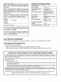
SPECDFICATIONS
HORSEPOWER:
6,0
DISPLACEMENT:
12 56 CU. IN.
Should you experience any problem you cannot easily
remedy, please contact your nearest Sear..4 Authorized
Service CentedDepartment.
We have competent, welltrained technicians and the p roper tools to service or repair
this lawn mower.
GASOLINE CAPACITY
AND TYPE:
1 25 QUARTS
UNLEADED REGULAR
OIL TYPE (API-SF/SG):
SAE 30 (ABOVE 32°F)
SAE 5W-30 (below 32°F)
Please read and retain this manual. The instructions will
enable you to assemble and maintain your lawn mower
properly., Always observe the "SAFETY RULES",,
OIL CAPACITY:
20 OZS.
SPARK PLUG:
(GAP: .030")
CHAMPION J19LM, RJ19LM
STD361458
VALVE CLEARANCE:
INTAKE:
008"
EXHAUST: .008"
MODEL
NUMBER
917°376290
SERIAL
NUMBER
SOLID STATE IGNITION
AIR GAP:
,,0125 IN,
DATEOFPURCHASE
BLADE BOLT TORQUE:
35-40 FT, LBS,,
THE MODELAND SERIAL NUMBERSWILL BE FOUND
ON A DECAL ATTACHED TO THE REAR OF THE
LAWN MOWER HOUSING
YOU SHOULD RECORD BOTH SERIAL NUMBER AND
DATE OF PURCHASE AND KEEP IN A SAFE PLACE
FOR FUTURE REFERENCE,
MAINTENANCE
A Sears Maintenance
CUSTOMER
AGREEMENT
Agreement is available on this product° Contact your nearest Sears store for details.
RESPONSIBILmTIES
o
Read and observe the safety rules.
o
Follow a regular schedule in maintaining, caring for and using your lawn mower.
°
Follow the instructions under "Customer Responsibilities"
LIMITED TWO YEAR WARRANTY
and "Storage" sections of this owner's manual.
ON CRAFTSMAN
POWER MOWER
For two years from date of purchase, when this Craftsman Lawn Mower is maintained, lubricated, and tuned up
according to the operating and maintenance instructions in the owner's manual, Sears will repair free of charge any
defect in material or workmanship.
If this Craftsman Lawn Mower is used for commercial or rental purposes, this warranty applies for only 90 days from
the date of purchase.
This Warranty does not cover:
o
Expendable items which become worn during normal use, such as rotary mower blades, blade adapters, belts,
air cleaners and spark plugo
o
Repairs necessary because of operator abuse or negligence, including bent crankshafts and the failure to maintain
the equipment according to the instructions contained in the owner's manual..
WARRANTY SERVICE IS AVAILABLE BY RETURNING THE CRAFTSMAN POWER MOWER TO THE NEAREST
SEARS SERVICE CENTER/DEPARTMENT
IN THE UNITED STATES. THIS WARRANTY APPLIES ONLY WHILE
THIS PRODUCT IS IN USE IN THE UNITED STATES.
This Warranty gives you specific legal rights, and you may also have other rights which vary from state to state..
SEARS, ROEBUCK AND CO., D/817 WA, HOFFMAN ESTATES, ILLINOIS 60179
3
TA
L
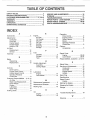
OF CONTENTS
SAFETY RULES ............................................................
2
PRODUCT SPECIFICATIONS ......................................
3
CUSTOMER RESPONSIBILITIES ..................... 3, 12-14
WARRANTY ...................................................................
3
ASSEMBLY ....................................................................
6
OPERATION ..................................................................
8
MAINTENANCE SCHEDULE .....................................
12
SERVICE AND ADJUSTMENTS ................................
15
STORAGE ...................................................................
17
TROUBLESHOOTING .................................................
19
REPAIR PARTS - LAWN MOWER ........................ 20-24
REPAIR PARTS - ENGINE ....................................
25-28
PARTS ORDERING/SERVICE ...................................
30
E
A
Operation:
Accessories ..........................................................
5
Engine:
Drive Control ............................. 9
Air Filter .................................................
14
Engine Control ........................... 9
Adjustments:
Oil Change ....................................................
14
Grass Catcher. ..............................9
Carburetor ........................................................
16
Oil Level .......................................14
Mower. .............................................9
Drive Belt ..........................................................
15
Oi!
Type
.........................................................
14
Operator
Presence
Engine Speed ......................................
16
Starting ..................................... 10
Control Bar ......................................
9
Handle Height ..........................................
16
Stopping
.......................................................
10
Options:
Height of Cut .................................................
9
Storage ............................................................
16
Accessories ............................... 5
Air Filter:
Replacement ........................................
14
F
R
Service ..............................................
14
Fuel:
Repair Parts:
Assembly ..................................................................
6
Capacity ................................... 3
Engine ..........................................
25-28
Storage .......................................................
16
Lawn Mower° .........................20-24
B
Type ...........................................................
:......10
Responsibilities, Customer o..3, 12-14
Blade:
Sharpening ..................................................
13
H
S
Replacement .........................................
13
Handle Adjustment:
Safety Rules ........................................ 2
Assembly ..........................................
6
C
Service and Adjustments .................15
Cutting Height ..........................................
16
Controls:
Calburetor. ............................................
t6
Drive Control ..............................................
8
Drive Belt ..........................................
t5
L
Engine Zone Control .............................
8
Engine
Speed
.............................16
Lubrication:
Handle ....................................... 16
Engine Speed Control ........................
8
Engine .............................................
14
Operator Presence
Lawn Mower, ........................................
t2
Spark Plug ......................................... 14
Control Bar° ................................. 8
Specifications .............................................
3
Customer Responsibilities ....3, 12-14
Speed Control:
Air Filter .................................................
14
M
Engine ......................................... 8
Blade Care/Replacement ..........13
Maintenance Agreement, ...................3
Starting the Engine ...........................10
Drive Wheels ..................................
13
Maintenance Schedule .......................
12
Engine ................................................
14
Stopping the Engine ..........................10
Mowing Tips ..................................................
10
Lubrication ......................
.....................
14
Storage .....................................................
16
Spark Plug .......................................
14
O
Cutting Levels .............................................
9
T
Oil:
Trouble Shooting Chart ....................19
Engine ..................................................
12
Storage ............................................
I6
W
Warranty .................................................
3
4
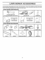
LAWN MOWE
ACCESSORIES
, llll,,ll ,ll,,,i,i ,,,i,,,,i,i,,I,H,I
..........
_
Li ii
_lLi
These accessories were available when this lawn mower was produced. They are also available at most Sears retail out_ets
and service centers,. Most Sears stores can also order repair parts for you, when you provide the model number of you r lawn
mower.. Some of these accessories may not apply to your lawn mower.
LAWN MOWER PERFORMANCE
J
CLIPPING DEFLECTOR
FOR REAR DISCHARGE LAWN MOWERS
MULCHER KITS
STABILIZER
iml!
GRASS CATCHERS
FOR
REAR DISCHARGE
LAWN MOWERS
Jl_
GRASS
FOR
CATCHERS
SIDE DISCHARGE
LAWN MOWERS
GAS CANS
LAWN MOWER MAINTENANCE
........
::::: ...................
,H,, ,,, ,_,,, ,,,
MUFFLERS
BELTS
AIR FILTERS
BLADES
BLADE ADAPTERS
5
SPARK PLUGS
WHEELS
ENGINE OIL
.......
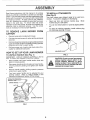
ASSEM
Read these instructions and this manual in its entirety
before you attempt to assemble or operate your new lawn
mower. Your- new lawn mower has been assembled at the
factory with the exception of those parts left unassembled
for shipping purposes. All parts such as nuts, washers,
bolts, etc, necessary to complete the assembly have been
placed in the parts bag° To ensure safe and proper
operation of your lawn mower, all parts and hardware you
assemble must be tightened securely_ Use the correct
tools as necessary to ensure proper tightness.
TO REMOVE
CARTON
LAWN
MOWER
Remove loose parts included with mower..
o
Cut down two end corners of carton and lay end panel
down flat
o
Remove all packing materials except padding between
upper and lower handle and padding holding operator
presence control bar to upper handle..
Roll fawn mower out of carton and check carton thor*
oughly for additional loose parts
=
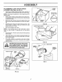
SET UP YOUR
TO UNFOLD
HANDLE
LAWN
(See Fig. 2)
Your lawn mower was shipped ready to be used as a
mulcher,, To convert to bagging or discharging:
o
Open rear' door and remove mulcher plug.
mulcher plug in a safe place.
•
You can now install catcher or optional clipping deflector..
o
To return to mulching operation, install rnulcher plug
into discharge opening of mower.
I
FIG. 2
(See Fig. 1)
o
Raise handles untit lower handle section Iocks into
place in mowing position
°
Raise upper handle section into place on lower handle,
remove protective padding and tighten both handle
knobs
o
Remove handle padding holding operator presence
control bar to upper handle.
Your lawn mower handle can be adjusted for your
mowing comfort,
Refer to "Adjust Handle" in the
Service and Adjustment section of this manual.
..................
i,[i,,lll
, , ii ,,i,,,ll
CAUTION: Do not run your lawn mower
without mulcher plug in place or approved clipping deflector or grass
catcher in place. Never attempt to operate the lawn mower with the rear door
removed or propped open.
OPERATOR PRESENCE
CONTROLBAR
UPPER HANDLE
LIFT UP
MOWING POSITION
LOWER
Store
MOWER
IMPORTANT: UNFOLD HANDLES CAREFULLY SO AS
NOT TO PINCH OR DAMAGE CONTROL CABLES.
.
ii ,,11
ATTACHMENTS
MULCHER
HOWTO
, i ,
LY
TO INSTALL
FROM
•
:,m,,l:
HANDLE
FIG. 1
6
,
..........
i
LY
TO ASSEMBLE
AND
ATTACH
CATCHER
Figs.
3A thru
o
(See
GRASS
LOWER
=RAME
4)
Insert leg of tubular frame through front opening of
grass catcher and thread frame into sewn hem of bag°
{Frames must
be fully seated)
NOTE: Keep bag hem gathered on the straight leg of the
tubular frame.
°
When frame comes out the other end of sewn hem,
immediately work the end of frame down inside the bag
as shown in inset°
•
Slide sewn hem evenly around the tubular frame until
both ends of frame are exposed out of the front opening
Assemble lower frame to tubular frame as shown° Be
sure handle is outside of bag and frames are fully
seated as shown in inset,.
•
°
TUBULAR
FRAME
i
FIG. 3B
LOWER FRAME HANDLE
Slip vinyl bindings over frame..
NOTE: if vinyl bindings are too stiff, hold them in warm
water for a few minutes, If bag gets wet, let it dry before
using_
o
Close the flip lid_ Flip lid must be closed while operating
lawn mower°
°
Lift the rear door on the mower housing and place the
grass catcher frame onto the formed tabs on the rear
door hinge bracket,.
o
The grass catcher is secured to the lawn mower
housing when the rear door is lowered onto the grass
catcher frame..
'
\
FIG. 30
illl,,,,llllll,,lll,,i,,lll,i,,
,11,i I L ,
CAUTION: Do not run your lawn mower
without clipping deflector or approved
grass catcher in place. Never attempt
to operate the lawn mower with the rear
door removed or propped open.
....................................
........
TUBULAR
FRAME
II
i,
_
DOOR
BRACKET
GRASS
CATCHER
FRAME
i
SEWN
FORMED
TABS
FIG. 4
SEWN HEM
FLIP LID
FIG. 3A
OPERATION
ii
:
.............
::':l,,,t,i,
:1
rl
I
I....
I
_1111
"_111 IIII
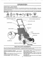
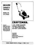
KNOW YOUR LAWN MOWER
READ THIS OWNER'S MANUAL AND SAFETY RULES BEFORE OPERATING YOUR L_WN MOWER, Compare the
illustrations with your lawn mower to familiarize yourself with the location of various controls and adjustments. Save this
manua! for future reference
-,
....
................ iii
These symbols
their meaning.
, , ,
it
may appear on your lawn mower or in literature
CAUTION
OR WARNING
ENGINE
ON
ENGINE
OFF
ENGINE ZONE CONTROL
FAST
SLOW
CHOKE
CABLE
supplied
II
i
iiilulu
with the product.
FUEL
OIL
i
Learn and understand
DANGER, KEEP HANDS
AND FEET AWAY
OPERATOR
PRESENCE
DRIVE CONTROL
CONTROL
BAR
LEVER
STARTER HANDLE
HANDLE KNOB
GASOLINECAP
GRASS
CATCHER
PRIMER
ENGINE SPEED CONTROL
DRIVE COVER
MULCHER
PLUG
ENGINE OIL CAP W/DIPSTICK
HOUSING
WHEEL ADJUSTER
(ON EACH WHEEL)
,l:,l,ll,,,J,,l
,l! "l
! 'l! J'l !, l,j
!JJ lJJ
±
±
_
-
MEETS CPSC SAFETY
!IIIIIII,IUIIIIIII
........
; Lj:::::::
:
REQUIREMENTS
Sears rotary walk-behind power lawn mowers conform to the safety standards of the American National Standards Institute
and the U=S. Consumer Product Safety Commission
Tile blade turns when the engine is running.
OPERATOR PRESENCE CONTROL
° must be held
down to the handle to start the engine Release to stop the
engine_
DRIVE CONTROL LEVER - used to engage power-propelled forward motion of lawn mower.
ENGINE SPEED CONTROL - located on the Side of the
engine which allows you to select either fast (_) or slow
(._.) engine speed.
PRIMER - pumps additional fuel from the carburetor to the
cylinder for use when starting a cold engine.
STARTER HANDLE - used for starting the engine
8
MU LCHER PLUG - must be removed to convert to bagging
or discharging operation.
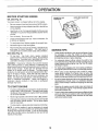
OPERATION
The operation of any tawn mower can result in foreign objects thrown into the eyes, which can
result in severe eye damage, Always wear safety glasses or eye shields while operating your
lawn mower or performing any adjustments or repairs. We recommend a wide vision safety
mask over the spectacles or standard safety glasses,
_
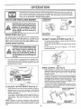
HOW TO USE YOUR LAWN MOWER
LOWER
WHEELS
FOR HIGH CUT
PLATE TAB
CAUTION: Do not run your lawn mower
without mulcher plate in place and door
closed or without an approved clipping
deflector or grasscatcher
in place.
Never attempt to operate the lawn
mower with the rear door removed or
propped open,
,_
ENGINE
SPEED
EVER
RAISE WHEELS
FOR LOW CUT
(See Fig. 5)
FIG. 6
The engine speed is controlled by a lever located on the
side of the engine,, Fast (._) position is for starting the
engine, normal cutting, and better grass bagging. Slow
(,_) position is for light cutting, trimming and fuel economy,
ENGINE
ZONE
TO EMPTY
•
CONTROL
.
CAUTION: Federal regulations require
an engine control to be installed on this
lawn mower in order to minimize the
risk of blade contact injury, Do not
under any circumstances attempt to
defeat the function of the operator control. The blade turns when the engine is
running.
•
GRASS
CATCHER
(See Fig. 7)
To remove grass catcher, release operator presence
control bar to stop engine,,
Lift up rear door and remove the grass catcher by the
handle.
Do not drag the bag when emptying;
it will cause
unnecessary wear,,
Your lawn mower is equipped with an operator presence control bar which requires the operator to be
positioned behind the lawn mower handle to start and
operate the lawn mower,
FIG. 7
DRIVE CONTROL
°
ENGINE SPEED
CONTROL LEVER
°
PRIMER
.
FIG. 5
TO ADJUST
CUTTING
HEIGHT
(See Fig. 6)
Raise wheels for low cut and lower wheels for high cut.
Wheels are set in low cut for shipping_ Adjust cutting
height to suit your requirements° Medium position is
best for most lawns,
•
To change cutting height, squeeze adjuster lever toward wheel° Move wheel up or down to suit your
requirements,
Be sure all wheels are in the same
setting°
NOTE: Adjuster is properly positioned when plate tab
inserts into hole in lever. Also, 9-position adjusters (if so
equipped) allow lever to be positioned between the plate
tabs,
(See Fig. 8)
Self-propelling is controlled by holding the operator
presence control bar down to the handle and pushing
the drive control lever forward until it clicks; then
release the levers
Forward motion will stop when the operator presence
control bar is released. To stop forward motion without
stopping engine, release the operator presence control
bar slightly until the drive control disengages. Hold
operator presence control bar down to handle to continue mowing without self-propelling
To keep drive control engaged when turning corners,
push down on handle and lift front wheels off ground
while turning lawn mower.
.
=
OPERATOR PRESENCE
CONTROL BAR
DRIVE
CONTROL
DRIVE CONTROL
DISENGAGED
TO ENGAGE
DRIVE CONTROL
FIG. 8
9
OPERATIO
BEFORE STARTING
ENGINE
ENGINE OIL CAP
GASOLINE
FILLER CAP
W/DIPSTICK
OIL (See Fig. 9)
Your lawn mower is shipped without oil in the engine°
.
Be sure mower is level and area around oil flit is clean.
o
Ren'love engine oil cap w!dipstick and fill to the full line
on the dipstick.,
•
Use20ozs. of oil. For type and grade of oil to use, see
"ENGINE" in Customer Responsibilities section of this
manual,.
.
.
Pour oil slowly Do not over fill,.
Check oil level before each use_ Add oil if needed, Fill
to full line on dipstick_
°
To read proper level, tighten engine oil cap each time,
o
Reinstall engine oil cap and tighten,
.
After the first two (2) hours of mowing, change the oil,
and every 25 hours thereafter,, You may need to
change the oil more often under dusty, dirty conditions,
FIG. 9
MOWING TIPS
GAS (See Fig. 9)
.
Fill fuel tank,. Use fresh, clean, regular unleaded
gasoline with a minimum of 87 octane. Do not mix oil
with gasoline Purchase fuel in quantities that can be
used within 30 days to assure fuel freshness,
WARNING:
Experience indicates that alcohol blended
fuels (called gasohol or-using ethanol or methanol) can
attract moisture which leads to separation and formation of
acids during storage, Acidic gas can damage the fuel
system of an engine while in storage, To avoid engine
problems, the fuel system should be emptied before storage of 30 days or longer. Drain the fuel tank, start the
engine and let it run until fuel lines and carburetor are
empty. Use fresh fuel next season, See Storage Instructions for additional information,
Never use engine or
carburetor cleaner products in fuel tank or permanent
damage may occur_
TO START ENGINE
Move engine speed control lever to fast (,_) position,.
°
Hold operator presence control bar down to the handle
and pull starter-handle quickly_ Do not allow starterrope to snap back
°
To stop engine, release operator presence control bar',
Under certain conditions, such as very tall grass, it may
be necessary to raise the height of cut to reduce
pushing effort and to keep from overloading the engine
and leaving clumps of grass clippings,
•
For extremely heavy cutting, reduce the width of cut
and raise the rear of the lawn mower' housing one (1)
wheel adjuster setting higher than the front for better
discharge of grass.
•
For better grass bagging and most cutting conditions,
the engine speed should be set in the fast (@) position.
-
When using a rear discharge lawn mower in moist,
heavy grass, clumps of cut grass may not enter the
grass catcher. Reduce ground speed (pushing speed)
and/or run the lawn mower over the area a second time.
•
If a trail of grass clippings is left on the right side of a rear
discharge lawn mower, mow in a clockwise direction
with a small overlap to collect the clippings on the next
pass._
Keep top of engine around starter clear and clean of
grass clippings and chaff. This will help engine airflow
and extend engine life.
=
To start a cold engine, push primer five (5) times before
trying to start° Use a firm push, This step is not usually
necessary when starting an engine which has already
run for a few minutes°
•
-
•
NOTE: tn cooler weather it may be necessary to repeat
priming steps,, tn warmer weather over priming may cause
flooding and engine will not start, if you do flood engine,
wait a few minutes before attempting to start and do not
repeat priming steps,
10
Pores in cloth grass catchers can become filled with dirt
and dust with use and catchers will collect less grass.
To prevent this, regularly hose catchers off with water
and let dry before using.
OPERATION
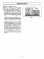
MULCHUNG MOWBNG TgPS
IMPORTANT:
FOR BEST PERFORMANCE,
KEEP
MOWER HOUSING FREE OF BUILT-UP GRASS AND
TRASH,,
SEE
"CLEANING"
tN
CUSTOMER
RESPONSIBILITIES SECTION OF THtS MANUAL.
o
The special mulching blade will recur the grass clippings many times and reduce them in size so that as
they fall onto the lawn they will disperse into the grass
and not be noticed, Also, the mulched grass will
biodegrade quickly to provide nutrients for the lawn.
Always mulch with your highest engine (blade) speed
as this will provide the best recutting action of the
blades,
•
Avoid cutting your lawn when it is wet, Wet grass tends
to form clumps and interferes with the mulching action,
The best time to mow your lawn is the early afternoon,
At this time the grass has dried and the newty cut area
will not be exposed to the direct sun,
°
For best results, adjust the lawn mower cutting height
so that the lawn mower cuts off only the top one-third
of the grass blades (See Fig° 10), If the lawn is
overgrown it will be necessary to raise the height of cut
to reduce pushing effort and to keep from overloading
the engine and leaving clumps of mulched grass. For
extremely heavy mulching, reduce your width of cut by
overlapping previously cut path and mow slowly.
,,
Certain types of grass and grass conditions may require that an area be mulched a second time to completely hide the clippings. When doing a second cut,
mow across or perpendicular to the first cut path
Change your cutting pattern from week to week,, Mow
no rth to south one week the n change to east to west the
next week. This will help prevent matting and graining
of the lawno
"
MAX 1t3
FIG. 10
'1'1
HLmES
,Check for Loose Fasteners
Clean/Inspect
Grass Catcher
::0f Equipped)
..........
MClean
Lawn. Mower
O
E
R
J
........... $f
........ 6/
.............
6/
6/
(Power-Propelled
Clean Under Drive Mowers)
Cover .................
Check drive belt/pulleys
(Power-Propel!ed
Mowers) ...........................
ChecWSharpen/Replace
Lubrication Chart
e,'
........
6/ .........
Blade
6/'3
Clean Battery/Recharge
(E!ec,!,ric ,s,,tart.M,owe_[s,!.,
...............
v'
E
Check Engine O!.1Level
N Change Engine Oil
_
6_1,2
G
Clean Air Filter ..........................................
|
inspect Muffler
N C:iean or Peprace S.park Plug
__......
6/'
_/'
_
E
6/'2
Replace
Air Filter Paper Cartridge
Change more oflen when operating under a heavy load or in high ambient
2 - Service more often when operating
in dirty or dusty conditions.
3 - Replace blades more often when mowing in sandy soil,
4 - Charge 48 hours at end of season
i} =
GENERAL
t
:
t
....
......
,
..._ ..... :
.
temperatures
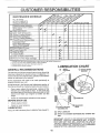
LUBRnCATION CHART
RECOMMENDATIONS
(_)
WHEEL
ADJUSTER
(_) BRAKE SPRING
BRACKET
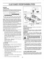
The warranty on this lawn mower does not cover items that
have been subjected to operator abuse or negligence.
To
receive full value from the warranty, operator must maintain
mower as instructed in this manual
Some adjustments
wilt need
properly maintain your unit,.
to be made
periodically
to
Aft adjustments
in the Service and Adjustments
section of
this manual should be checked at least once each season.,
o
Once a year, feptace the spark plug, replace air filter
element and check blade for wear: A new spark plug
and clean/new air filter element assures proper air-fuel
mixture and helps your engine run better and last
longer.
°
Follow
BEFORE
the maintenance
EACH
schedule
in this manual_
ENGINE OIL
USE
°
Check
engine
-
Check
for loose fasteners,
oi! level
(_) HANDLE BRACKET
MOUNTING PIN
LUBRICATION
Keep unit well lubricated
(See "LUBRICATION
REAR DOOR
HINGE
CHART")°
(_)
SPRAY LUBRICANT
(_)
REFER TO CUSTOMER
TIONo
RESPONSIBILITIES
"ENGINE"
SEC-
IMPORTANT:
DO NOT OIL OR GREASE PLASTIC WHEEL
BEARING&
VISCOUS
LUBRICANTS
WILL ATTRACT
DUST AND DIRT THAT WILL SHORTEN
THE LIFE OF
THE SELF LUBRICATING
BEARINGS, iF YOU FEEL THEY
MUST BE LUBRICATED,
USE ONLY A DRY, POWDERED
GRAPHITE TYPE LUBRICANT
SPARINGLY,
12
CUSTOMER
ESPONSl
ILITIES
LAWN MOWER
BLADE
ADAPTER,,.
Always observe safety rules when performing any maintenance°
_-_.,.,
TIRES
o
t
_
_
_
CRANKSHAFT
KEYWAY
Keep tires free of gasoline, oil, or insect control chemP
cals which can harm rubber.
" &W,Iz%S', nes dee
,=rn=0o.
'h'r object=
e' l =°,
e
BLADE
\
CARE
For best results, mower blade must be kept sharp
bent or damaged blades.
Replace
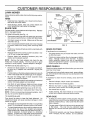
TO REMOVE BLADE (See Fig. 11)
o
°
Disconnect spark plug wire from spark plug and place
wire where it cannot come in contact with spark plug.
Turn lawn mower on its side. Make sure air filter and
carburetor are upo
o
Use a wood block between blade and mower housing
to prevent blade from turning when removing blade
botto
o
Protect your hands with gloves and/or wrap blade with
heavy cloth.
•
Remove blade bolt by turning counter-clockwise
a 9/16" box or open-end wrench,,
°
Remove blade and attaching hardware
washer and hardened washer),
I
i
HARDENED
"\
WAS" "
LOCK WASHER
EDGE
\
X
BLADE
ADAPTER
FIG. 11
GRASS
CATCHER
(If purchased as an accessory)
Use
(bolt, lock
•
hTlelgrvravstscalchedrmaybe hosed with water, but must
•
Check your grass catcher often for damage or deterioration. Through normal use it will wear. If catcher
needs replacing, replace only with a manufacturer
approved replacement catcher., Give the lawn mower
model number when ordering,
NOTE: Remove the blade adapter and check the key
inside hub of blade adapter. The key must be in good
condition to work properly. Replace adapter if damaged,
TO REPLACE BLADE (See Fig., 11)
DRIVE WHEELS
o
Check front drive wheels each time before you mow to be
sure they move freely
Position the blade adapter on the engine crankshaft..
Be sure key in adapter and crankshaft keyway are
aligned.
. LO e' O t
°
•
•
The wheels not turning freely means trash, grass cuttings,
etc, are in the drive wheel area and must be cleaned to free
drive wheels,
IO2e'het 'th !
Be sure the trailing edge of blade (opposite sharp
edge) is up toward the engine..
Install the blade bolt with the lock washer and hardened
washer into blade adapter and crankshaft.
Use block of wood between blade and lawn mower
housing and tighten the blade bolt, turning clockwise.
If necessary to clean the drive wheels, check both front
wheels
•
The recommended tightening torque is 35-40 ft lbs.
IMPORTANT: BLADE BOLT IS GRADE 8 HEATTREATED.
NOTE: We do not recommend sharpening
you do, be sure the blade is balanced.
blade - but if
•
Remove hubcaps, hairpin cotters and washers..
•
Remove wheels from wheel adjusters.
,
Remove any trash or grass cuttings from inside the
dust cover, pinion and!or drive wheel gear teeth.
.
Put wheels back in place
o
If after cleaning, the drive wheels do not turn freely,
contact your nearest authorized service center,.
TO SHARPEN BLADE
GEAR CASE
Care should be taken to keep the blade balanced. An
unbalanced blade will cause eventual damage to lawn
mower or engine.
o
°
o
The blade can b'e sharpened with a file or on a grinding
wheel, Do not attempt to sharpen while on the mower.
To check blade balance, ddve a nail into a beam orwall,
Leave about one inch of the straight nail exposed.
Place center hole of blade over the head of the nail. If
blade is balanced, it should remain in a horizonta!
position, if either end of the blade moves downward,
sharpen the heavy end until the blade is balanced.
To keep your drive system working properly, the gear
case and area around the drive should be kept clean
and free of trash build-up. Clean under the drive cover
twice a season
The gear case is filled with lubricant to the proper level
at the factory.. The only time the lubricant needs
attention is if service has been performed on the gear
case..
•
13
If lubricant is required, use only Texaco Starplex Premium 1 Grease, Part No,. 750355 Do not substitute.
L
ES
ENGNNE
LUBRICATION
Use onty high quality detergent oil rated with API service
classification SF or SG. Select the oil's SAE viscosity grade
according to your expected ope_ating temperature.
SAE VISCOSITY
CONTAINER
GRADES
FIG. 12
COLLAR
-_F
-20 °
°c -30°
0°
30 _
-_0o -4o
TEMPERATURE
32;
40*
0"
RANGE ANTfCIPATED
60 °
1'0o
80 =
2oo
_00 _
10"
4oo
BEFORE NEXT O_L CHANGE
TURN
COUNTERCLOCKWISE
TO REMOVE
NOTE: Although multi-viscosity oils (5W30, 10W30 etc,)
improve starting in cold weather, these multi-viscosity oils
will result in increased oil consumption when used above
32°F. Check your engine oil level more frequently to avoid
possible engine damage from running low on oil,
SLOT
AIR FILTER
Change the oil after the first two hours of operation and
every 25 hours thereafter' or at least once a year if the lawn
mower is not used for 25 hours in one year.
AIR FILTER COVER
TURN CLOCKWISE
TO TIGHTEN
FIG_ 13
Check the crankcase oil level before starting the engine
and after each five (5) hours of continuous use.. Tighten oil
plug securely each time you check the oil level°
MUFFLER
TO CHANGE ENGINE OfL (See Fig, 12)
SPARK
NOTE: Before tipping lawn mower to drain oil, drain fuel
tank by running engine until fue! tank is empty,.
Change your spark plug each year to make your engine
start easier and run better,, Set spark plug gap at .030 inch_
,,
Disconnect spark plug wire from spark plug and place
wire where it cannot come in contact with spark plug.
CLEANING
-
Remove engine oil cap; lay aside on a ctean surface,
,
Tip lawn mower on its side and drain oil into a suitable
container Rock lawn mower back and forth to remove
any oil trapped inside of engine,
,
Wipe off any spifled oil on lawn mower and on side of
engine
.
Fill engine with oil. Fill only to the "FULL" line on the
dipstick. DO NOT OVER FILL
o
Replace engine oil cap,,
.
Reconnect spark plug wire to spark plug
inspect and replace corroded muffler as it could create a
fire hazard and/or damage,
IMPORTANT;
FOR BEST PERFORMANCE,
KEEP
MOWER HOUSING FREE OF BUILT-UP GRASS AND
TRASH.. CLEAN THE UNDERSIDE OF YOUR MOWER
AFTER EACH USE.
ill
Your engine will not run properly and may be damaged by
using a dirty air filter.
Replace the air filter every year, more often if you mow in
very dusty, dirty conditions. Do not wash air filter..
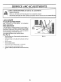
TO CHANGE AIR FILTER (See Fig.. 13)
o
°
o
Removetheairfiltercover
by turning counterclockwise
to the stop and pull away from coIlar.
Remove filter from inside of cover._
Put air filter cover and filter into collar aligning the tab
with the slot,,
.
Push in on cover and turn clockwise to tighten,
i
•
Turn lawn mower on its side.. Make sure air' filter and
carburetor are up.. Clean the underside of your lawn
mower by scraping to remove build-up of grass and
trash.,
=
Clean engine often to keep trash from accumulating., A
clogged engine runs hotter and shortens engine life.
°
Keep finished surfaces and wheels free of all gasoline,
oil,etco
•
We do not recommend using a garden hose to clean
lawn mower unless the electrical system, muffler, air'
filter and carburetor are covered to keep water' out..
Water in engine can result in shortened engine life.
CLEAN
Clean the inside of the cover and the collar to remove
any dirt accumulation_
Insert new filter into cover,.
o
ii,
from spark plug and place wire where it
cannot
come
in contact spark
with the
CAUTION:
Disconnect
plugspark
wire
plug.
AIR FILTER
=
PLUG
UNDER
DRIVE COVER
Clean under drive Cover at least twice a season_ Scrape
underside of cover with putty knife or' similar tool to remove
any build-up of trash or grass on underside of drive cover.
14
CAUTION:BEFORE
PERFORMING ANY SERVICE OR ADJUSTMENTS:
•
Release control bar.
°
Make sure the blade and all moving parts have completely stopped,
•
Disconnect spark plug wire from spark plug and place where it cannot come in contact with plugo
LAWN MOWER
TO ADJUST
CUTTING
See "TO ADJUST CUTTING
section of this manual,
REAR
HEIGHT
HEIGHT" in the Operation
DEFLECTOR
The rear deflector, attached between the rear wheels of
your lawn mower, is provided to minimize the possibility
that objects will be thrown out the rear of the lawn mower
into the operator's mowing position
If the rear deflector
becomes damaged, it should be replaced.
TO REMOVE/REPLACE
DRIVE
BELT
(See Fig. 14)
•
°
Remove d rive cover Remove belt by pushing down on
gear case pulley..
Turn Iawn mower on its side with carburetor and fuel
cap upo
Remove blade,
o
Remove debris shield,,
o
Remove belt from engine pulley on crankshaft,
•
Install new belt by reversing above steps.
o
Always use factory approved belt to assure fit and long
{ife
•
FIG. 14
15
SEIRVUCE AND ADJUSTMENTS
ii i_11 ,,
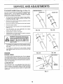
TO ADJUST
HANDLE
(See Figs. 15 Thru 17)
SHIPPING
Your lawn mower handle can be raised or' lowered for' your
mowing comfort.
Four (4) positions are available: high,
medium high, medium tow and low,, Handles are shipped
mounted in the medium low position,
=
To change from medium tow to medium high position,
the upper and lower handle sections will have to be
turned over (See Fig. 15B)._
o
Remove the controls and operator presence control
bar from the upper handle,.
=
Remove the starter rope guide from the lower handle.
=
o
Remove hairpin cotters.
Disconnect the lower handle from the handle brackets
(See Fig, 17)..
Turn the handle over and reassemble the hairpin
cotters that have been removed,.
°
°
Reassemble the starter rope guide.
=
Reassemble the controls and the operator presence
control bar to the upper handle.
POSITION
MEDIUM LOW
MEDIUM
FIG. 15A
HIGH
FIG. 15B
LOW
CAUTION: The operator presence control bar must pivot freely to permit blade
brake engagement when control bar is
released.
Do not over tighten the
fasteners holding the controls to the
upper handle.
To change from medium low to high position only the
upper handle section will have to be turned over (See
Fig.. 16A)._
To change from medium low to tow position, only the
lower handle section will have to be turned over (See
Fig.. 16B)_
FIG. 16A
ENGINE
ENGINE
FIG. 16B
SPEED
LOWER HANDLE
Your engine speed has been factory set.. Do not attempt
to increase engine speed or it may result in personal injury.
If you believe that the engine is running too fast or-too slow,
take your lawn mower to an authorized service center' for
repair and adjustment.
SQUEEZE
TO REMOVE
CARBURETOR
HANDLE
BRACKET
Your carburetor has a non-adjustable fixed main jet for
mixture control, If your engine does not operate properly
due to suspected carburetor problems, take your lawn
mower to an authorized service center for repair and/or
adjustment.
HAIRPIN CLIP
FIG. 17
16
HI,I,.........................
STORAGE
Immediately prepare your lawn mower for storage at the
end of the season or if the unit wi!l not be used for 30 days
or more.
ENGINE
LAWN MOWER
IMPORTANT:
IT IS IMPORTANT
TO PREVENT
GUM
DEPOSITS
FROM
FORMING
IN ESSENTIAL
FUEL
SYSTEM PARTS SUCH AS CARBURETOR,
FUEL FILTER,
FUEL HOSE, OR TANK DURING
STORAGE.
ALSO,
EXPERIENCE
INDICATES
THAT ALCOHOL
BLENDED
FUELS (CALLED
GASOHOL
OR USING ETHANOL
OR
METHANOL)
CAN ATTRACT
MOISTURE
WHICH LEADS
TO SEPARATION
AND FORMATION
OF ACIDS DURING
STORAGE
ACIDIC
GAS CAN DAMAGE
THE FUEL
SYSTEM OF AN ENGINE WHILE IN STORAGE
FUEL SYSTEM
When lawn mower isto be stored for a period of time, clean
it thoroughly, remove all dirt, grease, leaves, etc. Store in
a clean, dry area.
-
Clean entire lawn mower (See "CLEANING" in the
Customer Responsibilities section of this manual)
o
Lubricate as shown in the Customer Responsibilities
section of this manual,
,,
Be sure that all nuts, bolts, screws, and pins are
securely fastened° Inspect moving parts for damage,
breakage and wear. Replace if necessary.
o
Touch up all rusted or chipped paint surfaces; sand
lightly before painting
•
Start the engine and let it run until the fuel lines and
carburetor are empty
o
Never use engine or carburetor cleaner products in the
fuel tank or permanent damage may occur.
Use fresh fuel next season
NOTE:
Fuel stabilizer is an acceptable alternative in
minimizing the formation of fuel gum deposits during storage. Add stabilizer to gasoline in fuel tank or storage
container Always follow the mix ratio found on stabilizer
container_ Run engine at least 10 minutes after adding
stabilizer to allow the stabilizer to reach the carburetor. Do
not drain the gas tank and carburetor if using fuel stabilizer.
You can fold your lawn mower handle for storage_
Squeeze the bottom ends of the lower handle toward
each other until the lower handle clears the handle
bracket, then move handle forwar&
°
Loosen upper handle mounting bolts enough to allow
upper handle to be folded back°
IMPORTANT:
WHEN FOLDING THE HANDLE FOR
STORAGE OR TRANSPORTATION, BE SURE TO FOLD
THE HANDLE AS SHOWN OR YOU MAY DAMAGE THE
CONTROL CABLES
•
Drain the fuel tank
•
HAr,,IDLE (See Fig. 18)
o
°
ENGINE
OIL
Drain oil (with engine warm) and replace with clean engine
oil.. (See "ENGINE"
in the Customer Responsibilities
section of this manual).
When setting up your handle from the storage position,
the lower handle witl automatically lock into the mowing
position.
CYLINDER
LOWER HANDLE
HANDLE
BRACKET
o
Remove spark plug..
-
Pour one ounce (29 ml) of oil through spark plug hole
into cylinder..
°
Pull starter handle slowly a few times to distribute oil,
•
Replace with new spark plug.
OTHER
SQUEEZE TO
FOLD
HAIRPIN
COTTER
•
Do not store gasoline from one season to another..
•
Replace your gasoline can if your can starts to rust.
Rust and/or dirt in your gasoline will cause problems..
•
If possible, store your unit indoors and cover it to give
protection from dust and dirt.
°
Cover your unit with a suitable protective cover that
does not retain moisture Do not use plastic, Plastic
cannot breathe which allows condensation to form and
" will cause your unit to rust..
IMPORTANT: NEVER COVER MOWER WHILE ENGINE
AND EXHAUST AREAS ARE STILL WARM
OPERATOR PRESENCE
CONTROLBAR
UPPER HANDLE
FOLD FORWARD
FOR STORAGE
CAUTION: Never store the lawn mower
with gasoline in the tank inside a building where fumes may reach an open
flame or spark. Allow the engine to cool
before storing in any enclosure.
FOLD BACKWARD
MOWING
POSITION
Ul I I.I
LOWER HANDLE
FIG. 18
17
i i
i
,i...,,
I
I
I
18
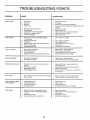
PROBLEM
CAUSE
Does not start
CORRECTION
1
2
3
4
Dirty air filter
Out of fuel,
Stale fuel
Water in fuel
1
2
3
4
5
6
7
8,
9,
Spark plug wire is disconnected
Badspark plug.
Loose blade or broken blade adapter
Control bar in released position
Control bar defective
5_
6.
7,
8.
9
Clean/replace air filter
Fill fue! tank
Drain tank and refitl with fresh clean fuel
Drain fuel tank and carburatorand refilt tank with fresh
gasoline
Connect wire to plug
Replace spark plug
Tighten blade bolt or repiace blade adapter
Depress control bar to handle
Replace control bar
1,
1
Set in "Higher Cut" position,
2
3.
4.
5,
6
Rear of lawn mower housing/blade dragging
in heavy grass
Cutting too much grass
Dirty air filter.
Buildup of grass, leaves and trash under mower
Too much oil in engine
Walking speedtoo fast
2
3
4
5
Set in "Higher Cut" position
Clean!replace air filter
Clean underside of mower housing
Check oil level
6
Cut at slower walking speed
1
2
3
4
Worn, bent or loose blade
Wheelhetghts
uneven,
Low engine speed,
Buildup of grass, leaves, and trash under mower
1
2
3,
4
Replace blade Tighten blade boil
Set all wheels at same height
Set engine speed control in fast position
Clean underside of mower housing
I
2
Replace blade Tighten blade bolt,
Contact authorized service center/department
Depress control bar to upper handle before
pulling starter rope
Contact authorized service center/department
Replace blade adapter
Move lawn mower to cut grass or to hard surface
to start engine,
i
Loss of power
Poor cut - uneven
Excessive
vibration
1
Worn, bent or loose blade
2
Bent engine crankshaft
1
Engine flywheel brake is on when control bar is
released
1
2
3
4
Bent engine crankshaft
Blade adapter broken.
Blade dragging in grass,
2
3
4
Loss of drive
1
2
Drive wheels not turning with drive control engaged
Belt not driving
1
2
Adjust or replace drive control cable, if broken
Put belt on pulleys or replace belts if broken,,
Grass catcher not filling
(if so equipped)
1
2,
Cutting height too low
Lift on blade worn off,
3,
4.
Catcher not venting air
Low engine speed.
1
2
3
4
Raise cutting height
Replace blade
Clean grass catcher
Set engine speed control in fast position
t.
2
1
2,
3
Grass is too high or wheel height is too low
Rear of lawn mower housing/blade dragging
in grass.
Grass catcher too full,
4
Handle height position not right for you.
Raise
Raise
setting
Empty
Adiust
Starter rope hard to pull
Hard to push
19
3
4
cutting height
rear of lawn mower housing one (1)
higher
grass catcher
handle height to suit
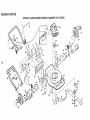
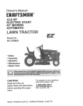
REPAURPARTS
ROTARY LAWN MOWER MODEL
NUMBER
917.376290
6
22
10
14
56
10,
A
12
37
to
o
f
16
12
2O
37
35
31
27
4O
30
52
41
13
35
39
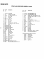
REPAIR PARTS
ROTARY LAWN MOWER MODEL NUMBER
KEY
NO.
t_
PART
NO
1 !45646X479
2 130861
3 74350424
4 150425
5 151517
6 136376
7 STD54t425
8 145793
9 151023
10 128415
11 150050
12 54583
13 150181
14 700483X479
15 700365X479
16 133190X479
17 140661X479
18 73510400
20 140540
22 85543
23 87677
25 83923
27 150341
28 142748
29 62335
30 145935X004
31 701037
32 700331X004
34 146630
35 700325X007
37 150078
DESCRIPTION
Upper Handle
Engine Zone Control Cable
Hex Head Screw 1/4-20 x 1-1/2
Mulcher Plug
Cable Clip
Handle Knob
Locknut 1/4-20
Control Bar
Rear Door Kit
Pop Rivet
Self Tapping Screw #10-16 x 1/2
Hex Tapping Screw w/Sems 1/4-20 x 1/2
Hubcap
Back Plate
Side Baffle
Discharge Baffle
Rear Baffle
Keps Locknut 1/4-20
Rear Skirt
Engine Pulley
Hi-Pro Key #505
Hex Flange Nut
Wheel
Shoulder Bolt 3/8-16 x 1
Spring Washer
Axle Arm Assembly
Selector Knob
Selector Spring
Spacer
Wheel Adiusting Bracket (Right)
Thread Cutting Screw wiSerns 5/16-18 x 3/4
KEY
NO.
PART
NO
39
40
41
44
46
47
48
49
50
51
52
55
56
57
58
59
61
62
64
--
151512X479
151511X479
150406
48413
851514
141114
851074
850263
851084
700869X479
85463
751592
88652
51793
15t516X479
131959
132001
134612
152843
153572
917.376290
DESCRIPTION
Handle Bracket Assembly (Left)
Handle Bracket Assembly (Right)
Hex Head Thread Rolling Screw 3/8-16 x 1-1/8
Lawn Mower Housing (Incl. Key #14, 15, 51 & 52)
Blade Adapter
Blade 22"
Hardened Washer
Helical Washer 3/8-24 x 1-3/8 Gr. 8
Hex Head Machine Screw 3/8-24 x 1-3/8 Gr. 8
Front Baffle
Danger Decal
Locknut 3/8-16
Hinge Screw 1/4-20 x 1-1/4
Hairpin Cotter
Lower Handle
Handle Bolt
Rope Guide
Debris Shield
Engine-Craftsman - Model No. 143.966010
Owner's Manual (English/Spanish)
Available accessories not included with tawn mower:
-7_.!.133303
Clipping Deflector
-7_133623
Gas Can (2.5 gal.)
-71 335O0
Fuel Stabilizer
-7__133300
SAE 30W Oil (20 oz.)
-7___133417
Dust Shield
Mower Cover
-7_$133316
-7_.!.133723
High Wheel Kit
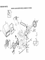
REPASR PARTS
ROTARY LAWN MOWER MODEL
NUMBER
917.376290
--2
54
11
/
18
14
53
18
10
14
8
12
13
16
10
13
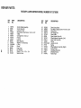
REPAaR PARTS
ROTARY LAWN MOWER MODEL NUMBER 917.376290
KEY
NO.
l'O
Co
1
2
3
4
5
6
8
9
10
tl
12
13
14
15
16
18
PART
NO.
145755
48385
636O1
144929
146527
700875
150182
145212
88446
t50340
12000058
137054
88080
88118
67725
701037
DESCRIPTION
Control Cable Assembly
Control Head Kit
Locknut #10-24
HexWasher Head Scow 1/4-20 x 2.t2
V-Belt
Carriage Bolt 1/4-20 x 2
Hubcap
Locknut
Nylon Bushing
Wheel& Tire Assemb_y
E-Ring
Pinion
Dust Cover
Felt Washer
Washer t/2x 1-1/2 x .134
Selector Knob
KEY
NO.
PART
NO.
25
26
28
3t
32
33
35
36
37
38
40
41
53
54
55
57
152903
143603
702806
132010
137052
48386
151521
702511
146467
STD541425
75192
151520
144747
149844
86012
144748
DESCRIPTION
Ddve Cover Decal
Pan Head Tapping Screw #10-24 x 2-3/4
Drive Cover
Hex Flange Nut
Drive Pulley
Drive Control Cable Kit
Wheel Adjuster Assembly (Left)
Gear Case Assembly
Spring
Locknut 1/4-20
Spring
Wheel Adjuster Assembly (Right)
Frame Throat
Grassbag Assembly
Driveshaft Cover
Frame Tube
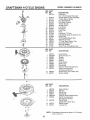
REPAIR PARTS
ROTARY LAWN MOWER - - MODEL NO. 917.376290
GEAR
CASE ASSEMBLY
PART NUMBER
702511
17
15
10
14
18
J
10
9
KEY
NOo
PART
NO.
1
2
3
4
6
17490416
137055X004
137053
57072
48373
7
8
9
10
77881
137051
137O74
57079
DESCRIPTION
Tapping Screw 1/4-20 x 1-1/4
Engagement Bracket
Shifter
Seal
Gear Case Halves Kit (Includes Key
Nos_ 4, 5, and 7)
Bearing
Worm Shaft
Drive Shaft
Hardened Washer
KEY
NO.
PART
NO.
DESCRIPTION
1t
I2
13
14
15
16
17
18
19
131484
700343
86447
137050
750436X
750369
12000003
850848
81585X004
Clutch Yoke
Bushing
Ptug
Helical Gear
Clutch Jaw
Grease
E-Ring
Hi-Pro Key
Spring Bracket
NOTE:
24
All component dimensions given in U.S. inches.
1 inch = 25_4 mm
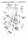
CRAFTSMAN
4=CYCLE ENGINE
MODEL
NUMBER
143.966010
.390
'287
4OO
1
126
120
119
125
/
150
15
14
19
f
a'89
17
45
241
<
/
238
245
25O
25
46
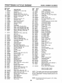
CRAFTS AN
REF
NO.
1
2
6
7
12A
I2B
14
15
16
17
18
19
20
30
40
40
40
41
41
PART
NO.
36478A
26727
33734
36557
36558
34695
28277
30589
32651
31335
650548
36281
32600
358O1
36073
36074
36O75
36O7O
36071
41
36072
42
42
42
43
45
46
48
50
52
69
70
72
73
75
80
81
82
83
86
89
90
92
93
100
101
103
110
119
120
125
125
36076
36O77
36078
2O381
32875A
32610A
27241
35992
29914
35261
34311D
30572
28833
27897
30574A
30590A
30591
30588A
65O488
6110O4
611109
650815
650816
34443A
610118
651007
34961
36477
36476
36471
36472
126
126
130
135
150
151
166
169
172
29314B
29315C
6021A
35395
35991
31673
35827
27234A
32755
4-.CYCLE ENGINE
DESCRIPTION
Cylinder (Inc!. 2,7,20 & 125)
Dowel Pin
Breather Element
Breather Ass'y. (Incl. 6 & 12A)
Breather Cover & Tube (Inclo 12B)
Breather Tube Elbow
Washer
Governor Rod (Incto 14)
Governor LeverGovernor Lever Clamp
Screw, 8-32 x 5/16"
Extension Spring
Oil Seal
Crankshaft
Piston, Pin & Ring Set (Std.)
Piston, Pin & Ring Set (.0!0" OS)
Piston, Pin & Ring Set (.020" OS)
Piston & Pin Ass'y. (Std.) (Incl. 43)
Piston & Pin Ass'y.. (o010" OS)
(lncL 43)
Piston & Pin Ass'y. (_020" OS)
(IncL 43)
Ring Set (Std.)
Ring Set (.010" OS)
Ring Set (,.020" OS)
Piston Pin Retaining Ring
Connecting Rod Ass'y._ (lncL 46)
Connecting Rod Bolt
Valve Lifter
Camshaft (MCR)
Oil Pump Ass'y.
* Mounting Flange Gasket
Mounting Flange (Incl. 72 thru 83)
Oil Drain Plug (Incl. 73)
Drain Plug Gasket
Oil Seal
Governor Shaft
Washer
Governor Gear Ass'yo (IncL 81)
Governor Spool
Screw, 1/4-20 x 1-!/4"
Flywheel Key
Flywheel
Bellevifle Washer
Flywheel Nut
Solid State Ignition
Spark Plug Cover
Screw, Torx T-15, 10-24 x 15/16"
Ground Wire
* Cylinder Head Gasket
Cylinder Head
Exhaust Valve (Std.) (IncL 151)
Exhaust Valve (1/32" OS)
(IncL 151)
Intake Valve (Std.) (IncL 151)
intake Valve (1/32" OS) (incL 151)
Screw, 5/16-18 x 1-1/2"
Resistor Spark Plug (RJ19LM)
Valve Spring
Valve Spring Cap
Engine Shroud
* Valve Cover Gasket
Vatve Cover
MODEL
NUMBER
143.966010
REF
NO.
174
178
182
184
185
186
189
191
195
200
202
203
204
205
207
209
215
223
224
238
239
241
245
250
260
261
262
263A
275
277
285
287
290
292
300
301
305
306
307
309
310
313
347
370A
370B
380
390
400
416
PART
NO.
30200
29752
6201
26756
36544
34337
650839
36559
6!0973
35727
36482
31342
650549
650777
34336
30200
35511
650451
34690A
650932
34338
35797
35066
35065
35826
30200
650831
35821
36473
650988
35000A
650926
34357
26460
35586
36246
35819A
34265
35499
651014
35822
34080
650898A
36261
35167
632733
590702
36481
36085
417
650760
DESCRIPTION
Screw, 10-24 x 9/16"
Nut & Lock Washer, 1/4-28
Screw, 1/4_28 x 7/8"
* Carburetor To Intake Pipe Gasket
Intake Pipe
Governor Link
Screw, 1/4-20 x 3/8"
S..E_ Brake Bracket (Incl. t95)
Terminal
Control Bracket (Incl. 202 thru 205)
Compression Spring
Compression Spring
Screw, 5-40 x 7/16"
Screw, 6-32 x 21/32"
Throttle Link
Screw, 10-24 x 9/16"
Control Knob
Screw, 1/4-20 x 1"
* Intake Pipe Gasket
Screw, 10-32 x 49/64"
* Air Cleaner Gasket
Air Cleaner CoFlar
Air Cleaner Filter
Air Cleaner Cover
Blower-Housing
Screw, 10-24 x 9/16"
Screw, 1/4-20 x 1/2"
Starter Grill
Muffler' (Incl. 277)
Screw, 1/4-20 x 2-5/16"
Starter' Cup
Screw, 8-32 x 21/64"
Fuel Line
Fuel Line Clamp
Fuel Tank (Inct. 292 & 301)
Fuel Cap
Oi! Fill Tube
* "O"-Ring
"O"-Ring
Screw, 10-32 x 7/16"
Dipstick
Spacer
Screw, 10-32 x 27/32"
Lubrication Decal
Control Decal
Carburetor (lncto I84)
Rewind Starter
Gasket Set (Incl. Items Marked *)
Spark Arrestor Kit
(lnct, 416)(Optional)
Screw, 8-32 x 3/8" (Optional)
RPM High 2900 to 3200
RPM Low 2450 to 2750
(NOTE: This engine could have been built with 590739
starter.. Refer !o the design of the rope pulley strength ribs
for part identification.. Individual starter' parts do not
interchange. )
NOTE: All component dimensions given in U,S. inches
1 inch = 25.4 mrn
26
CRAFTSMAN
4=CYCLE ENGBNE
MODEL
NUMBER
143.966010
REF PART
NO, NO.
- - 632733
,,t_
1
2
4
5
6
7
16
25
27
28
29
30
31
35
36
37
40
44
48
_-%1,,
631615
631767
631184
631183
632504
6505O6
631775
631867
631024
632019
631028
631021
631022
36045
632735
632547
632736
27110
631027
DESCRIPTION
Carburetor
(IncL 184 of Engine Parts List)
Throttle Shaft & Lever Assembly
Throttle Return Spring
Dust Seal Washer
Dust Seal (Throttle)
Throttle Shutter
Shutter Screw
Fuel Fitting
Float Bowl
Float Shaft
Float
Float Bowl "O" Ring
inlet Needte, Seat, & Clip (IncL 31)
Spring Clip
Primer Bulb/Retainer Ring
Main Nozzle Tube
"O" Ring, Main Nozzte Tube
High Speed Bowl Nut
BowENut Washer
Welch Plug, Atmospheric Vent
'
REF PART
NO, NO,
-1
2
3
4
5
6
7
8
11
590702
590599A
590600
590696
590601
590697
590698
590699
5907O0
590703
12
t3
590535
5907O1
REF PART
NO. NO.
-3
6
7
8
11
590739
590740
590616
590617
590618A
590638
12
590535
13
14
590701
590741
NOTE:
27
u',,,:ltI
.....i
"lr_
DESCRIPTION
Recoil Starter
Spring Pin (IncL 4)
Washer
Retainer
Washer
Brake Spring
Starter Dog
Dog Spring
Pulley & Rewind Spring Ass'y.
Starter Housing Ass'y..
(40 degree grommet)
Starter Rope ( 98" X 9/64" dia.)
Starter Handle
DESCRIPTION
Rewind Starter
Retainer
Starter Dog
Dog Spring
Pulley & Rewind Spring Ass'y
Starter Housing Ass'y
(40 degree grommet)
Starter Rope
(Length 98" x 9/64" dia.)
Starter Handle
Locking Tab
All component dimensions
1 inch = 25..4 mm
given in UoS. inches
28
ERVICE
29
OTE$
®
OWNE 'S
MA UAL
&0 HORSEPOWER
22" REAR D_SCHARGE
POWER PROPELLED
ROTARY LAWN MOWER
Each lawn mower has its own model number,
gine has its own model number,
MODEL NO=
917.376290
Each en-
The model number for your lawn mower will be found on a
decal attached to the rear of the lawn mower housing.
The model number for your engine will be found on the
blower housing of the engine,
Alt parts listed herein may be ordered from any Sears,
Roebuck and Co,. Service Center/Department and most
Retail Stores.
WHEN ORDERING REPAIR PARTS, ALWAYS GIVE THE
FOLLOWING INFORMATION:
iF YOU NEED
REPAIR SERVICE
OR PARTS:
= PRODUCT-
LAWN MOWER
" MODEL NUMBER - 917o376290
o ENGINE MODEL NO. - 143.966010
FOR REPAIR SERVICE, CALL
THIS TOLL FREE NUMBER:
1-800-4-REPAnR
(1-800-473-7247)
FOR REPLACEMENT PARTS
INFORMATION AND
ORDERING, CALL THIS
TOLL FREE NUMBER:
o PART NUMBER
o PART DESCRIPTION
Your Sears merchandise has added value when you
consider Sears has service units nationwide staffed with
Sears trained technidans .... professional
technicians
specifically trained to insure that we meet our pledge to
you, we service what we sell,
1-800-FON-PART
(1-800-366-7278)
3O