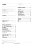
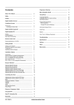
1
AR1500 Operating manual
Power requirement...
AR1500 Operating manual
6V DC from built-in NiCad battery pack or 11 - 18V DC
from CHG jack or 4 x AAA dry cells (dry case provided)
100mA approx
55mm (W) x 152mm (H) x 40mm (D) approx excluding
projections
360g approx including NiCad pack
Liquid Crystal (LCD) with switchable light for areas of
low level lighting
Power consumption...
Size...
Weight...
Display...
** Specifications subject to change without notice due to continuous
development of the receiver. E&OE.
32
Every effort has been made to make this manual correct and up to date. Due to continuous
development of the receiver and by error or omissions anomalies may be found and this is
acknowledged.
Although carefully designed, the receiver (like all receivers) suffers from internal noises
known as spurii. They are a product of the receiver’s circuitry and do not represent a fault.
copyright 1
corruption 30
cross-modulation 8
DA3000 31
DA900 8, 10
defaults 26
DELAY 14, 20, 25
DELAY/HOLD 14
DIAL 9, 20, 26
discone 8
DOWN ARROW 13, 20
dry batteries 6
DX 10
The AR1500 is designed to be particularly sensitive for hand-held operation, for this
reason strong signal mixing or overload may be experienced if used in strong signal areas
or when connected to an externally mounted aerial such as a discone, microprocessor
noise may also be audible on certain frequencies and modes.
This manual is protected by copyright AOR (UK) Ltd 1992, 1993. No information contained
in this manual may be copied or transferred by any means without the prior written consent of
AOR (UK) Ltd.
© 1991, 1992, 1993 AOR (UK) Ltd.
29
BANK 13, 21
Bank 9 26
banks 22
BATT 7
batteries 6
battery compartment 6, 7
Beat Frequency Oscillator 9
BFO 9, 10
breakthrough 8
Broadcast 16
cables 6
Charger 14
charger 6, 7
CHG 14
clean 6
CLEAR 12, 21
Clearing 15
Clearing memories 21
Controls 9
Conventions 14
Thank you for purchasing the AOR AR1500 compact all mode hand portable receiver. The
AR1500 is a highly sophisticated piece of equipment using the very latest in electronics design
and technology. It is important that you carefully read this handbook and familiarise yourself
with the receiver before placing it into operation.
Most apparent faults are due to accidental misoperation of the receiver, carefully read all of
the manual before deciding to return the receiver for repair.
(14) Index
AC mains supply 6
accessories 31
Aerial 8
Aerial connection 8
Aerial input 10
Aerial Tuning Units 8
Airband 16
AM 15, 16
AM/FM 13
Amateur band 16
ANT 10
ARROW 13, 20
attenuator 8, 10
ATU 8
auto memory 19
Automatic memory input
AUX 21, 22
(1) Introduction & accessories
EAR 10
Earphone 10
EARTH 6
EEPROM 19
ENTER 12
Entering 15
1-1 Accessories supplied
DA900
SW-wire
AC charger
Internal NiCad
Dry battery case
12V DC lead
Soft case
Belt hook
Earphone
Operating manual
FM 15, 16
Fr.Err 15
Frequency list 16
Front panel 12
fuse 6
ground
6
HOLD
14, 20, 21, 25
internal NiCad pack
jack socket
7
single wide band whip aerial for VHF and UHF
aerial wire terminated in a BNC plug for shortwave
rechargeable battery pack
(to house 4 x AAA Alkaline cells)
fitted with a cigar lighter plug for mobile operation
This manual covers the AR1500, AR1500E
and AR1500EX models.
6
1
AR1500 Operating manual
AR1500 Operating manual
(2) Table of Contents
(1)
1-1
Introduction & accessories....................................................................................
Accessories supplied................................................................................................
1
1
(2)
Table of contents (this page)...................................................................................
2
(3)
Major features........................................................................................................
4
(4)
4-1
4-2
4-3
4-4
Precautions.............................................................................................................
Location...................................................................................................................
Look after your receiver...........................................................................................
Power requirements..................................................................................................
Aerial connection.....................................................................................................
6
6
6
6
8
(5)
5-1
Controls and functions...........................................................................................
Top panel.................................................................................................................
Close-up views of the AR1500..................................................................................
Front panel ...............................................................................................................
CHG - Charger input socket......................................................................................
9
9
11
12
14
Basic operation........................................................................................................
Background..............................................................................................................
Conventions..............................................................................................................
Basic manual operation............................................................................................
1.
Entering a frequency through the keypad.........................................................
2.
Clearing incorrect frequency input...................................................................
3a. Changing mode................................................................................................
3b. Frequency list audible from various parts of the UK: .......................................
4.
Tuning the receiver...........................................................................................
14
14
14
15
15
15
15
16
17
Single Side Band Operation ...................................................................................
18
5-2
5-3
(6)
6-1
6-2
6-3
(7)
Notes:
This procedure resets the microprocessor and clears the contents from the memory channels they will now be blank! The search banks may differ from the defaults shown in this manual,
in this case you will need to reprogramme them.
You have instructed the operating system of the AR1500 to receive selected bands with selected
Intermediate Frequencies (IF), if your keystrokes faithfully followed the above then you will
have an unbroken coverage from 500 kHz to 1300 MHz without gaps. If you receiver a
<Fr.Err> message, you have probably made a mistake - try again.
Note: To ensure the best microprocessor stability never delete ALL memory
channels from a scan bank, it is a good idea to leave at least one active channel in
each bank... i.e. 000, 100, 200 etc. Do not limit the scan range to a memory bank
which is totally empty.
(12) Optional accessories
DA3000
WA7000
LA320
NiCad pack
ABF125
Service information
Wide band discone aerial 25 MHz - 2,000 MHz *
Active wide band compact aerial 30 kHz - 2,000 MHz *
Longwave - shortwave active desktop loop aerial *
Additional internal NiCad pack (State if EX 3-Pin)
VHF Airband filter *
* See the notes regarding aerials in section 4-4
(13) Specification **
Model...
Receiver coverage...
Receiving modes...
Number of memory channels...
(8)
8-1
8-2
8-3
8-4
8-5
8-6
8-7
8-8
8-9
Scan mode - memories ...........................................................................................
Storing frequencies to memory.................................................................................
Recalling previously stored memory channels...........................................................
Clearing memory contents.........................................................................................
Priority (AUX) channel.............................................................................................
Scanning memory channels and banks.......................................................................
Problems with scanning.............................................................................................
Program bank scan.....................................................................................................
Memory lockout.........................................................................................................
Memory bank lockout................................................................................................
19
20
21
21
21
22
23
23
24
24
Scan rate...
Number of scan banks...
Scan delay time...
Search banks...
Search rate...
Search step size...
Priority channel (AUX)...
Receiver sensitivity...
BFO range...
Aerial connection...
Audio output...
2
AR1500
500 kHz - 1300 MHz
AM, FM(Narrow), FM(Wide) and SSB with the BFO
switched On (USB, LSB & CW)
900 plus 100 reserved for ‘auto-memory’ in bank 9.
1000 total (10 x 100)
20 channels per second (approx)
10 total. Bank 9 reserved for ‘auto-memory’
2 seconds (approx)
9 standard search banks plus one search bank for the
automatic search pair of bank 9
20 steps per second (approx)
Programmable in 5 & 12.5 kHz steps to a maximum of
995 kHz (i.e. 5, 10, 12.5, 15, 20, 25, 50 etc.)
Any one of the 1000 memories may be used as priority.
Sampling is every 2 seconds (approx)
FM(Narrow) 0.5uV or better for 12dB across most of the
range.
AM 3.0uV or better for 10dB S/N across most of the
range.
SSB 1.5 uV or better across most of the range
Note: Reduced sensitivity below approx 2 MHz all modes
Continuous -4 ~ +6 kHz (approx)
One 50 OHM BNC socket on top case
>100mW @ 10% distortion
31
AR1500 Operating manual
AR1500 Operating manual
(11) Microprocessor reset
The information stored in the memory channels (scan banks) and search bank is permanently
held in a ‘chip component’ called an EEPROM (Electrically Erasable Programmable Read Only
Memory). No battery backup is required.
In the extremely unlikely event you should encounter problems with memory loss or corruption
it may be possible for you to RESET the microprocessor. This scenario may occur due to static
discharge from mobile operation, connection to an external aerial, shipping in plastic &
polystyrene materials or from noise on the power feed to the receiver.
A small RESET slide switch is located in the battery compartment of most (BUT NOT ALL)
AR1500 receivers. This switch is covered by a protective tape and is connect to a short length
of wire. If you cannot locate the switch and are not comfortable with ‘lots of button pressing’
please contact your dealer.
1.
2.
3.
4.
5.
6.
7.
Switch the AR1500 Off and remove the battery cover and NiCad pack.
Remove the protective tape from the slide switch.
The switch has two positions, carefully slide the switch from the first to the second
position.
Insert the NiCad pack and switch on the receiver.
The display should be blank at this time.
Carry out the following key strokes very carefully, take your time. If you make a
mistake switch the receiver Off/On and start again. If the first sequence of [BANK]
[PROG] has no effect repeat these key presses as required. The key strokes should
appear on the LCD as you progress.
Execute exactly as shown! (ignore the "
(9)
9-1
9-2
9-3
9-4
9-5
9-6
9-7
9-8
9-9
Search mode ...........................................................................................................
Notes on scan & search
.............................................................................................
Pre-programmed search banks..................................................................................
Searching all banks...................................................................................................
Problems with searching..........................................................................................
Program search bank................................................................................................
Search bank lockout.................................................................................................
Releasing Search bank lockout (or individually locked out frequencies)..................
Re-programming search bank limits.........................................................................
Storing search frequencies into memory...................................................................
25
25
26
26
27
27
27
28
28
28
(10) Automatic memory input.......................................................................................
29
(11) Microprocessor reset...............................................................................................
30
(12) Optional accessories................................................................................................
31
(13) Specification............................................................................................................
31
(14) Index.........................................................................................................................
32
- "separator):
AR1500 & AR1500E
BANK - 1 - PROG - 0.5 - LIMIT - 1.995 - SEARCH - 556.325 - ENTER
2 - PROG - 2 - LIMIT - 299.995 - SEARCH - 556.325 - ENTER
3 - PROG - 300 - LIMIT - 419.995 - SEARCH - 249.125 - ENTER
4 - PROG - 420 - LIMIT - 606.995 - SEARCH - 249.125 - ENTER
5 - PROG - 607 - LIMIT - 797.995 - SEARCH - 58.075 - ENTER
6 - PROG - 798 - LIMIT - 1105995 - [DOWN KEY] - 249.125 - ENTER
7 - PROG - 1106 - LIMIT - 1300 - [DOWN KEY] - 556.325 - ENTER
AR1500EX (it's slightly shorter)
BANK - 1 - PROG - 0.5 - LIMIT - 95.995 - SEARCH - 556.325 - ENTER
2 - PROG - 96 - LIMIT - 299.995 - SEARCH - 556.325 - ENTER
3 - PROG - 300 - LIMIT - 512.995 - SEARCH - 249.125 - ENTER
4 - PROG - 513 - LIMIT - 797.995 - SEARCH - 58.075 - ENTER
5 - PROG - 798 - LIMIT - 1105995 - [DOWN KEY] - 249.125 - ENTER
6 - PROG - 1106 - LIMIT - 1300 - [DOWN KEY] - 556.325 - ENTER
8.
9.
10.
11.
30
Switch Off the receiver and remove the NiCad pack.
Carefully slide the switch into it’s original position and replace the protective tape.
Insert the NiCad pack once again and switch On.
Test the receiver fully.
3
AR1500 Operating manual
AR1500 Operating manual
(3) Major features
Press [ENTER] the bank indicator will flash
The AR1500 is the World’s first true hand-held wide range receiver offering SSB as standard
from the factory. Coverage is from 500 kHz all the way to 1300 MHz without any gaps in the
range.
[6] the channel indicator will start flashing
Channel steps are programmable in multiples of 5 kHz and 12.5 kHz up to 995 kHz, the BFO
will allow tuning between these steps for SSB operation.
All popular modes are provided NFM, WFM, AM and SSB (USB, LSB & CW) with the BFO
switched on. A rotary tuning control is fitted to the top panel to further increase operating
pleasure, convenience and versatility.
SSB (Single Side-Band)
SSB is a general term given to two additional modes of operation. SSB is used by many
services especially those on shortwave (including oceanic airband) to increase the operational
coverage of their radio transceivers.
It’s inclusion on the AR1500 adds a new dimension in listening potential to the receiver. The
two forms of SSB are Upper Side Band (USB) and Lower Side Band (LSB), it is also possible
to receive Morse code (CW) using this method. The BFO control allows selection of either side
band and tuning in between the 5 kHz channel steps.
All Mode
As well as SSB, the AR1500 can receive all other popular modes: AM (Amplitude Modulation) used by broadcast stations airband and some other services. NFM (Narrow band
Frequency Modulation) used by VHF Marine band, Amateur band and most other services.
WFM (Wide band Frequency Modulation) used by Band-2 VHF broadcast stations and TV
sound. Any mode can be selected on any frequency within the receiver’s operating range.
High sensitivity
The AR1500 has been designed to provide maximum VHF-UHF sensitivity in a hand-held
format. The unit should easily compare or better other hand-held wide band receivers on the
market place today in this respect.
A top panel attenuator is provided to help combat cross-modulation and mixing effects in areas
of strong signals (such as built-up areas or hill top locations).
Memories, Scan and Search
There are 1000 memories in total arranged in 100 memories x 10 banks, there are also 10
additional programmable search banks. Each memory will store frequency and mode (NFM,
WFM or AM - not SSB), the search banks will also store the step increment. There is a
massive EEPROM store for all memories and search banks so that no memory backup battery is
required. The memories may be over-written time and time again.
[73] you don’t press enter - that’s it.
It is sometimes worth pressing the [DELAY/HOLD] key so that <HOLD> is
indicated on the LCD, this prevents the set from continuing it’s search and gives you plenty of
time to enter the memory details.
(10) Automatic memory input
The AR1500 features an Automatic memory function. Search and Memory Bank 9 is reserved
for this special function. For this reason you should not manually enter frequencies into bank
number 9.
To perform the automatic memory function, you first need to program a pair of frequencies,
mode and step size into bank 9 as shown in section 9-8.
Carefully set the squelch threshold to allow the receiver to search then press [SEARCH] [9].
As soon as an active frequency is detected the AR1500 stops searching and automatically writes
the frequency to the first (indexed) channel of memory bank 9. The receiver waits for about 2
seconds then resumes searching even if there is still activity on the frequency and continues
until another active frequency is located. When all of the 100 memory channels of bank 9 are
filled, the process starts all over again.
As the receiver will search in this mode even if there are constant signals, the unit may be left
unattended building a library of activity. The same busy frequency may however be ‘Auto
saved’ a number of times.
When you are sure plenty of active channels have been located, you may place the receiver into
SCAN mode and select bank number 9. All the active frequencies located during automatic
mode will be quickly scanned to ensure that nothing is missed.
Lockout may be used to remove unwanted channels from the list of channels to be scanned.
Memory contents may also be ‘copied’ to other memory banks for later scanning, this reduces
the risk of them being accidentally over-written.
For example, let’s say memory channel 912 has an interesting frequency which we wish to copy
to memory channel 123. First recall memory channel 912 [MANUAL] [BANK] [9] [1] [2] then
copy it [PROG] [1] [2] [3] .... easy! This will save hours of searching and button pressing.
Note: Auto memory only operates in AM and NFM (not WFM).
Automatic memory
The AR1500 has a new ‘automatic memory’ feature which automatically stores busy channels
found when hunting for activity using search bank number 9 into the 100 memory channels of
scan bank number 9 (900 - 999).
4
29
AR1500 Operating manual
9-7 Releasing Search bank lockout (or individually locked out frequencies)
Search bank lockout functions by locking out the first frequency in the search bank. To release
the lockout status requires this frequency to be released.
Note the frequency you are looking for (if still using defaults, refer to the table in section 9-2).
The following process allows you to scroll through the list of locked out frequencies, the first
locked out frequency in the bank may be easily located:
AR1500 Operating manual
For example, imagine you wish to store all active VHF airband channels automatically into
memory. First program search bank number 9 with the lower and upper frequency limits of the
VHF airband (118 - 138 MHz), the required step size (25 kHz) and mode (AM). Press search
then key number 9, the AR1500 quickly locates active channels and automatically stores them
into the 100 memory channels of scan bank number 9 (900 - 999).
After a short while you need only scan the contents of scan bank number 9 knowing that all
active local channels have been automatically stored there for you. This makes the job of
locating and storing active channels easier and the use of the receiver more pleasurable.
[SEARCH] [BANK] [PROG] [LOCKOUT]
The first of the locked out frequencies will appear on the display. The <L.OUT> indicator will
be flashing on the LCD to show the status. You must unlock frequencies one-by-one.
To unlock a frequency press [LOCKOUT]. To skip over the frequency without altering it’s
lockout status press [ENTER]. Locate the first frequency of the desired search bank and unlock
it. To escape from this procedure, press [MANUAL].
9-8 Re-programming search bank limits
Before you change the pre-programmes search bank limits, it is a good idea to note the existing
data (section 9-2) so that they may be re-programmed back to their original defaults at a later
date. In fact you may be happy with the defaults, in which case you may choose not to alter
their content.
Let’s assume you wish to re-programme SEARCH BANK 2 to cover a specific part of the 2m
Amateur Band:
145.600 - 145.775 MHz, 25 kHz steps in NFM
Of course you can choose to search any frequency range you wish by simply reprogramming the
parameters of search bank number 9. If you prefer, you can still locate and store frequencies
into the receivers vast memory store using conventional manual methods.
Lockout
Memories and search banks may be ‘locked out’ for the days when you don’t wish to listen to
something you have previously programmed. The search banks may be programmed time and
time again by the user. In search mode up to 1000 continuously occupied frequencies (100 in
each of the 10 search banks) may be locked out so that annoying noises and unwanted signals
can be eliminated. Should you encounter noise, mobile control signals or beacons, they can be
locked out with a single press of a button so that the frequency will be skipped when next
searched.
Versatility
The AR1500 can meet a number of requirements to satisfy Airband or Marine enthusiasts,
Professional off air monitoring and of course casual listening too. The World’s shortwave and
Amateur bands can be monitored, even the longer range Oceanic Airband and ship to shore.
The AR1500 is supplied with all the accessories required to enable you to start listening straight
away.
[SEARCH] [PROG] [START FREQUENCY] [LIMIT] [END FREQUENCY] [ENTER] [STEP]
[ENTER] [MODE] [ENTER] [BANK NUMBER] [ENTER] [SEARCH]
The AR1500 is powered from an internal NiCad rechargeable battery pack (supplied). This
pack can be recharged using the supplied AC charger or 12V DC lead and may be used over and
over again. Spare NiCad packs may be purchased and the internal pack replaced by a fully
charged pack within a few moments adding to the operational time when away from the home or
vehicle.
Example: [SEARCH] [PROG] [1] [4] [5] [.] [6] LIMIT] [1] [4] [5] [.] [7] [7] [5] [ENTER]
[2] [5] [ENTER] [FM] [ENTER][2] [ENTER]
When connected to a nominal 13.8V DC power source using the supplied lead (in the car or at
home) the AR1500 may be operated with the NiCad pack still fitted.
The previous stored frequency will be permanently over-written. Press [SEARCH] [2] to start
searching the new programmed band.
A dry battery case is provided as a standard accessory. 4 x AAA Alkaline cells may be fitted
and carried with you as an assurance against flat batteries just when you need to use the receiver
most.
9-9 Storing search frequencies into memory
Aerial input
The aerial input is of the standard BNC type allowing straight forward connection to almost any
VHF / UHF aerial. There is also a top panel switchable attenuator to increase versatility in areas
of strong signals.
The format is:
When in search mode, you may find an interesting frequency which you wish to store for later
listening. Let’s assume that the receiver has stopped on 133.700 MHz AM during search and
you wish to store the information to memory bank 6 channel 73:
28
5
AR1500 Operating manual
AR1500 Operating manual
(4) Precautions
9-4 Problems with searching
4-1 Location.
If for some reason your receiver refuses to search the bank you select and jumps to another
bank, you have probably accidentally used PROGRAM SEARCH BANK. To clear the
apparent problem key in the following:
Do not use or leave the receiver in direct sunlight. It is best to avoid locations where excessive
heat, humidity, dust and vibration expected. Always treat the receiver with care.
Take care to avoid spillage or leakage of liquids into the receiver and AC charger. Special care
should be taken to avoid liquid entering via the power jack.
[SEARCH] [BANK] [PROG] [0] [LIMIT] [8] [ENTER]
Search all banks (except bank 9 which must be searched individually)!
4-2 Look after your receiver.
Always keep the receiver free from dust and water. Use a soft dry cloth to gently wipe the set
clean. Never use chemicals such as benzine of thinners which will damage the plastic outer case
and parts.
It is also worth checking that all the frequencies are not locked out (section 9-7) and that the
start and end programmed frequency limits are different (section 9-8).
4-3 Power requirements.
9-5 Program search bank
The AR1500 is designed for operation only from an internal battery pack or a regulated DC
supply connected to the charge jack socket (11-18V DC). Always use the supplied charger,
supplied DC lead or regulated DC power supply.
When you grow tired of searching all search banks, you may program the receiver to search
only one bank or a range of banks by programming a start and finish bank.
Note: The charger jack socket (1.3mm dual concentric) is wired positive centre. The chassis
of the receiver is negative ground. The supplied DC lead is fitted with a cigar lighter plug
ready for mobile operation. For you information the cable is colour coded, the plain black wire
being negative while the stripe signifies the positive connection.
If powered from a regulated DC power supply, the output should be a nominal 13.8V DC with a
current capacity of 300mA or greater. The acceptable input voltage is 11-18V DC.
The UK charger has two cables attached. One is terminated in the appropriate power jack plug
to fit the charging socket of the AR1500. The second has two bared wires ready for connection
to a standard 3-pin mains plug. A 3 Ampere fuse should be used in the plug and the cable is
colour coded as follows:
Brown:
Blue:
Live
Neutral
There is no connection to the EARTH connection of the mains plug.
Always disconnect the charger from the AC mains supply when not in use.
Warning: Never connect the AC charger or DC power supply when dry batteries are fitted in
the receiver. Dry batteries cannot be charged, serious damage may occur if this point is
ignored.
Always remove dry batteries when the set is not being used to avoid leakage which could
seriously damage the receiver.
NiCad pack
The AR1500 is fitted with an internal 6V NiCad pack. The battery compartment is located on
the lower rear side of the cabinet and may be easily accessed by sliding open the compartment
cover using a downward sliding motion.
6
For example, if you wish to search banks 5 to 8 inclusive:
[SEARCH] [BANK] [PROG] [5] [LIMIT] [8] [ENTER]
Using the same method you may program the receiver to search bank 2 only without actually
locking out the other banks, this being the preferred method.
To search only bank 2 over and over:
[SEARCH] [BANK] [PROG] [2] [LIMIT] [2] [ENTER]
9-6 Search bank lockout
Should you wish to lock out a specific search bank, it is best to first ‘open’ the squelch control
to stop the set from searching.
The format is:
[SEARCH] [BANK] [BANK NUMBER] [BANK] [LOCKOUT]
For example, to lockout search bank 3
[SEARCH] [BANK] [3] [BANK] [LOCKOUT]
Note: To release this facility requires the preview and unlocking of frequencies, it is
preferable to use program search bank to restrict the search process where required.
27
AR1500 Operating manual
AR1500 Operating manual
Turning the [DIAL] (rotary tuning control) while scanning or searching causes the process to
stop but leaves the receiver in memory select mode so that you may manually step through the
memory channels using the rotary tuning control. This is a very convenient feature.
SEARCH BANK 9 can only be searched on it's own, it cannot be added to a group.
9-2 Pre-programmed search banks
For your convenience, the AR1500 search banks have been pre-programmed at the factory so
that you may use the facility without delay. Of course you may reprogramme the limits and
modes anywhere with in the coverage of the receiver 500 kHz - 1300 MHz.
The NiCads are NOT factory charged and will have little or no energy when shipped from the
factory. The NiCads may be charged using the supplied AC charger or DC lead.
Note:
The AC charger should NOT be regarded as a power supply. It is intended only to charge the
NiCad battery pack while the set is switched Off and not to power the receiver. Should you wish
to use the set via the 12V DC input socket, an additional regulated 11-18V DC regulated power
supply should be used, the current capacity should be 300mA or greater.
A full charge (from when the NiCad pack is fully drained) will take approximately 15 hours with
the receiver switched Off. A fully charged NiCad pack should provide a few hours of average
use, this will depend operational parameters, settings such as volume will have great effect.
The factory defaults are as follows: (some sets may vary from the table shown below)
Bank 1 Shortwave
Bank 2 VHF FM
Bank 3 VHF Air
Bank 4 UHF Air
Bank 5 VHF Amateur
Bank 6 UHF Amateur
Bank 7 VHF Marine
Bank 8 VHF PMR
Bank 9 *C-Mobile
Bank 0 C-Base
2 - 30 MHz
88 - 108 MHz
108 - 138 MHz
225 - 400 MHz
144 - 146 MHz
433 - 435 MHz
156 - 163 MHz
165 - 174 MHz
890 - 905 MHz
935 - 950 MHz
5 kHz step
50 kHz step
25 kHz step
50 kHz step
12.5 kHz step
25 kHz step
25 kHz
12.5 kHz step
12.5 kHz step
12.5 kHz step
AM
WFM
AM
AM
NFM
NFM
NFM
NFM
NFM
NFM
If an external regulated power supply is used (or the DC lead supplied), the set may be operated
while the NiCads are still fitted. If used only in the home or vehicle, the AR1500 internal NiCad
pack may be removed as long as an external regulated power supply (or car battery) is in use,
however the supplied AC charger cannot be used as a power supply. The NiCad will only
charge with the power switch turned Off. Note: Depending on tolerances, the AR1500EX
may require the NiCad to be left in place while the set is powered via an external DC supply...
if the set fails to power up, re-fit the NiCad pack.
The low battery indicator <BATT> will provide little or no warning when used with the NiCad
pack due the characteristics of NiCad cells. Adequate warning should be provided when using
Alkaline batteries. Background noise may still be heard from the loudspeaker even though the
batteries are exhausted, usually the Liquid Crystal Display fails to operate in this condition.
* Bank 9 reserved for automatic memory facility.
Should you choose, the programming of these search banks need not have any relationship to
the factory defaults, this ensures maximum flexibility.
As you can see from the above list, each search bank can store lower and upper frequency
limits, step size used for searching and mode (AM/NFM/WFM - not SSB). The step size may
be programmed in multiples of 5 or 12.5 kHz to a maximum of 995 kHz i.e. 5, 10, 12.5, 15, 20,
25, 37.5, 50, 100 kHz etc.
9-3 Searching all banks
To search all search banks (excluding those locked out and excluding bank 9)
press [SEARCH]
The receiver will start searching all search banks, it will not try to search those locked out.
Searching all search banks may still take quite a while even though the receiver’s scan process is
very rapid.
You need to set the squelch control to cancel the background noise before the set can search.
The receiver may find it difficult to differentiate between weak signals and background noise so
careful and occasional re-adjustment of the squelch control may be necessary.
To start searching at a particular bank, let’s say search bank 3, press [SEARCH] [3]
26
NiCads are prone to ‘memory effect’, as a result they may have to be cycled (fully charged then
used until flat) 3 or 4 times before they provide a satisfactory period of operation. Once first
charged, you should never again leave the NiCads in a flat condition. Although you may charge
the NiCads in order to ‘top up’ their capacity if you have only used the set for an hour or two, the
NiCads should be cycled at least once per month to ensure continued long term reliability.
Important!
Do not over-charge the NiCad pack, 15 hours is sufficient from flat. In severe cases of overcharging high temperatures may can be generated, this can result in damage to the NiCads and to
the receiver. If this point is ignored, there is a small but potential danger of personal injury due
to explosion. Never short circuit NiCad batteries, the effect is similar to over-charging but
happens very quickly. Never attempt to charge dry batteries.
The internal NiCad pack is located in the battery compartment on the rear lower half of the
receiver. The NiCad pack connects to the receiver by a small cable and connector affixed to the
NiCad pack (although the connector is polarised, be careful not to force reverse the connection).
An additional NiCad pack may be purchased and carried with you. The internal pack may be
replaced by a fresh pack or dry battery case within a few moments when the first pack becomes
depleted, this will enable extended operation when away from the home or vehicle. The battery
compartment cover is removed by a downward sliding motion.
Caution: Do not attempt to “charge & operate the receiver” if the NiCad is
totally flat... you must allow at least five minutes of charging before switching the
receiver on even if you are using an external regulated power supply. Failure to
comply with this point may cause damage to the set's power regulator.
7
AR1500 Operating manual
AR1500 Operating manual
4-4 Aerial connection
The aerial input is of the standard BNC type allowing straight forward connection to almost any
VHF / UHF aerial. There is also a top panel switchable attenuator to increase versatility in areas
of strong signals.
Two aerials are supplied with the receiver. One is the highly acclaimed DA900 wide band
VHF-UHF flexible whip. The second aerial supplied is a 5m (approx) length of wire terminated
in a BNC plug, this is intended for reception on the shortwave bands.
The AR1500 is designed to offer maximum sensitivity in the hand-held format and performs
exceptionally well using the supplied aerials. However in areas of strong signals or when
connected to external aerial such as a discone, cross-modulation and overloading may be
encountered. Overloading of this nature will not damage the receiver’s circuitry, the top panel
attenuator should help reduce these effects.
Unlocking memory bank lockout
The locked-out memory bank may be re-instated using a similar method to lockout.
For example, to unlock memory bank 5 which has been locked out using memory bank lockout:
[MANUAL] [BANK] [5] [0] [0] [LOCKOUT]
The <L.OUT> and <BANK> indicators disappear from the LCD to confirm the process has
been successful.
(9) Search mode
There are 10 search banks available, search bank 9 has a reserved function of ‘automatic
memory store’.
Active aerials and preamplifiers are not recommended, the extra gain offered by these aerials
can easily overload the AR1500.
9-1 Notes on scan & search
Should you encounter ‘breakthrough’ when using an external aerial (and the attenuator does not
help) a simple stub-filter placed in the coaxial cable may help. This comprises of a ‘T’ connector with an open circuit 50 OHM cable length (the stub) attached to the ‘T’ piece.
A rough calculation for the stub length is as follows:
(234 / Freq in MHz) x 0.67 = Stub length in feet
It is important to understand the difference between scan and search modes. In scan mode, the
contents stored in the memory channels may be reviewed very quickly for activity - scanned.
In search mode, the bottom and top frequency limits are specified along with the mode and
search step. When the search key is pressed, the receiver starts ‘stepping’ through the
frequency range between the specified limits in the programmes step size looking for active
frequencies.
i.e. To reduce the strength of BBC Radio 2 on Band 2:
(234 / 88.3) x 0.67 = 1.77 feet (or 1 foot 9 inches approx)
ABF125
A VHF commercial AIRBAND FILTER is now available from AOR to help minimise the
potential level of breakthrough when listening to VHF airband in high signal areas or when
connected to external aerials. Please request the descriptive leaflet for further details.
Aerial Tuning Units (ATU) can greatly benefit the shortwave section of the receiver when
connected to long wire aerial other than the 5m of aerial wire provided. Valuable extra
selectivity is provided by the ATU enabling the receiver to ‘single out’ one band of frequencies
while rejecting unwanted transmissions.
This type of ATU is usually constructed in a small box with about three controls on the front
panel. The disadvantage is the need to constantly retune the ATU when changing frequency.
An ATU of this type has no active circuitry, it is known as a passive device.
During scan and search, when a busy frequency is found the scan or search will stop. What
happens next will depend upon the setting of the DELAY/HOLD facility.
The [DELAY/HOLD] key toggles between the two settings and the status in indicated on the
LCD as <DELAY> or <HOLD>.
If set to DELAY, the scan or search will stop on a busy frequency but will automatically
resume scan or search approximately 2 seconds after the frequency has become quiet (when the
squelch closes).
If set to HOLD, the scan or search will stop on a busy frequency and stay there until you tell
the receiver to move on by pressing the [SCAN] or [SEARCH] keys depending upon which you
are using.
If the [DOWN ARROW] key is pressed during scan and search, the process stops. Further
presses of the [DOWN ARROW] causes the receiver to step one channel backward, this is
particularly useful for taking a second look a channel which has just been passed.
Active desk-top loop aerials for the shortwave bands (such as the AOR LA320) have the
advantage of small size when compared to long wire aerials. As the loop is within easy reach of
the operator it can be rotated to provide directivity. The circuitry offers a small level of gain
with the advantage of selectivity similar to an ATU.
8
25
AR1500 Operating manual
Using the same method you may program the receiver to scan the contents of 1 memory bank
only without actually locking out the other banks, this being the preferred method.
To scan only memory bank 3 over and over:
[SCAN] [BANK] [PROG] [3] [LIMIT] [3] [ENTER]
AR1500 Operating manual
(5) Controls and functions
The AR1500 receiver is housed in an attractive strong plastic cabinet. Controls for operation are
located on the top and front face of the cabinet.
A soft case is provided as a standard accessory to help protect the receiver while in use.
8-8 Memory lockout
5-1 Top panel
If you wish to lock out a specific memory channel, this may be achieved by two methods:
1.
VOL & PWR - Volume control & power switch
The volume control and power switch is located on the top face of the cabinet next to the aerial
input. It is used to set the required audio output from the receiver. When turned fully clockwise
the volume is at maximum, when rotated fully anti-clockwise the volume is reduced to minimum. At the fully anti-clockwise position the power On/Off switch is activated with a ‘click’.
1.
When scanning and the receiver stops on an unwanted busy channel press
[LOCKOUT]. The receiver will immediately move onto the next channel and continue
scanning.
2.
Select the memory channel in MANUAL mode as per section 8-2 then press
[LOCKOUT]. i.e. to select memory bank 1 channel 23
2.
SQL & BFO - Squelch control & BFO
2a. The Squelch control and BFO (Beat Frequency Oscillator) is located on the top face of
the cabinet.
[BANK] [1] [2] [3] [LOCKOUT]
Take note of the <L.OUT> indicator. A steady <L.OUT> indicator and <BANK> means
that the channel is locked out, no indicator means the channel is not locked out and may
be scanned. This is different from that of a specific locked out frequency which uses a
flashing <L.OUT> indication. Pressing the [LOCKOUT] key toggles the status.
Each time [MANUAL] is pressed, the memory channel advances by one channel. This
is particularly useful for rapidly locking out or unlocking a number of channels within a
bank.
Method number 2 is used to unlock a memory channel.
8-9 Memory bank lockout
You may lock out an entire memory bank in one go. This can be particularly useful for temporarily removing banks from the list of available banks to scan. Banks locked out in this fashion
may be easily reinstated.
The SQL - squelch control is the outer knob of the dual concentric rotary controls. The control
is used to eliminate unwanted background noise on unoccupied frequencies. It is also used by
the receiver’s microprocessor to decide when to stop during scan and search modes.
The squelch control needs careful setting to achieve optimum operating performance. Rotate
the control clockwise until the background noise just disappears (threshold), this is the most
sensitive setting of the control. In practice the control is usually rotated a little further clockwise
beyond the threshold point to prevent the receiver from stopping on noise or very weak and
unreadable signals.
If the control is rotated too far clockwise then weaker signals will be totally lost and only local
strong signals will be heard.
2b. The BFO (Beat Frequency Oscillator) control is the inner knob of the dual concentric rotary
controls. The knob only functions in AM mode when the BFO mode switch (6) is depressed.
The control is used to clarify SSB (Single Side Band) transmissions by Radio Amateur,
Oceanic Airband, Marine and other services mainly found on the shortwave bands. Without
this control the audio from these services may sound very distorted - this is quite normal.
The format is:
[MANUAL] [ANY CHANNEL NUMBER IN BANK] [BANK] [LOCKOUT]
For example, to lockout memory bank 5
[MANUAL] [BANK] [5] [0] [0] [BANK] [LOCKOUT]
The <L.OUT> and <BANK> indicators appear on the LCD to confirm operation. Bank number
5 will now be skipped when the [SCAN] key is pressed.
24
The usual position for this control is ‘12 o’clock’. The control shifts the BFO by approximately
- 4 kHz ~ + 6 kHz. Please see the section on SSB operation for further information.
3.
DIAL - tuning control
The DIAL or rotary tuning control is located on the top face of the cabinet. This control
changes the received frequency up and down in manual & search mode and changes the channel
in scan mode. The control has a convenient ‘click-style’ operation, the tuning step size may be
programmed from the keypad.
9
AR1500 Operating manual
4.
LOCAL/DX switch (attenuator)
The attenuator switch has two positions marked LOCAL and DX. For most situations the DX or
long distance position is used (switch Up) where the receiver is at it’s most sensitive.
When operating in the presence of strong signals such as TV or FM broadcast, Amateur Radio,
CB, PMR some interference may be experienced. This is also true when the receiver is used in
lofty locations such as hill tops or in built up areas. This interference may manifest itself in
many forms such as an increase in background noise, desensitising of the receiver or mixing of
many stations together. The attenuator switch may help in many cases to reduce or eliminate
these effects. Place the switch into the LOCAL position where the receiver is less sensitive
(switch Down). This reduces the level of signals reaching the receiver’s circuitry and helps the
receiver cope with strong signals.
Reference is made earlier in this manual to the use of ‘stub filters’, should you encounter
interference or breakthrough of this type please refer to the earlier section (4-4).
AR1500 Operating manual
It is usually convenient to ‘group’ all similar frequencies and modes together within a memory
bank. This has two positive benefits, firstly it enables you to select one range of frequencies
(memory channels) separately from other programmed channels. Secondly, it ensures the
receiver has as little work to do as possible moving a relatively small frequency from channel to
channel and only changing more occasionally. This will ensure the fastest possible scanning
rate.
Occasionally when changing mode, the receiver will appear to hesitate before moving on even
though no signal is present. This characteristic is quite normal and does not constitute a fault,
the effect is greatly limited by bearing the above points in mind when programming the memory
channels and banks.
Memory channels and banks may be ‘locked out’ if for some reason you do not wish to scan
them.
To scan all memories (excluding those locked out)
5.
KEY LOCK switch
This switch disables the keypad and rotary tuning control. This prevents accidental change of
frequency while the receiver is being carried around but is still in use.
Press once to activate, the word LOCK appears on the LCD to confirm operation. Press a
second time to de-activate the lock facility.
6.
BFO (Beat Frequency Oscillator) switch
This switch only operates in the AM (Amplitude Modulation) mode and is used to resolve SSB
(Single Side Band) transmissions. SSB is used mainly on the shortwave bands by commercial
services (not broadcast) such as Oceanic Airband, Ship-Shore and Amateur Band. SSB
generally enables longer range service than AM and is used for voice communications.
The switch as two positions Off (switch Up) and On (switch Down). Please refer to the SSB
section for a fuller explanation.
press [SCAN]
The receiver will start scanning all 1,000 memory channels, it will not try to scan unoccupied
channels or those locked out. Scanning all 1,000 memory channels could still take quite a while
even though the receiver’s scan process is very rapid.
You need to set the squelch control to cancel the background noise before the set can scan or
search. The receiver may find it difficult to differentiate between weak signals and background
noise so careful and occasional re-adjustment of the squelch control may be necessary.
To start scanning at a particular bank, let’s say memory bank 4, press [SCAN] [4]
8-6 Problems with scanning
7.
EAR - Earphone socket
This socket is located on the top face of the cabinet. The socket accepts a standard 2.5mm mono
jack plug. Either an earphone (one being supplied as a standard accessory), headphone or small
external speaker may be connected, the impedance should be 8 OHMS or greater. When the
socket is used, the internal speaker is automatically disconnected.
If for some reason your receiver refuses to scan the bank you select and jumps to another bank,
you have probably accidentally used PROGRAM BANK SCAN. To clear the apparent problem
key in the following:
8.
ANT - Aerial input socket (Antenna)
The aerial input is via a high quality BNC connector. It’s operation is like a bayonet (push and
twist) and is mounted on the top face of the cabinet.
Scan all banks!
Two aerials are supplied with the receiver as standard accessories:
DA900
SW-wire
wide band VHF-UHF flexible whip
aerial wire terminated in a BNC connector for use on the
shortwave bands.
Please refer to section 4-4 of this manual for further information and suggestions regarding
aerial connection.
10
[SCAN] [BANK] [PROG] [0] [LIMIT] [9] [ENTER]
8-7 Program bank scan
When you grow tired of scanning all memory channels, you may program the receiver to scan
only one memory bank or a range of banks by programming a start and finish bank.
For example, if you wish to scan banks 1 to 5 inclusive:
[SCAN] [BANK] [PROG] [1] [LIMIT] [5] [ENTER]
23
AR1500 Operating manual
The priority mode is automatically suspended during entry of frequencies from the keypad and
while manually tuning with the rotary control. This prevents the receiver from changing
frequency while you are busy programming.
Let’s assume you wish to assign memory bank 1 channel 56 as the priority channel, don’t forget
to first program something into the memory channel!
AR1500 Operating manual
Close-up views of the AR1500
Select MANUAL mode
[AUX] [PROG] [1] [5] [6] [ENTER]
The <AUX> indicator appears on the LCD to confirm operation.
To switch the priority facility Off, first enter MANUAL mode:
press [AUX] the <AUX> indicator disappears to confirm operation.
Next time you wish to activate the same priority channel just press [AUX] to toggle the facility
On/Off. To check which channel is assigned to the priority facility fully open the squelch and
enable the priority facility. Obviously when the priority channel is checked for activity in after
about 2 seconds it will be found ‘active’ as the squelch circuit is open. You can now note the
channel number assigned.
It is important to note that priority programming cannot be executed while the unit has stopped
on the priority channel. If you have previously programmed a priority channel and now wish to
reassign it to another channel, the sequence of key presses including [AUX] will activate the
priority for a brief period before you press the [PROG] key. If by chance the existing priority
channel is busy at that moment then the receiver will jump to the original priority channel
preventing you from re-programming it.
The first way to avoid this scenario is simply to ensure you press the [AUX] [PROG] sequence
in less than 2 seconds (which is quite easy). Of course if the priority channel isn’t busy then
there is no problem anyway.
The second method is to activate the priority facility using the [AUX] key before reassigning the
priority channel number, ensure the <AUX> indicator is visible confirming operation. Because
the priority mode is active when you start programming, pressing the [AUX] key during the
sequence switches the facility Off instead of On thus avoiding the problem.
8-5 Scanning memory channels and banks
Manually changing frequency is a slow process. In order to ‘catch’ brief bursts of communications such as those from air traffic control towers requires a faster method of frequency change.
For this reason and to increase the pleasure of operation, the memories may be automatically
scanned at a relatively high rate under the control of the receiver’s microprocessor. The
receiver is capable of scanning a maximum of about 20 channels per second, this is much faster
than you can achieve manually.
22
11
AR1500 Operating manual
5-2 Front panel
1.
NUMERIC KEYPAD 0 - 9 & [.]
The numeric keypad is located on the front panel underneath the Liquid Crystal Display
(LCD). The keypad is laid out in a logical manner and is split into numeric and command areas.
The numeric keys are used for entering a frequency, step size (increment), memory channel
number, bank number etc. The [.] key is used as a separator when entering frequency in MHz
or the step size in kHz.
The same keys are used in search mode to select bank number in which case the numbers 0 - 9
correspond to the ranges specified in the search section of this manual or those programmed by
the user.
2.
CLEAR & [.]
Press the [.] key once to act as a decimal point separator when entering frequency in MHz or
the step size in kHz
i.e.
AR1500 Operating manual
When in search mode, you may find an interesting frequency which you wish to store for later
listening. Let’s assume that the receiver has stopped on 133.700 MHz AM during search and
you wish to store the information to memory bank 6 channel 73:
Press [ENTER] the bank indicator will flash
[6] the channel indicator will start flashing
[7] [3] you don’t press enter - that’s it.
It is sometimes worth pressing the [DELAY/HOLD] key so that <HOLD> is indicated on the
LCD, this prevents the set from continuing it’s search and gives you plenty of time to enter the
memory details.
8-2 Recalling previously stored memory channels
It is possible to store frequencies into any memory location, however it is only possible to recall
frequencies from banks which are included in the list to be scanned.
1 4 5 [.] 5 ENTER (MHz frequency entry)
1 2 [.] 5 ENTER (kHz step entry)
Press the [.] key twice to clear an incorrect entry.
Let’s assume while in MANUAL mode, we wish to recall the contents (frequency & mode) of
bank 0 channel 23, you must have something stored in the memory first!
[BANK] [0] [2] [3]
3.
ENTER
Used to ENTER (accept) a frequency of step size following input from the keypad. It is also
used to complete other programming operations such as memory changes.
You cannot recall memories from memory banks which are locked out. If this represents a
problem at this time, refer to section 8-6.
4.
SEARCH
This key is used to start the frequency search facility which will hunt for signals between two
programmed frequency limits in whatever mode and channel step (increment) is programmed.
The key is also used to manually advance the search process if stopped on an unwanted frequency. (Of course it is possible to lock out unwanted busy frequencies in search mode).
8-3 Clearing memory contents
5.
SCAN
This key is used to start the memory scan facility which will cause the receiver to rapidly check
the occupied channels of it’s memory content for activity (busy channels). The key is also used
to manually advance the scan process if stopped on an unwanted memory channel. (Of course it
is possible to lock out unwanted memory channels to prevent them from being scanned).
Let’s assume you wish to clear the contents of bank 1 channel 23:
6.
MANUAL
This key is used to engage the manual mode of the receiver. In this mode and interesting
frequency may be directly entered into the keypad or memory channel directly recalled.
When the receiver is first switch On, it is a good idea to press this key so that the receiver enters
a ‘known state’ of operation.
12
Although you may ‘lockout’ specific memory channels so that they will not be scanned, you
may wish on occasion to remove the contents of a memory channel completely. This procedure
is carried out while in MANUAL mode.
[CLEAR] [ENTER] [PROG] [1] [2] [3]
8-4 Priority (AUX) channel
This feature enables you to carry on scanning, searching or monitoring another frequency while
the AR1500 checks one of the 1,000 memory channels every 2 seconds (approx) for activity. If
this channel is found to be active the AR1500 will stop it’s current function and switch to the
priority channel until the channel clears or you instruct it to do something else.
The priority facility is particularly useful for keeping an eye on a distress frequency while
scanning or searching another frequency band. Depending on the frequency and mode stored in
the priority channel, an audible ‘click’ may be heard when the facility is active, this is quite
normal and is caused by the internal switching of circuitry.
21
AR1500 Operating manual
During scan and search, when a busy frequency is found the scan or search will stop. What
happens next will depend upon the setting of the DELAY/HOLD facility. The [DELAY/
HOLD] key toggles between the two settings and the status in indicated on the LCD as
<DELAY> or <HOLD>.
If set to DELAY, the scan or search will stop on a busy frequency but will automatically
resume scan or search approximately 2 seconds after the frequency has become quiet (when the
squelch closes).
AR1500 Operating manual
7.
DOWN ARROW
Initially, the receiver searches and scans from lower to higher frequencies or from low channel
numbers to higher. If when searching or scanning the down arrow key is pressed, the search or
scan stops and the down arrow is displayed on the LCD. Subsequent short presses on the down
arrow key will step the search or scan downward by one increment. If the down arrow key is
depressed for more than approx one second, the search or scan will re-start but in a downward
direction.
If set to HOLD, the scan or search will stop on a busy frequency and stay there until you tell
the receiver to move on by pressing the [SCAN] or [SEARCH] keys depending upon which you
are using.
8.
LIGHT
Pressed momentarily, this key activates a light behind the LCD. This light in intended for
night-time operation or when the unit is located in areas of low-level lighting. The lamp
automatically switches Off after about six seconds in order to reduce battery drain.
If the [DOWN ARROW] key is pressed during scan and search, the process stops. Further
presses of the [DOWN ARROW] causes the receiver to step one channel backward, this is
particularly useful for taking a second look a channel which has just been passed.
9.
PROG
This key is used to select memory input while in manual mode and to initiate the programming
of banks while in search mode.
Turning the [DIAL] (rotary tuning control) while scanning or searching causes the process to
stop but leaves the receiver in memory select mode so that you may manually step through the
memory channels using the rotary tuning control. This is a very convenient feature.
10.
LIMIT
This key is used in manual mode to select the AUX (priority) function. It is also used in
conjunction with the PROG key while programming search banks.
Note: To ensure the best microprocessor stability never delete ALL memory
channels from a scan bank, it is a good idea to leave at least one active channel in
each bank... i.e. 000, 100, 200 etc. Do not limit the scan range to a memory bank
which is totally empty.
11.
BANK
This key is used in manual mode to recall a memory channel. It is also used to select the desired
bank when in search or scan mode.
8-1 Storing frequencies to memory
While in MANUAL mode, it is possible to store the currently displayed frequency and mode
into memory by using the PROG (PROGRAM) key.
For example, let’s assume the current display is 126.65 MHz AM and you wish to store it into
memory bank 2 channel 41:
[PROG] [2] [4] [1]
12.
STEP
This key is used in manual mode to select the required step (increment) for the rotary tuning
control. The steps may be in multiples of 5 kHz or 12.5 kHz to a maximum size of 995 kHz.
Possible choices being 5, 10, 12.5, 25, 50 kHz etc.
13.
W-FM
Used to select the receiving mode of WFM (Wide band Frequency Modulation) while in
manual, search (or scan) modes. This mode is used mainly by VHF FM broadcast stations and
TV sound transmissions.
you do not press ENTER
Any memory band and channel may be entered in this way.
14.
AM/FM
Used to select the receiving mode of AM (Amplitude Modulation), this being used by
shortwave broadcast services, VHF-UHF airband and some PMR services. It is also used for
SSB reception in conjunction with the BFO. Pressing a second time toggles FM (narrow band
Frequency Modulation) used by most point-to-point communications.
To store a totally new frequency and mode into memory, you first select the frequency, then
mode and finally the memory location. For example, enter 145.600 MHz FM into memory
bank 0 channel 23.
15.
LOCKOUT
Press once to lockout the currently displayed memory channel or frequency. You may unlock
the channel at a later time, refer to the scan and search sections of the manual.
You will note that after pressing the [PROG] the bank number started flashing, after pressing
[2] the channel number started flashing to prompt your input of information.
[1] [4] [5] [.] [6] [0] [0] [ENTER] [FM] [PROG] [0] [2] [3]
or
20
Up to 100 frequencies in each of the 10 search banks may be locked out, a total of 1,000
frequencies.
[1] [4] [5] [.] [6] [ENTER] [FM] [PROG] [0] [2] [3] as the zeros’ trailing the
decimal-six will be automatically entered by the microprocessor.
13
AR1500 Operating manual
It is possible by miss-operation to inadvertently lock out an entire search bank instead of a
single frequency. Once a complete search bank is locked out, it’s release requires a degree of
further key pressing! use sparingly. There are other ways to limit the banks omitted in search
and scan mode, please refer to the respective sections.
AR1500 Operating manual
increases the received frequency by up to about + 6 kHz while anti-clockwise rotation
lowers the received frequency by a maximum of about - 4 kHz.
It does take a bit of getting used to:
16.
DELAY/HOLD
This key toggles between DELAY and HOLD while in search and scan modes. When HOLD is
displayed, the search and scan process stops on a busy channel and remains there even when the
channel becomes clear. When DELAY is displayed, the search and scan process stops on a
busy channel and but automatically resumes approximately 2 seconds after the channel becomes
clear.
USB - Clockwise rotation of the tuning and BFO control increases frequency but lowers the
pitch
LSB - Clockwise rotation of the tuning and BFO control increases frequency and pitch
5-3
CHG - Charger input socket (left-hand side)
This 1.3mm dual-concentric is located on the left hand side of the cabinet. Connect the supplied
AC charger or DC lead to this socket. The socket is wired centre positive and is negative
ground, the acceptable input voltage range is 11 - 18 V DC. Please refer to section 4-3 of this
manual for further information.
You should be very liberal with the use of the attenuator control to prevent signal overloading
(sections 4-4 & 5-1 item 4).
If a signal sounds particularly distorted and impossible to clarify, rotate the BFO control 1 or 2
divisions in each direction and try again. Some practice will be necessary.
It is not possible to store SSB frequencies into memory. You may store them as AM but fine
tuning and switching On/Off of the BFO control will be required each time they are recalled.
(8) Scan mode - memories
(6) Basic operation
6-1 Background
After unpacking the receiver, the NiCad pack will require charging. You may alternatively
connect the receiver to an external DC regulated power supply using the supplied DC lead.
The receiver should be switched On by rotating the volume control in a clockwise direction
from the ‘Off’ position.
With the squelch control turned fully anti-clockwise to allow sound from the speaker, the
volume should be adjusted to a comfortable level. It is never a good idea to switch on the
receiver with an earphone connected, there may be an audible click when the unit is switched
On or the volume may be set uncomfortably high.
The squelch control should be rotated clockwise until the background noise is just cancelled.
This is known as ‘threshold’ and is the most sensitive setting for the squelch control. Do not
rotate the control too far clockwise or only the stronger local signals will be heard. If you find
setting the squelch control difficult, try removing the aerial from the receiver.
It is best to press the MANUAL key at this time to place the receiver in a known state of
operation.
6-2 Conventions
Where text appears in [BOLD UPPERCASE] the keys are to be pressed exactly as shown.
Characters are separated by the symbol [].
For example: [MANUAL] [BANK] [1] [7] [6]
14
The AR1500 has 1,000 memory channels arranged as 100 memories x 10 banks. The 100
memory channels of bank number 9 are reserved for a special ‘automatic memory’ facility
described later in this manual.
The information stored in the memory channels (scan banks) and search bank is permanently
held in a ‘chip component’ called an EEPROM (Electrically Erasable Programmable Read Only
Memory). No backup battery is required. In the extremely unlikely event you should encounter
problems with memory loss or corruption please refer to section 11.
It is possible to enter both frequency and mode into memory (AM/FM/WFM but not SSB).
Memory banks are numbered from 0 to 9 and memory channels from 00 to 99 i.e. 00, 01, 02...
99. This provides effective channels from 000 to 999, bank 0 channel 00 to bank 9 channel 99.
Note: Memory bank 9 is reserved for ‘auto memory’, for this reason you should not
manually enter memories into this bank (channels 900 - 999). Refer to section 10.
The memory location is displayed (on the left hand side of the LCD) as a single three digit
number from 000 to 999. The first digit is the bank number and the last two digits the channel
number so that bank six, channel seven is shown as 607.
During the manufacture and testing of the receiver, various test frequencies are entered into the
receiver’s memory banks, the memory locations are unlikely to be blank.
Note - scan & search
It is important to understand the difference between scan and search modes. In scan mode, the
contents stored in the memory channels may be reviewed very quickly for activity - scanned. In
search mode, the bottom and top frequency limits are specified along with the mode and search
step. When the search key is pressed, the receiver starts ‘stepping’ through the frequency range
between the specified limits in the programmes step size looking for active frequencies.
19
AR1500 Operating manual
(7) Single Side Band Operation
This advanced mode is a special form of communication used for point-to-point contact mainly
on shortwave, this includes long range Oceanic Airband, Marine and Amateur Band. Amateur
Band radio enthusiasts use SSB to increase the distance covered (DX=long distance) on the
shortwave, VHF 144 MHz (2m band) and 432 MHz (70cm) band.
SSB is divided into two main types, Upper Side Band (USB) and Lower Side Band (LSB).
Morse code, which is sometimes referred to as continuous wave (CW) may also be received
while in the SSB mode. Received audio may sound a little strange at first (many people
comment that it sounds like Micky Mouse or Donald Duck), this is normal. With a little
practice you will soon get used to the tone, results can be very surprising so stick with it!
A Beat Frequency Oscillator (BFO) is used in AM mode. The BFO rotary tuning control
(section 5-1 item 2b) is used to clarify the received signals once the BFO switch (section 5-1
item 6) is depressed. Although the receiver features no specific SSB filters, the results can be
very good especially on the less crowded Oceanic Airband frequencies.
1.
Press the [MANUAL] key to select manual tuning mode. The <MANUAL> indicator
will appear on the LCD.
2.
Ensure the BFO rotary control is centred in the 12 o’clock position.
3.
Select AM mode using the [AM] key. The <AM> indicator will appear on the LCD to
confirm operation.
4.
5.
6.
Key in the required frequency (to the nearest 5 kHz). A good place to start listening is
the 20m Amateur band (14.000 to 14.350 MHz USB as there is usually plenty of
activity). Although you may not be able to enter the exact frequency (such as 5.616
MHz, you must select 5.615 or 5.520 MHz), the BFO rotary control will enable you to
fine tune by approximately - 4 ~ + 6 kHz to effectively tune in between the gaps to
provide continuous coverage throughout the receiver’s range.
Program a 5 kHz step size for tuning, this is the smallest increment possible for the main
tuning control.
7.
Open the squelch control (section 5-1 item 2a) by rotating fully anti-clockwise until
background noise is audible through the speaker.
8.
Use the main rotary tuning control to tune as close to the desired frequency as possible.
Clockwise rotation increases the displayed frequency, anti-clockwise rotation decreases
the displayed frequency (in this example by 5 kHz with each click).
18
Means press the MANUAL key followed by the BANK key followed by the three numeric keys
1, 7, and 6.
Words contained in angular brackets <DELAY> refer to indications displayed on the Liquid
Crystal Display.
Where a mode of FM is referred to, this indicates NFM (Narrow FM). WFM (Wide FM) is
referred to as WFM.
6-3 Basic manual operation
1.
Entering a frequency through the keypad
When the word <MANUAL> is displayed, you may enter frequencies directly into the receiver
via the keypad, if the word <MANUAL> is not displayed, press the [MANUAL] key now
(section 5-2 item 6).
Enter the desired frequency via the keypad (section 5-2 item 1) ensuring you enter the decimal
point after the MHz position. You don’t have to enter any trailing zeros’ as they will be
automatically added by the microprocessor once you have selected the decimal point followed
by the enter key.
If you attempt to enter a frequency which is ‘out of range’, a frequency error message is
displayed <Fr.Err>.
For example, if you wish to select 131.000 MHz carry out the following keystrokes, first
ensure the word <MANUAL> is displayed (see above):
Depress the BFO switch on the top panel. There is now indicator to confirm the selection of the BFO, the tone of the background noise will change though.
[STEP] [5] [ENTER]
9.
AR1500 Operating manual
Rotate the BFO rotary control until a near-natural pitch is achieved. Clockwise rotation
[1] [3] [1] [.] [0] [0] [0] [ENTER]
2.
or
[1] [3] [1] [.] [ENTER]
or even
[1] [3] [1] [ENTER]
Clearing incorrect frequency input
If you make a mistake while entering frequencies, you may clear the input by pressing the [.]
key twice, this key has a dual operation both of decimal and clear (section 5-2 item 2).
3a. Changing mode
Mode may be changed while in MANUAL or SEARCH modes when either the <MANUAL> or
<SEARCH> indicators are displayed.
Most of the time you will want to change mode while in the MANUAL mode when tuning or
entering frequencies into memory. Ensure the word <MANUAL> is displayed, you may
change mode between AM/FM (narrow) by pressing the [AM/FM] key (section 5-2 item 14).
The selected mode is indicated on the display <AM> or <FM>.
To select WFM mode, press the [WFM] key, the <WFM> indicator appears on the LCD.
To select SSB mode, press first select AM by pressing the [AM] key. Now depress the BFO
15
AR1500 Operating manual
switch on the top panel (section 5-1 item 6). Ensure the BFO rotary control (section 5-1 item
2b) is centred at the 12 o’clock position. There is no BFO indication on the LCD.
AR1500 Operating manual
WFM
VHF broadcast
88.300 92.700 97.900 98.900 99.500 etc.
For example, to set the receiver to 131.050 MHz AM mode:
[1] [3] [1] [.] [0] [5] [ENTER] [AM]
Notes:
AM is used by broadcast services through medium and shortwave, it is also used by VHF and
UHF airband and some PMR (Private Mobile Radio) and public utility services.
FM (narrow) is used by most PMR and utility services, VHF-UHF Radio Amateurs’ and
mobile phones.
SSB
Airband
4.742 5.505 5.516 5.649 8.824 8.864 10.051 11.200
Amateur band
3.600 - 3.800 7.050 - 7.100 14.150 - 14.325 21.250 - 21.450 28.450 - 28.550 144.300+/432.200+/- 432.3+/Many good frequency books and guides are available from dealers. Of course theoretically
many services are not intended for general reception by the public. Further information regarding the legality of listening in the UK (such as RA169 ISBN 1855 69 071 3) can be obtained
from:
WFM (wide) is used by VHF broadcast services between 88 - 108 MHz and TV sound in the
UHF band.
Licensing Section,
Radiocommunications Agency,
Waterloo Bridge House,
Waterloo Road,
London. SE1 8UA.
ENGLAND.
SSB (Single Side Band) is used mainly in the shortwave bands between 1.6 MHz - 30 MHz by
point-to-point (non broadcast) services such as Oceanic Airband, Ship to Shore, Information
Services (VOLMET), Search and Rescue, Radio Amateurs’ etc. The AR1500 is capable of
resolving USB (generally used by commercial non-Radio Amateur services), LSB used by
Radio Amateurs’ below 10 MHz - Radio Amateurs use USB above 10 MHz by International
convention, CW which is used by many organisations - CW is continuous wave or Morse
Code... dah dah di dah etc. (section 5-1 item 2b & 6).
4.
3b. Frequency list audible from various parts of the UK:
In MANUAL mode, you may tune the receiver (much like a conventional receiver) by use of
the rotary control on the top face of the cabinet (section 5-1 item 3).
AM
Airband
118.85 119.10 119.20 119.50 119.40 120.225 121.50 123.75 125.55 125.875 126.65
128.85 129.55 129.90 131.05 131.325 131.80 132.60 132.80 133.70 133.60 134.75
231.625 243.00 249.475 275.475 292.525 299.975 383.475
Broadcast
5.975 5.995 6.005 6.045 6.075 6.110 6.125 7.135 7.160 9.505 9.555 11.805 15.160
17.835 21.590
FM
Marine
156.000 156.050 160.650 156.100 160.700 156.300 156.800 156.375
Tuning the receiver
Rotating the control clockwise advances the displayed frequency while anti-clockwise operation
lowers the displayed frequency. The display will show an Up or Down arrow as appropriate.
It is possible to select the size of the channel step used by the tuning control, this being selected
via the keypad. The step size (increment) may be selected between the limits of 5 kHz - 995
kHz in multiples of 5 or 12.5 kHz steps, i.e. 5, 10, 12.5, 15, 20, 25, 37.5 50, 100 kHz etc.
The step size may be selected in MANUAL and SEARCH modes. The MANUAL default is a
12.5 kHz step size for most of the range of the receiver, however you may change the current
size at will. First ensure you are in manual mode.
For example, to select a 25 kHz step size:
[STEP] [2] [5] [ENTER]
2m Amateur band
145.450 145.475 145.500 145.525 145.550 145.575 145.600 145.625 145.650 145.675
145.700 145.725 145.750 145.775
70cm Amateur band
433.000 433.050 433.100 433.150 433.200 433.250 433.300 433.325 433.350 433.375
433.450 433.500 433.525
16
The selected step size is indicated on the left hand side of the LCD.
When selecting 12.5 kHz steps, you must use the decimal point in the appropriate position:
[STEP] [1] [2] [.] [5] [ENTER]
17