1
SL 1000
TRANSISTOR
TRANSISTOR OUTPUT – AUX
ELECTRONIC KEYPAD LOCK
ROGER s.c.
SL1000 v1.1 03/12/1999
DESIGN AND USE
The SL1000 electronic keypad lock is designed for
operation in anti-burglary alarm systems. The device
can simultaneously function as a standalone access
control unit based on an electromagnetic lock. The
SL1000 is equipped with tree outputs. Two of which
are transistor outputs and the third is a relay output
with a pair of NO/NC connectors. The electronic
keypad lock has four codes that enable programming
and control of its outputs. All codes and parameters
configuring the lock’s operation are stored in nonviolate EEPROM memory – insensitive to power
failures. Different configuration variations enable
effective adaptation to specific applications by
choosing the desired operating manner. The lock’s
synthetic silicone based keypad guarantees long life
operation. Operation in the dark is easy because the
lock’s keypad is lit up. The SL1000 is available in
several designs differing in mechanical construction.
The following versions are currently available:
SL1000A
SL1000B
SL1000C
SL1000H
Metal casing, lit up keypad, freely
available.
ABS plastic casing, lit up keypad, freely
available.
Metal casing with special keypad
protection lid. Lit up keypad.
Metal casing, moisture-proof, special
keypad protection lid. The keypad is
designed for outdoors operation.
INSTALLING THE ELECTRONIC KEYPAD
LOCK
The device should be fastened to a vertical plane of a
construction. All electric connections should be done
before connecting the lock to a power supply. If the
electromagnetic door lock is connected to the same
power source as the keypad unit it is important to feed
the negative potential using a separate wire. SL1000A,
SL1000B and SL1000C units should be protected from
atmospheric influences such as rain or snow as well as
away from heat and humidity sources. The SL1000H
lock is protected from atmospheric influences such as
rain or snow. That’s why it can be mounted outdoors
without additional shielding or protection.
RELAY SWITCH OUTPUT
The relay output can operate in pulse or stable mode.
When the relay is activated the OPEN led is lit whereas
the CLOSED led lights if the relay is not active. An
overtension component (oxide varistor) is connected in
parallel with the relay’s contacts. This element protects
the relay’s contacts from damage due to overtension
when switching inductive loads (such as the
electromagnetic lock) therefore extending the relay’s
life.
When this output is activated, the potential connected
to its circuit is shorted to negative ground of the power
supply. When the output is turned off it stays in a state
of high impedance. The AUX output can operate in
both pulse and stable modes. Potentials connected to
the AUX cannot exceed values of the power supply’s
positive potential and the switched current cannot
exceed 150 mA.
TRANSISTOR OUTPUT – PREALARM
When this output is activated, the potential connected
to its circuit is shorted to negative ground of the power
supply. When the output is turned off it stays in a state
of high impedance. This output is used to signal
PRALARM-DURESS or retransmit the pressing of [#]
in BELL function. Potentials connected to this output
cannot exceed values of the power supply’s positive
potential and the switched current cannot exceed 150
mA.
CONTROLLING THE OUTPUTS
Both the relay and the AUX outputs are controlled by
codes entered from the lock’s keypad and can operate
in pulse as well as stable mode. The PREALARM
output can be controlled by the PREALARM-DURESS
or BELL function. Operating modes are selected by
jumper settings on the back of the lock’s PCB.
Pulse output mode
Outputs operating in pulse mode are normally in the
OFF state. Commands 3 or 6 activate the output for a
period of time defined by the calibrated delay ([C4C5]
parameters). When this time period surpasses the
output returns to the OFF state. If the activating
commands are entered during the calibrated delay the
total active time is extended by [C4C5] counting from
the time of a previous command. The delay on the
stable output can be set from 1 to 99 seconds.
Stable output mode
Every time a appropriate code is initiated the stable
output is flipped to a state opposite of the state that the
output was previously in. The output can be switched
immediately after command 1 is entered or with a
delay if command 5 was entered. If the vault code
[KS] is enabled the stable mode output will switch
from OFF to ON only after the main code [KG] is
entered followed by the vault code [KS] (command
8). Switching back to the OFF state does not require
entering the vault code and is done immediately after
the main code [KG] (command 1) or the locking code
[KZ] (command 7) is entered. After the power supply is
connected the electronic lock’s outputs operating in
stable mode are automatically switched off.
SYSTEM LED INDICATOR
PROGRAMMING OF CODES
The led SYSTEM is lit when the negative ground of the
power supply is connected to the LED connector
located on the connector terminal. It is not mandatory
to utilise this indicator. This led can be used for
example for indicating that the alarm system is armed.
Open collector output types such as PREALARM or
AUX can control direct the led SYSTEM.
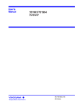
Programming of codes can be done only once or can
be done any number of times after the EEPROM
RESET procedure. It depends on setting of [C1]
parameter. The following scheme illustrates how code
programming is performed:
PREALARM–
PREALARM– DURESS FUNCTION
FUNCTION
This function activates the PREALARM transistor
output when three consecutive attempts of entering
access codes fail or command 2 is used. The
PREALARM output automatically switches off after 60
seconds. A short acoustic signal sequence is
generated in addition to activation of the PREALARM
output when three consecutive attempts of entering
access codes fail. The PREALARM-DURESS function
is usually utilised for signalling keypad manipulation or
silent alarm generation due to entering the main code
under duress (command 2).
BELL FUNCTION
This function activates the PREALARM output after the
[#] key is pressed down longer then 0.5 seconds. The
output remains in the active state for as long as the [#]
key is held pressed down. After the [#] key is released
the output remains active for two seconds after which it
switches off. This function is usually used for calling
security or signalling the intention to enter the
premises.
LOCK’S CODES
[KG] Main code
This code can consist of 2 to 6 digits. It is used to
control all of the lock’s outputs as well as for
programming.
[KS] Vault code
This is a four-digit code which can be enabled or
disabled during the lock configuration procedure. If
this code is enabled the stable mode output will
only switch from OFF to ON after the main code
[KG] is entered followed by the vault code [KS].
[KD] Door code
This is a four-digit code which is only used for
controlling the output operating in the pulse mode. It is
used for switching on the pulse output for a time
defined by [C4C5].
[KZ] Locking code
This is a four-digit code which is only used for
controlling the output operating in the stable mode. It
causes the stable mode output to switch from ON to
OFF. Use of this code requires command 4 to be
entered before.
[*] [PREVIOUS KG] [#] [NEW KG] [#] [NEW KG] [#]
{ [#] } [NEW KD] [#] { [#] } [NEW KZ] [#]
IMPORTANT !
Pressing [#] in places specified by { } enables the user
to exit the programming function earlier while saving
all previously programmed settings. If the use of the
[KS] code is enabled (parameter [C2]=[1]), it can be
programmed according to the following scheme:
[*][PREVIOUS KS][#][NEW KS][#][NEW KS][#]
LOCK’S COMMANDS
The electronic keypad lock uses acoustic signals to
indicate three phases of command entry:
- a single short signal (*) indicates that a key has been
pressed
- two series of two signals (** **) indicate that part of a
command was entered correctly and that the device
awaits further entry
- three acoustic signals (***) indicate that the entire
command was entered successfully
- a single long signal ( - ), lasting for about 2s,
indicates an error
Command 1 [KG][#]
Switches the output operating in stable mode to an
opposite state of that before the command was
initiated.
Command 2 [KG][N][#]
Acts in the same manner as command 1 and switch on
signalling the PREALARM-DURESS function.
Command 3 [KG][*][#]
Switches on the output operating in pulse mode for a
time defined by the calibrated delay. It works identical
to command 6.
Command 4 [KG][*][*][#]
Allows for a single use of command 7.
Command 5 [KG][*][*][*][#][H][M][M][#]
Switches the output operating in stable mode to the
opposite state after H-hours and MM-minutes. The H
parameter can be from 0 to 9 and the MM parameter
from 00 to 59. If a new command 5 is entered during
an already initiated command 5 the new settings of H
and MM will take place of the previous ones. If
command 1 is entered during an already initiated
command 5 it will override command 5 and the lock will
immediately switch the stable output. If the lock is
currently processing command 5 and the countdown is
grater then 15 minutes the device generates a short
acoustic signal every minute. If this time is shorter then
15 minutes the lock will generate a short acoustic
signal every 2 seconds. This is used to indicate that the
switching of stable output will take place.
Command 6 [KD][#]
Switches ON the output operating in pulse mode for a
time of [C4C5] seconds being the calibrated delay.
Command 7 [KZ][#]
Switches the output operating in stable mode from ON
to OFF. This only takes place if the main code
(command 4) permits this. Command 4 must be
entered every time before command 7 is to be use.
Command 8 [KG][#][KS][#]
If the use of the [KS] code is enabled (parameter
[C2]=[1]) then stable output can only be switched from
OFF to ON after this command is initiated. The [KS]
code must be entered within 30 seconds from the entry
of the main code [KG].
Command 9
[#]
Usually this key is used to end code entry. Additionally
if [C3]=[1] was set during configuration and [#] is held
down the PREALARM output is activated. After the [#]
key is released the output remains active for 2 seconds
after which it switches off. This key can be used for
calling security or signalling the intention to enter the
premises.
CONFIGURATION – EEPROM RESET
change the code without a need for EEPROM RESET.
[C2]
Enables the use of [KS] code.
[C2]=[0] ; disables the use of the [KS] code
[C2]=[1] ; enables the use of the [KS] code
[C3]
Defines the function of the PREALARM
transistor output.
[C3]=[0]; the output signalling the PREALARMDURESS function
[C3]=[1] ; the output signalling the BELL
function
[C4C5] Defines the calibrated delay on the stable
output (00..99 seconds)
After the [C5] digit is entered the lock is configured and
changes are stored in memory. After configuration the
device automatically sets the lock’s codes to the
following values:
[KG]
[KS]
[KD]
[KZ]
-
[1234]
[9999]
[1111]
[2222]
If en error is made during the entry of [C1..C5] digits
the device signals it by sounding the error beep. All
previous settings are cancelled and the lock restart
configuration procedure. The user must re-enter digits
[C1...C5].
Example:
In order to configure the electronic keypad lock the
EEPROM reset procedure should be carried out first.
Then a sequence of five digits [C1..C5] should be
entered according to the steps below:
The installer has RESET the EEPROM and entered the
following digit sequence [1][0][1][2][5]. This has the
following meaning:
-
-
-
Turn off the power supply.
Switch the jumper from the NORMAL position to
EEPROM RESET.
Turn on the power supply.
Wait few second, the device will generate sound
periodically,
Switch the jumper from the EEPROM RESET
position to NORMAL.
Wait until two sounds,
Enter five digits [C1..C5] to configure the lock.
Wait for the device to sound three beeps, which
will acknowledge the new configuration.
The unit is ready for operation.
Configuration parameters definition:
[C1]
Enables multiple code reprogramming
[C1]=[0] ; codes can only be set once
[C1]=[1] ; codes can be set any number of
times
IMPORTANT !
If multiple code programming is disabled ([C1]=[0]) –
the device will only permit a single entry of the selected
code. Once programmed, it will not be possible to
-
codes can be set any number of times [C1]=[1]
the use of the vault code [KS] is disabled [C2]=[0]
the PREALARM output performs the BELL function
when the [#] key is held pressed down [C3]=[1]
the calibrated delay on the stable output is set to
25 seconds [C4C5]=[25]
TECHNICAL DATA
Power supply voltage:
11..15 Vdc
Current consumption:
Typical 15mA
Current consumption with
activated relay output:
Max. 60mA
Operating environment
temperature range:
20..+50 degrees C
Relay output load:
Max. 1.5A 24Vdc/ac
PREALARM and AUX output
load:
Max. 150mA
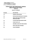
Output control modes
Jumper
AUX
output
Relay
output
STABLE
STABLE
J1 J2 J3 J4 J5 J6
Function
STABLE
PULSE
PULSE
STABLE
PULSE
PULSE
Unit RESET
Normal operation
Jumper
Relay contact selection
Contacts normally open (NO)
NO NC
Contacts normally closed(NC)
NO NC
Jumpers position
SL1000A
J6 J5 J4 J3 J2 J1
J1 J2 J3 J4 J5 J6
SL1000C, SL1000H
+12V
max. 150 mA
+12V
+12V
Max. 150 mA
SL1000B
1kÙ
NO
NC
Var 24V
+12V
10 Ù
1
COM
2
NO
NC
3
PRE
AL.
10 Ù
4
AUX
5
6
7
LED
+
-
12VDC
SL1000A, SL1000C, SL1000H
8
9
TAMPER