1
User’s
Manual
SL1000
Input Module
IM 720120-51E
1st Edition
Thank you for purchasing the SL1000 High-Speed Data Acquisition Unit. This user’
s manual explains the functions and operating procedures of the SL1000 Acquisition
Software. To ensure correct use, please read this manual thoroughly before beginning
operation.
After reading the manual, keep it in a convenient location for quick reference whenever a
question arises during operation. The following manuals, including this one, are provided
as manuals for the SL1000. Please read all of them.
This user's manual contains specifications of the measurement modules that can be
used on the SL1000 unit.
For information such as setup procedures, see the Data Acquisition Software User's
Manual.
Notes
• The contents of this manual are subject to change without prior notice as a result of
continuing improvements to the instrument’s performance and functions. The figures
given in this manual may differ from those that actually appear on your screen.
• Every effort has been made in the preparation of this manual to ensure the accuracy
of its contents. However, should you have any questions or find any errors, please
contact your nearest YOKOGAWA dealer.
• Copying or reproducing all or any part of the contents of this manual without
YOKOGAWA’s permission is strictly prohibited.
Revisions
• 1st Edition:December 2007
1st Edition : December 2007(YK)
All Rights Reserved, Copyright © 2007 Yokogawa Electric Corporation
IM 720120-51E
Contents
1
2
3
4
5
6
7
8
9
10
11
12
13
14
High-Speed 10 MS/s, 12-Bit Isolation Module (701250) Specifications......................................... 3
High-Speed High-Resolution 1 MS/s, 16-Bit Isolation Module (701251) Specifications......... 5
High-Speed 10 MS/s, 12-Bit Non-Isolation Module (701255) Specifications............................... 7
High-Voltage 100 kS/s, 16-Bit Isolation Module (with RMS) (701260) Specifications.............. 9
Universal (Voltage/Temp.) Module (701261) /Universal (Voltage/Temp.) Module (with AAF) (701262) Specifications.............................................................................................................11
Temperature, High Precision Voltage Isolation Module (701265) Specifications....................13
Strain Module (NDIS) (701270) Specifications.......................................................................................15
Strain Module (DSUB, Shunt-Cal) (701271) Specifications................................................................17
Acceleration/Voltage Module (with AAF) (701275) Specifications...............................................19
Frequency Module (701280) Specifications............................................................................................21
High-Speed 100 MS/s, 12-Bit Isolation Module (720210) Specifications....................................25
Basic Defining Equation of Strain................................................................................................................27
Shunt Calibration of the Strain Module....................................................................................................28
Measurement Principles (Measurement Method and Update Rate) of the Frequency
Module...................................................................................................................................................................32
IM 720120-51E
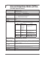
1
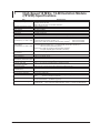
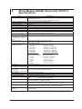
High-Speed 10 MS/s, 12-Bit Isolation Module
(701250) Specifications
Item
Standard operating conditions
Effective measurement range
Number of input channels
Input coupling
Maximum sample rate
Input format
Frequency characteristics1
Voltage-axis range setting
Maximum input voltage
(at a frequency of 1 kHz or less)
Maximum allowable common
mode voltage
(at a frequency of 1 kHz or less)
Vertical (voltage) axis accuracy
DC accuracy1
Input connector
Input impedance
–3 dB point when AC coupled
low frequency attenuation point
Common mode rejection ratio
Residual noise level
(Input section shorted)
Withstand voltage
Allowable transient surge voltage
(instantaneous)
Insulation resistance
A/D conversion resolution
Temperature coefficient
Bandwidth limit
Probe attenuation setting
IM 720120-51E
Specifications
Temperature: 23° C±5° C
Humidity: 55%±10% RH
After a 30-minute warm-up and after calibration
Twice of setting range
2
AC, DC, and GND
10 MS/s
Isolated unbalanced
(–3 dB point when sine wave of amplitude 60 % of range is input) DC to 3 MHz
50 mV to 200 V range (1-2-5 steps)
Combined with the 700929(10:1)2
600 V (DC+ACpeak)
Combined with the 701901+701954 (1:1)4
250 V (DC+ACpeak)
Direct input or cable not complying with the safety standard6 250 V (DC+ACpeak)
Working voltage of safety standard
Combined with the 700929 (10:1)3 or combined with the 701901+701954 (1:1)5
400 Vrms (CAT I) 300 Vrms (CAT II)
Direct input or cable not complying with the safety standard7
42 V (DC+ACpeak) (CAT I and CAT II, 30 Vrms)
50 mV to 200 V range:
±(0.5% of range)
BNC connector (isolated type)
1 MΩ ± 1%, approx. 35 pF
10 Hz or less (1 Hz or less when using the 700929)
80 dB (50/60 Hz) or more (typical8)
±400 µ V or ±0.6% of range whichever is greater (Typical8)
1500 Vrms for 1 minute (across each terminal and earth) (60 Hz)
±2100 Vpeak (across each input terminal and earth)
500 VDC, 10 MΩ or more (across each input terminal and earth)
12 bit (1500 LSB/range)
Zero point: 50 mV to 200 V range: ±(0.05% of range)/° C(Typical8)
Gain: ±(0.02% of range)/° C(Typical8)
Select from OFF, 500 kHz, 50 kHz, 5 kHz, and 500 Hz
Cut-off characteristics: –18 dB/OCT (Typical8)
Voltage probe: 1:1, 10:1, 100:1, 1000:1
Current probe: 10 A:1 V (for the 700937/701933), 100 A: 1 V (for the 701930/701931)
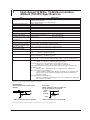
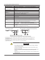
1 High-Speed 10 MS/s, 12-Bit Isolation Module (701250) Specifications
Item
Compatible probes/cables
Specifications
Voltage probe (10:1 safety probe): Recommended
700929 (10:1 safety probe).20 to 45 pF: For measuring 600 Vpeak or less
Current probe (power can be supplied from the SL1000 Unit. Option)
700937 (15 A), 701930 (150 A), 701931 (500 A), 701933 (30 A)
High voltage differential probe (connect the GND cable provided with the probe to the
SL1000 Unit case)
700924 (1000:1, 100:1/1400 Vpeak): For measuring 1400 Vpeak or less
Connection cable (for high voltage 1:1)
701901 (isolated type BNC-safety alligator clip adapter ×2: For measuring 250
Vpeak or less), 701954 (alligator clip (dolphin type) red/black 2-piece set) is
required separately
Connection cable (for low voltage 1:1)
366926 (non-isolated type BNC-alligator clip ×2: For measuring low voltage less
than or equal to 42 Vpeak)
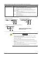
1. Value measured under standard operating conditions.
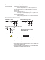
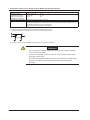
Combined with the 700929
Combined with the 701901+701954
H
H
700929
701901
2.
L
701954
4.
L
3.
5.
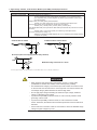
Direct input (cable not complying with the safety standard)
H
BNC
6.
7.
L
Withstand voltage: 1500 Vrms for 1 minute
Allowable transient surge voltage: 2100 Vpeak
(between earth and input)
8. The typical value is a representative or standard value. It is not strictly warranted.
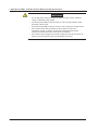
WARRNING
• Do not apply input voltage exceeding the maximum input voltage, withstand
voltage, or allowable surge voltage.
• To prevent the possibility of electric shock, be sure to furnish protective earth
grounding of the SL1000.
• To prevent the possibility of electric shock, be sure to fasten the module
screws. Otherwise, the electrical and mechanical protection functions will not be
activated.
• Avoid continuous connection under an environment in which the allowable surge
voltage or higher voltage may occur.
• To prevent the possibility of electric shock, be sure to connect the GND lead of
the differential probe (700924/700925) to the SL1000.
IM 720120-51E
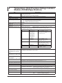
2
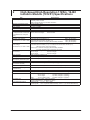
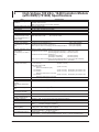
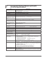
High-Speed High-Resolution 1 MS/s, 16-Bit
Isolation Module (701251) Specifications
Item
Standard operating conditions
Effective measurement range
Number of input channels
Input coupling
Maximum sample rate
Input format
Frequency characteristics1
(–3 dB point when a sine wave
of amplitude 60 % of range is
input)
Voltage-axis range setting
Maximum input voltage
(at a frequency of 1 kHz or less)
Maximum allowable common
mode voltage
(at a frequency of 1 kHz or less)
Vertical (voltage) axis accuracy
DC accuracy1
Input connector
Input impedance
–3 dB point when AC coupled
low frequency attenuation point
Common mode rejection ratio
Residual noise level
(Input section shorted)
Withstand voltage
Allowable transient surge voltage
(instantaneous)
Insulation resistance
A/D conversion resolution
Temperature coefficient
Bandwidth limit
Probe attenuation setting
IM 720120-51E
Specifications
Temperature: 23° C±5° C
Humidity: 55%±10% RH
After a 30-minute warm-up and after calibration
Twice of setting range
2
AC, DC, and GND
1 MS/s
Isolated unbalanced
50 mV to 200 V range:
DC to 300 kHz
20 mV and 10 mV range:
DC to 200 kHz
10 mV to 200 V range (1-2-5 steps)
Combined with the 700929(10:1)2
600 V (DC+ACpeak)
Combined with the 701901+701954 (1:1)4
140 V (DC+ACpeak)
Direct input or cable not complying with the safety standard6 140 V (DC+ACpeak)
Working voltage of safety standard
Combined with the 700929 (10:1)3 or combined with the 701901+701954 (1:1)5
400 Vrms (CAT I), 300 Vrms (CAT II)
Direct input or cable not complying with the safety standard7
42 V (DC+ACpeak) (CAT I and CAT II, 30 Vrms)
50 mV to 200V range:
±(0.25% of range)
20 mV range:
±(0.3% of range)
10 mV range:
±(0.5% of range)
BNC connector (isolated type)
1 MΩ ± 1%, approx. 35 pF
10 Hz or less (1 Hz or less when using the 700929)
80 dB (50/60 Hz) or more (typical8)
±100 µ V or ±0.1% of range whichever is greater (Typical8)
1500 Vrms for 1 minute (across each terminal and earth) (60 Hz)
±2100 Vpeak (across each input terminal and earth)
500 VDC, 10 MΩ or more (across each input terminal and earth)
16 bit (24000 LSB/range)
Zero point: 50 mV to 200 V range:
±(0.02% of range)/° C(Typical8)
20 mV range:
±(0.05% of range)/° C(Typical8)
10 mV range:
±(0.10% of range)/° C(Typical8)
Gain: 10 mV to 200 V range:
±(0.02% of range)/° C(Typical8)
Select from OFF, 40 kHz, 4 kHz, and 400 Hz
Cut-off characteristics: –12 dB/OCT (Typical8)
Voltage probe: 1:1, 10:1, 100:1, 1000:1
Current probe: 10 A:1 V (for the 700937/701933), 100 A: 1 V (for the 701930/701931)
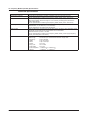
2 High-Speed High-Resolution 1 MS/s, 16-Bit Isolation Module (701251) Specifications
Item
Compatible probes/cables
Specifications
Voltage probe (10:1 safety probe): Recommended
700929 (10:1 safety probe).20 to 45 pF: For measuring 600 Vpeak or less
Current probe (power can be supplied from the SL1000 Unit. Option)
700937 (15 A), 701930 (150 A), 701931 (500 A), 701933 (30 A)
High voltage differential probe (connect the GND cable provided with the probe to the
SL1000 Unit case)
700924 (1000:1, 100:1/1400 Vpeak): For measuring 1400 Vpeak or less
Connection cable (for high voltage 1:1)
701901 (isolated type BNC-safety alligator clip adapter ×2: For measuring 250
Vpeak or less), 701954 (alligator clip (dolphin type) red/black 2-piece set) is
required separately
Connection cable (for low voltage 1:1)
366926 (non-isolated type BNC-alligator clip ×2: For measuring low voltage less
than or equal to 42 Vpeak)
1. Value measured under standard operating conditions.
Combined with the 700929
Combined with the 701901+701954
H
H
700929
701901
2.
L
701954
4.
L
3.
5.
Direct input (cable not complying with the safety standard)
H
BNC
6.
7.
L
Withstand voltage: 1500 Vrms for 1 minute
Allowable transient surge voltage: 2100 Vpeak
(between earth and input)
8. The typical value is a representative or standard value. It is not strictly warranted.
WARRNING
• Do not apply input voltage exceeding the maximum input voltage, withstand
voltage, or allowable surge voltage.
• To prevent the possibility of electric shock, be sure to furnish protective earth
grounding of the SL1000.
• To prevent the possibility of electric shock, be sure to fasten the module
screws. Otherwise, the electrical and mechanical protection functions will not be
activated.
• Avoid continuous connection under an environment in which the allowable surge
voltage or higher voltage may occur.
• To prevent the possibility of electric shock, be sure to connect the GND lead of
the differential probe (700924/700925) to the SL1000.
IM 720120-51E
3
High-Speed 10 MS/s, 12-Bit Non-Isolation
Module (701255) Specifications
Item
Standard operating conditions
Effective measurement range
Number of input channels
Input coupling
Maximum sample rate
Input format
Frequency characteristics1
Voltage-axis range setting
Maximum input voltage
(at a frequency of 1 kHz or less)
Vertical (voltage) axis accuracy
DC accuracy1
Input connector
Input impedance
–3 dB point when AC coupled
low frequency attenuation point
Residual noise level
(Input section shorted)
A/D conversion resolution
Temperature coefficient
Bandwidth limit
Probe attenuation setting
Compatible probes/cables
Specifications
Temperature: 23° C±5° C
Humidity: 55%±10% RH
After a 30-minute warm-up and after calibration
Twice of setting range
2
AC, DC, and GND
10 MS/s
Non-isolated, unbalanced
(–3 dB point when sine wave of amplitude 60 % of range is input) DC to 3 MHz
50 mV to 200 V range (1-2-5 steps)
Combined with the 701940(10:1)2
600 V (DC+ACpeak)
Direct input(1:1)3
250 V (DC+ACpeak)
50 mV to 200 V range:
±(0.5% of range)
BNC connector (metallic type)
1 MΩ ± 1%, approx. 35 pF
10 Hz or less (1 Hz or less when using the 701940)
±400 µ V or ±0.6% of range whichever is greater (Typical4)
12 bit (1500 LSB/range)
Zero point: 50 mV to 200 V range:
±(0.05% of range)/° C(Typical4)
Gain: ±(0.02% of range)/° C(Typical4)
Select from OFF, 500 kHz, 50 kHz, 5 kHz, and 5400 Hz
Cut-off characteristics: –18 dB/OCT (Typical4)
Voltage probe: 1:1, 10:1, 100:1, 1000:1
Current probe: 10 A:1 V (for the 700937/701933), 100 A: 1 V (for the 701930/701931)
Voltage probe (10:1 safety probe): Recommended
701940, 17 to 46 pF: For measuring 600 Vpeak or less
Current probe (power can be supplied from the SL1000 Unit. Option)
700937 (15 A), 701930 (150 A), 701931 (500 A), 701933 (30 A)
High voltage differential probe (connect the GND cable provided with the probe to the
SL1000 Unit case)
700924 (1000:1, 100:1/1400 Vpeak): For measuring 1400 Vpeak or less
Connection cable (for high voltage 1:1)
701901 (isolated type BNC-safety alligator clip adapter ×2: For measuring 250
Vpeak or less), 701954 (alligator clip (dolphin type) red/black 2-piece set) is
required separately
Connection cable (for low voltage 1:1)
366926 (non-isolated type BNC-alligator clip ×2: For measuring low voltage less
than or equal to 42 Vpeak)
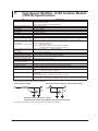
1. Value measured under standard operating conditions.
Recommended:
Combined with the 10:1 passive probe
(701940)
H
2.
L
Direct input
(When a cable that does not comply with
the safety standard is connected)
701255
Input
terminal
GND
H
3.
L
GND
Earth
GND is connected to the case potential.
GND is connected to the case potential.
8. The typical value is a representative or standard value. It is not strictly warranted.
IM 720120-51E
3 High-Speed 10 MS/s, 12-Bit Non-Isolation Module (701255) Specifications
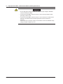
WARRNING
• Do not apply input voltage exceeding the maximum input voltage, withstand
voltage, or allowable surge voltage.
• To prevent the possibility of electric shock, be sure to furnish protective earth
grounding of the SL1000.
• To prevent the possibility of electric shock, be sure to fasten the module screws.
• The module screws must be fastened for the module to function as a
nonisolation module. In addition, all electrical and mechanical protection
functions are activated only when the screws are fastened.
• The maximum input voltage of the module is valid only when all the screws are
fastened, and the protection path of the metal BNC is secured.
IM 720120-51E
4
High-Voltage 100 kS/s, 16-Bit Isolation Module
(with RMS) (701260) Specifications
Item
Standard operating
conditions
Specifications
Temperature: 23° C±5° C
Humidity: 55%±10% RH
After a 30-minute warm-up and after calibration
Effective measurement range Twice of setting range
Number of input channels
2
Input coupling
AC, DC, GND, AC-RMS, and DC-RMS
Maximum sample rate
100 kS/s
Input format
Isolated unbalanced
Frequency characteristics1
Waveform observation mode: DC to 40 kHz
(–3 dB point when a sine
RMS observation mode:
DC, 40 Hz to 10 kHz
wave of amplitude 60 % of
range is input)
Voltage-axis range setting
200 mV to 2 kV range (1-2-5 steps)
Maximum input voltage
Combined with the 700929(10:1)2
(at a frequency of 1 kHz or
Combined with the 701901+701954 (1:1)5
less)
Direct input or cable not complying with the safety standard8
Maximum allowable common
mode voltage
(at a frequency of 1 kHz or
less)
Vertical (voltage) axis
accuracy DC accuracy1
Input connector
Input impedance
–3 dB point when AC
coupled
low frequency attenuation
point
Common mode rejection
ratio
Residual noise level
(Input section shorted)
Withstand voltage
Allowable transient surge
voltage (instantaneous)
Insulation resistance
A/D conversion resolution
Temperature coefficient
Response time (only when
observing RMS)
Bandwidth limit
Probe attenuation setting
IM 720120-51E
1000 V (DC+ACpeak)
850 V (DC+ACpeak)
850 V (DC+ACpeak)
Working voltage of safety standard
Combined with the 700929 (across probe tip H and earth3): 1000 Vrms (CAT II)
(across probe tip L and earth4): 400 Vrms (CAT II)
Combined with the 701901+701954 (1:1)5
(across tip H and earth6):
700 Vrms (CAT II)
(across tip L and earth7): 400 Vrms (CAT II)
Direct input or cable not complying with the safety standard9:30 Vrms (42 VDC+ACpeak)
(across the input terminal, H or L, and earth)
Waveform observation mode
DC accuracy
±(0.25% of 10 div)
RMS observation mode
DC accuracy
±(1.0% of 10 div)
(when a sine wave is input)
AC accuracy ±(1.5% of 10 div) At frequency of 40 Hz to 1 kH
AC accuracy ±(2.0% of 10 div) At frequency of 40 Hz to 1 kH
(when the crest factor is 2 or less)
AC accuracy ±(3.0% of 10 div) At frequency of 40 Hz to 1 kH
(when the crest factor is 3 or less)
BNC connector (isolated type)
1 MΩ ± 1%, approx. 35 pF
1 Hz or less (0.1 Hz or less when using the 700929)
80 dB (50/60 Hz) or more (typical10)
±1 mV or ±0.2% of range whichever is greater (Typical10)
3700 Vrms for 1 minute (across each terminal and earth) (60 Hz)
±5200 Vpeak (across each input terminal and earth)
500 VDC, 10 MΩ or more (across each input terminal and earth)
16 bit (24000 LSB/range)
Zero point: ±(0.02% of range)/° C(Typical10)
Gain: ±(0.02% of range)/° C(Typical10)
Rising (0 to 90% of range): 100 ms (typical10)
Falling (100 to 10% of range):250 ms (typical10)
Select from OFF, 10 kHz,1 kHz, and 100 Hz
Cut-off characteristics: –12 dB/OCT (Typical10)
Voltage probe: 1:1, 10:1, 100:1, 1000:1
Current probe: 10 A:1 V (for the 700937/701933), 100 A: 1 V (for the 701930/701931)
4 High-Voltage 100 kS/s, 16-Bit Isolation Module (with RMS) (701260) Specifications
Item
Compatible probes/cables
Specifications
Connection cable (for high voltage 1:1)
701901 (isolated type BNC-safety alligator clip adapter ×2: For measuring 850 V
(DC+ACpeak)or less), 701954 (alligator clip (dolphin type) red/black 2-piece set) is
required separately
Voltage probe (10:1 safety probe): Recommended
700929 (10:1 safety probe).20 to 45 pF: For measuring 600 Vpeak or less
Current probe (power can be supplied from the SL1000 Unit. Option)
700937 (15 A), 701930 (150 A), 701931 (500 A), 701933 (30 A)
High voltage differential probe (connect the GND cable provided with the probe to the SL1000
Unit case)
700924 (1000:1, 100:1/1400 Vpeak): For measuring 1400 Vpeak or less
Connection cable (for low voltage 1:1)
366926 (non-isolated type BNC-alligator clip ×2: For measuring low voltage less than
or equal to 42 Vpeak)
1. Value measured under standard operating conditions.
Combined with the 700929
Combined with the 701901+701954
H
H
700929
701901
2.
3.
701954
L
5.
6.
L
7.
4.
Direct input (cable not complying with the safety standard)
H
BNC
8.
9.
L
Withstand voltage: 3700 Vrms for 1 minute
10. The typical value is a representative or standard value. It is not strictly warranted.
WARRNING
• When applying high voltage using this module, use the 1:1 safety cable
(combination of 701901 and 701954) or the isolated probe (700929).
• The Measurement Category of the direct input of this module is 400 Vrms-CATII
on the low side and 700 Vrms-CAT II on the high side. Use caution because the
overvoltage category differs between the low and high sides.
• Do not apply input voltage exceeding the maximum input voltage, withstand
voltage, or allowable surge voltage.
• To prevent the possibility of electric shock, be sure to furnish protective earth
grounding of the SL1000.
• To prevent the possibility of electric shock, be sure to fasten the module
screws. Otherwise, the electrical and mechanical protection functions will not be
activated.
• Avoid continuous connection under an environment in which the allowable surge
voltage or higher voltage may occur.
10
IM 720120-51E
5
Universal (Voltage/Temp.) Module (701261) /
Universal (Voltage/Temp.) Module (with AAF)
(701262) Specifications
Item
Standard operating conditions
Specifications
Temperature: 23° C±5° C
Humidity: 55%±10% RH
After a 30-minute warm-up and after calibration
Function
Temperature (thermocouple) or voltage measurement (switchable)
Effective measurement range
Voltage measurement:
Twice of setting range
Number of input channels
2
Input coupling
TC, DC, AC, and GND
TC: Temperature (thermocouple) measurement
DC: Voltage measurement (DC coupling)
AC: Voltage measurement (AC coupling)
Voltage measurement maximum 100 kS/s
sample rate
Temperature measurement data 500Hz
update rate
Input format
Isolated unbalanced
Measurement range/accuracy1
[Voltage measurement] Voltage sensitivity: 50 mV to 200 V range (1-2-5 steps)
Voltage accuracy: ±(0.25% of range)
[Temperature measurement]2
Type
Frequency characteristics1
(–3 dB point when a sine wave
of amplitude 60 % of range is
input)
Maximum input voltage4
(at a frequency of 1 kHz or less)
Maximum allowable common
mode voltage5
(at a frequency of 1 kHz or less)
Vertical resolution
–3 dB point when AC coupled
low frequency attenuation point
Input connector
Input impedance
IM 720120-51E
K
E
J
T
L
U
N
R
S
Measurement Range
−200 to 1300° C
−200 to 800° C
−200 to 1100° C
−200 to 400° C
−200 to 900° C
−200 to 400° C
0 to 1300° C
0 to 1700° C
0 to 1700° C
B
0 to 1800° C
W
Au7Fe3
0 to 2300° C
0 to 300K
Accuracy
±(0.1% of reading + 1.5° C)
Except ±(0.2% of reading + 1.5° C)
for –200° C to 0° C
±(0.1% of reading + 3° C)
Except, 0 to 200° C: ±8° C
200 to 800° C: ±5° C
±(0.1% of reading + 2° C)
Except, 400 to 700° C: ±8° C
Effective range is 400 to 1800° C
±(0.1% of reading + 3° C)
0 to 50K:
±4K
50 to 300K: ±2.5K
[Voltage measurement]
DC to 40 kHz
[Temperature measurement] DC to 100 Hz
Both temperature and voltage input: 42 V (DC + ACpeak) (as a value that meets the safety
standard)
150 V (DC + ACpeak) (maximum allowable voltage, as a value that does not damage the
instrument when applied)
Both temperature and voltage input: 42 V (DC+ACpeak) (CAT I and CAT II, 30 Vrms)
[Voltage measurement] During voltage input: 24000 LSB/range
[Temperature measurement] When measuring temperature: 0.1° C
[Voltage measurement]
0.5 Hz or less
Binding post
Approx. 1 MΩ
11
5 Universal (Voltage/Temp.) Module (701261)/Universal (Voltage/Temp.) Module (with AAF) (701262) Specifications
Item
Common mode rejection [Voltage measurement]
ratio
[Temperature measurement]
Residual noise level
(Input section shorted)
A/D conversion
resolution
Temperature coefficient
[Voltage measurement]:
Specifications
80 dB (50/60 Hz) or more (typical6)
120 dB or more (50/60 Hz, with 2-Hz filter ON, signal source
resistance of 500 Ω or less) (typical6)
±100 µ V or ±0.1% of range, whichever is greater (typical6)
[Voltage measurement]
16 bits (24000 LSB/range)
[Voltage measurement]
Zero point: ±(0.01% of range)/° C (typical6)
Gain:
±(0.02% of range)/° C (typical6)
K, E, J, T, L, U, N:
±1° C
R, S, B, W:
±1.5° C
Au7Fe:
±1K
Reference junction
compensation accuracy
(when the input terminal
temperature is balanced)
Bandwidth limit
[Temperature measurement] (Digital filter + analog filter)
Select from OFF, 30 Hz, 8 Hz, and 2 Hz + 150 Hz secondary
analog filter
[Voltage measurement]
Select from OFF, AUTO, 4 kHz, 400 Hz, or 40 Hz.
Cutoff characteristics: –12 dB/OCT (typical6, setting other than
AUTO)
Cutoff frequency (fc) when set to AUTO (701262 only)
Sample Rate
100 kS/s or higher
100 S/s to 50 kS/s
50 S/s or less
Cutoff Frequency (fc)
40kHz
40% of the sample rate
20Hz
Cutoff characteristics for AUTO: –65 dB at 2 × fc (typical6)
Table of cutoff frequency When the filter is set to Auto, the anti-aliasing filter and low-pass filter are automatically set
characteristics of the
according to the sample rate.
anti-aliasing filter (AAF)
Sample Rate
AAF
Low-Pass Filter
100kS/s
50kS/s
20kS/s
10kS/s
5kS/s
2kS/s
1kS/s
500S/s
200S/s
100S/s
50S/s
20S/s to 5S/s
2S/s or less
Ext sample
40kHz
20kHz
8kHz
4kHz
2kHz
800Hz
400Hz
200Hz
80Hz
40Hz
20Hz
20Hz
20Hz
40kHz
OFF
OFF
OFF
4kHz
4kHz
4kHz
400Hz
400Hz
400Hz
40Hz
40Hz
40Hz
40Hz
OFF
1. Value measured under standard operating conditions (section 19.11).
2. Does not include the reference junction temperature compensation accuracy.
3. This module supports Au7Fe with 0.07% metal content with respect to gold.
H
4.
L
5.
6. Typical value represents a typical or average value. It is not strictly warranted.
WARRNING
• Do not apply input voltage exceeding the maximum input voltage or allowable
common mode input voltage.
• To prevent the possibility of electric shock, be sure to furnish protective earth
grounding of the DL750/DL750P.
• To prevent the possibility of electric shock, be sure to fasten the module screws.
Otherwise, the electrical and mechanical protection functions will not be
activated.
12
IM 720120-51E
6
Temperature, High Precision Voltage Isolation
Module (701265) Specifications
Item
Standard operating conditions
Specifications
Temperature: 23° C±5° C
Humidity: 55%±10% RH
After a 30-minute warm-up and after calibration
Function
Temperature (thermocouple) or voltage measurement (switchable)
Effective measurement range
Voltage measurement:
Twice of setting range
Number of input channels
2
Input coupling
TC, DC, and GND
TC: Temperature (thermocouple) measurement
DC: Voltage measurement (DC coupling)
Voltage measurement maximum 100 kS/s
sample rate
Temperature measurement data 500Hz
update rate
Measurement range/accuracy1
[Voltage measurement] Voltage sensitivity: 1 mV to 100 V range (1-2-5 steps)
Voltage accuracy: ±(0.08% of range + 2µ V)
[Temperature measurement]2
Type
Frequency characteristics1
(–3 dB point when a sine wave
of amplitude 60 % of range is
input)
Maximum input voltage4
(at a frequency of 1 kHz or less)
Maximum allowable common
mode voltage5
(at a frequency of 1 kHz or less)
Vertical resolution
–3 dB point when AC coupled
low frequency attenuation point
Input connector
Input impedance
Common mode rejection ratio
Residual noise level
(Input section shorted)
A/D conversion resolution
Temperature coefficient
IM 720120-51E
K
E
J
T
L
U
N
R
S
Measurement Range
−200 to 1300° C
−200 to 800° C
−200 to 1100° C
−200 to 400° C
−200 to 900° C
−200 to 400° C
0 to 1300° C
0 to 1700° C
0 to 1700° C
B
0 to 1800° C
W
Au7Fe3
0 to 2300° C
0 to 300K
Accuracy
±(0.1% of reading + 1.5° C)
Except ±(0.2% of reading + 1.5° C)
for –200° C to 0° C
±(0.1% of reading + 3° C)
Except, 0 to 200° C: ±8° C
200 to 800° C: ±5° C
±(0.1% of reading + 2° C)
Except, 400 to 700° C: ±8° C
Effective range is 400 to 1800° C
±(0.1% of reading + 3° C)
0 to 50K:
±4K
50 to 300K: ±2.5K
[Voltage measurement]
DC to 100 Hz
[Temperature measurement] DC to 100 Hz
Both temperature and voltage input: 42 V (DC + ACpeak)
Both temperature and voltage input: 42 V (DC+ACpeak) (CAT I and CAT II, 30 Vrms)
[Voltage measurement] During voltage input: 2400 LSB/div
[Temperature measurement] When measuring temperature: 0.1° C
[Voltage measurement]
0.5 Hz or less
Binding post
Approx. 1 MΩ
[Voltage measurement]
[Temperature measurement]
[Voltage measurement]:
80 dB (50/60 Hz) or more (typical6)
120 dB or more (50/60 Hz, with 2-Hz filter ON, signal
source resistance of 500 Ω or less) (typical6)
±4 µ V or ±0.1% of range, whichever is greater (typical6)
[Voltage measurement]
[Voltage measurement]
16 bits (24000 LSB/range)
Zero point: ±(0.01% of range)/° C (typical6)
Gain:
±(0.02% of range)/° C (typical6)
13
6 Temperature, High Precision Voltage Isolation Module (701265) Specifications
Item
Reference junction
compensation accuracy
(when the input terminal
temperature is balanced)
Bandwidth limit (digital filter)
Input bias current
Specifications
K, E, J, T, L, U, N:
R, S, B, W:
Au7Fe:
±1° C
±1.5° C
±1K
Select from OFF, 30 Hz, 8 Hz, and 2 Hz
20 nA or less
The zero point appears to be offset when the input is open due to the effects of bias current on
this module. However, this is not a malfunction.
Connect the input to the object to be measured.
1. Value measured under standard operating conditions.
2. Does not include the reference junction temperature compensation accuracy.
3. This module supports Au7Fe with 0.07% metal content with respect to gold.
H
4.
L
5.
6. The typical value is a representative or standard value. It is not strictly warranted.
WARNING
• Do not apply input voltage exceeding the maximum input voltage or allowable
common mode input voltage.
• To prevent the possibility of electric shock, be sure to furnish protective earth
grounding of the SL1000.
• To prevent the possibility of electric shock, be sure to fasten the module screws.
Otherwise, the electrical and mechanical protection functions will not be
activated.
14
IM 720120-51E
7
Strain Module (NDIS) (701270) Specifications
Item
Standard operating conditions
Effective measurementrange
Number of input channels
Maximum sample rate
Input format
Auto balance type
Auto balance range
Bridge voltage
Gauge resistance
Gauge factor
Frequency characteristics1
(–3 dB point when a sine wave
of amplitude 60 % of range is
input)
mV/V range support
Measurement range (FS) and
measurement range
DC accuracy1
Maximum input voltage
(at a frequency of 1 kHz or less)
Maximum allowable common
mode voltage
(at a frequency of 1 kHz or less)
Input connector
Common mode rejection ratio
A/D conversion resolution
Temperature coe
Bandwidth limit
Function
Standard accessories
Compatible accessories (sold
separately)
IM 720120-51E
Specifications
Temperature: 23° C±5° C
Humidity: 55%±10% RH
After a 30-minute warm-up and after calibration and auto balance
–FS to +FS (set using upper and lower limits)
2
100 kS/s
DC bridge (auto balancing), balanced differential input, and isolated
Electronic auto balance
±10000 µ STR (1 gauge method)
Select from 2 V, 5 V, and 10 V.
120 Ω to 1000 Ω (bridge voltage: 2 V)
350 Ω to 1000 Ω (bridge voltage: 2 V, 5 V, and 10 V)
1.90 to 2.20 (set in 0.01 steps)
DC to 20 kHz
Supports the strain gauge transducer unit system.
mV/V range = 0.5×(µSTR range/1000)
When using STR range
Measurement Range (FS) Measurement Range
500µSTR
−500µSTR to +500µSTR
1000µSTR
−1000µSTR to +1000µSTR
2000µSTR
−2000µSTR to +2000µSTR
5000µSTR
−5000µSTR to +5000µSTR
10000µSTR
−10000µSTR to +10000µSTR
20000µSTR
−20000µSTR to +20000µSTR
When using mV/V range
Measurement Range (FS)
Measurement Range
0.25mv/V
−0.25mV/V to +0.25mV/V
0.5mV/V
−0.5mV/V to +0.5mV/V
1mV/V
−1mV/V to +1mV/V
2.5mV/V
−2.5mV/V to +2.5mV/V
5mV/V
−5mV/V to +5mV/V
10mV/V
−10mV/V to +10mV/V
±(0.5% of FS+5µSTR)
Between Input+ and Input– 10 V (DC+ACpeak)
Between each terminal and earth ground
42 V (DC+ACpeak) (CAT I and CAT II, 30 Vrms)
NDIS connector (Recommended by JSNDI (The Japanese Society for Non-destructive
Inspection)
80 dB (50/60 Hz) or more (Typical2 )
16 bit (48000 LSB/range: Upper = +FS, Lower = –FS)
Zero point:
±5µSTR/° C(Typical2)
Gain:
±(0.02% of FS)/° C (Typical2)
Select from OFF, 1 kHz, 100 Hz, and 10 Hz
Cutoff characteristics: –12 dB/OCT (Typical2)
mV/V support. Supports the strain gauge transducer unit system.
NDIS connector (for external connection: PRC03-12A10-7M10.5 by Tajimi) A1002JC: 2
pieces
Recommended bridge head 701955
(NDIS 120 Ω, enhanced shield version, comes with a 5-m cable)
Recommended bridge head 701956
(NDIS 350 Ω, enhanced shield version, comes with a 5-m cable))
15
7 Strain Module (NDIS) (701270) Specifications
Item
Specifications
• Highly sensitive measurements are made in the µ V level in strain measurements.
Therefore, take measures against noise at the strain sensor perimeter, bridge head,
and cable wiring.
• Depending on the noise environment, an error may result in the balance. Check the
influence before making measurements.
• The bridge head specified by YOKOGAWA has high noise resistance.
• Some of the strain gauge sensors and bridge heads made by other manufacturers
do not have sensing wires connected. (No such problems with bridge heads made
by YOKOGAWA.) If such products are used, an error may result in the bridge voltage
leading to measurement errors, because sensing does not work effectively. If possible,
it is desirable that sensing be done very close to the bridge. However, if this is not
possible, use the NDIS conversion cable (DV450-001) that is sold separately by
YOKOGAWA.
Outline specifications of the DV450-001: Sensing cable, NDIS male-female, 30 cm in
length, insert it as close to the bridge as possible
• The connector shell is connected to the case potential.
• When a bridge head (701955 or 701956) is used, the connector shell, cable shield, and
the bridge head case are all connected to the case potential of the SL1000 unit.
• When a bridge head (701955 or 701956) is used, the floating GND is connected to the
bridge head case inside the bridge head.
• Be sure to execute balancing again when you change the range or the bridge voltage.
Precautions
1. Value measured under standard operating conditions.
2. The typical value is a representative or standard value. It is not strictly warranted.
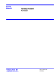
Module front View
F
A
G
B
E
C
D
A: Bridge+ (positive bridge voltage)
B: Input- (negative measurement signal)
C: Bridge- (negative bridge voltage)
D: Input+ (positive measurement signal)
E: Floating common
F: Sense+ (positive bridge voltage sensing)
G: Sense- (positive bridge voltage sensing)
The connector shell is connected to the case potential.
WARNING
• Do not apply input voltage exceeding the maximum input voltage or allowable
common mode input voltage.
• To prevent the possibility of electric shock, be sure to furnish protective earth
grounding of the SL1000.
• To prevent the possibility of electric shock, be sure to fasten the module screws.
Otherwise, the electrical and mechanical protection functions will not be
activated.
• Avoid continuous connection under an environment in which the allowable surge
voltage may occur.
16
IM 720120-51E
8
Strain Module (DSUB, Shunt-Cal) (701271)
Specifications
Item
Standard operating conditions
Effective measurementrange
Number of input channels
Maximum sample rate
Input format
Auto balance type
Auto balance range
Bridge voltage
Gauge resistance
Gauge factor
Frequency characteristics1
(–3 dB point when a sine wave
of amplitude 60 % of range is
input)
mV/V range support
Measurement range (FS) and
measurement range
DC accuracy1
Maximum input voltage
(at a frequency of 1 kHz or less)
Maximum allowable common
mode voltage
(at a frequency of 1 kHz or less)
Input connector
Common mode rejection ratio
A/D conversion resolution
Temperature coe
Bandwidth limit
Function
Standard accessories
Compatible accessories (sold
separately)
IM 720120-51E
Specifications
Temperature: 23° C±5° C
Humidity: 55%±10% RH
After a 30-minute warm-up and after calibration and auto balance
–FS to +FS (set using upper and lower limits)
2
100 kS/s
DC bridge (auto balancing), balanced differential input, and isolated
Electronic auto balance
±10000 µ STR (1 gauge method)
Select from 2 V, 5 V, and 10 V.
120 Ω to 1000 Ω (bridge voltage: 2 V)
350 Ω to 1000 Ω (bridge voltage: 2 V, 5 V, and 10 V)
1.90 to 2.20 (set in 0.01 steps)
DC to 20 kHz
Supports the strain gauge transducer unit system.
mV/V range = 0.5×(µSTR range/1000)
When using STR range
Measurement Range (FS) Measurement Range
500µSTR
−500µSTR to +500µSTR
1000µSTR
−1000µSTR to +1000µSTR
2000µSTR
−2000µSTR to +2000µSTR
5000µSTR
−5000µSTR to +5000µSTR
10000µSTR
−10000µSTR to +10000µSTR
20000µSTR
−20000µSTR to +20000µSTR
When using mV/V range
Measurement Range (FS)
Measurement Range
0.25mv/V
−0.25mV/V to +0.25mV/V
0.5mV/V
−0.5mV/V to +0.5mV/V
1mV/V
−1mV/V to +1mV/V
2.5mV/V
−2.5mV/V to +2.5mV/V
5mV/V
−5mV/V to +5mV/V
10mV/V
−10mV/V to +10mV/V
±(0.5% of FS+5µSTR)
Between Input+ and Input– 10 V (DC+ACpeak)
Between each terminal and earth ground
42 V (DC+ACpeak) (CAT I and CAT II, 30 Vrms)
9-pin D-Sub connector (female)
80 dB (50/60 Hz) or more (Typical2 )
16 bit (48000 LSB/range: Upper = +FS, Lower = –FS)
Zero point:
±5µSTR/° C(Typical2)
Gain:
±(0.02% of FS)/° C (Typical2)
Select from OFF, 1 kHz, 100 Hz, and 10 Hz
Cutoff characteristics: –12 dB/OCT (Typical2)
mV/V support. Supports the strain gauge transducer unit system.
Shunt calibration support. Built-in shunt calibration relay (1 gauge method).
Connector shell set for soldering
A1520JD (9-pin D-Sub): 2 pieces, A1618JD (connector shell): 2 pieces
Recommended bridge head 701957 (D-Sub 120 Ω, shunt-Cal, comes with a 5-m cable)
(sold separately)
Recommended bridge head 701958 (D-Sub 350 Ω, shunt-Cal, comes with a 5-m cable)
17
8 Strain Module (DSUB, Shunt-Cal) (701271) Specifications
Item
Specifications
• Highly sensitive measurements are made in the µ V level in strain measurements.
Therefore, take measures against noise at the strain sensor perimeter, bridge head,
and cable wiring.
• Depending on the noise environment, an error may result in the balance. Check the
influence before making measurements.
• The bridge head specified by YOKOGAWA has high noise resistance.
• When executing shunt calibration, be sure to calculate the shunt resistance in advance,
and execute it in a range so that the measured values do not exceed the range even
when the shunt resistance is ON.
• Some of the strain gauge sensors and bridge heads made by other manufacturers
do not have sensing wires connected. (No such problems with bridge heads made
by YOKOGAWA.) If such products are used, an error may result in the bridge voltage
leading to measurement errors, because sensing does not work effectively. Perform
sensing as close to the bridge head as possible. (There is no conversion cable for
sensing on D-Sub connector types.)
• The connector shell is connected to the case potential.
• When a bridge head (701957 or 701958) is used, the connector shell, cable shield, and
the bridge head case are all connected to the case potential of the DL750/DL750P.
• When a bridge head (701957 or 701958) is used, the floating GND is connected to the
bridge head case inside the bridge head.
• Be sure to execute balancing again when you change the range or the bridge voltage.
Precautions
1. Value measured under standard operating conditions.
2. The typical value is a representative or standard value. It is not strictly warranted.
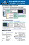
Module front View
5
3
4
9
8
1
2
7
6
1: Floating common
2: Sense- (positive bridge voltage sensing)
3: Shuntcal- (negative shunt signal)
4: Shuntcal+ (positive shunt signal)
5: Sense+ (positive bridge voltage sensing)
6: Bridge- (negative bridge voltage)
7: Input- (negative measurement signal)
8: Input+ (positive measurement signal)
9: Bridge+ (positive bridge voltage)
WARNING
• Do not apply input voltage exceeding the maximum input voltage or allowable
common mode input voltage.
• To prevent the possibility of electric shock, be sure to furnish protective earth
grounding of the SL1000.
• To prevent the possibility of electric shock, be sure to fasten the module screws.
Otherwise, the electrical and mechanical protection functions will not be
activated.
• Avoid continuous connection under an environment in which the allowable surge
voltage may occur.
18
IM 720120-51E
9
Acceleration/Voltage Module (with AAF)
(701275) Specifications
Item
Standard operating conditions
Effective measurement range
Number of input channels
Input coupling
Maximum sample rate
Input format
Frequency characteristics1
(–3 dB point when a sine wave
of amplitude 60 % of range is
input)
Voltage-axis range setting
Maximum input voltage
(at a frequency of 1 kHz or less)
Specifications
Temperature: 23° C±5° C
Humidity: 55%±10% RH
After a 30-minute warm-up and after calibration
Twice of setting range
2
AC, DC, GND, ACCL (acceleration), and GND
100 kS/s
Isolated unbalanced
Waveform observation mode:
DC to 40 kHz
Acceleration measurement mode: 0.4 Hz to 40 kHz
50mV to 100V renge (1-2-5 steps)
Acceleration (±5 V = ×1 range): ×0.1 to ×1 to ×100 (in 1-2-5 steps)
42V(DC+Acpeak)*2
Maximum allowable common
mode voltage
(at a frequency of 1 kHz or less)
Working voltage of safety standard
30Vrms(CAT and CAT II)3
Vertical (voltage) axis accuracy
DC accuracy1
Input connector
Input impedance
–3 dB point when AC coupled
low frequency attenuation point
Common mode rejection ratio
Residual noise level
(Input section shorted)
A/D conversion resolution
Temperature coefficient
Waveform measurement mode DC accuracy:
±(0.25% of range)
Acceleration measurement mode:
±(0.5% of range) at 1kHz
Metal BNC connector
1MΩ±1%, approx. 35pF
0.4 Hz or less (0.04 Hz or less when using the 701940)(Typical4)
Response time (only when
observing RMS)
Bandwidth limit
Probe attenuation setting
Sensor supply current (voltage)
Applicable acceleration sensor
IM 720120-51E
80dB(50/60Hz) or more(Typical4)
±100µV or ±0.1% of range, whichever is greater (Typical4)
16 bits(24000LSB/range)
When in waveform measurement mode (excluding AUTO filter)
Zero point:
±(0.02% of range)/° C(Typical4)
Gain:
±(0.02% of range)/° C(Typical4)
Select from OFF, Auto, 4 KHz, 400 Hz, and 40 Hz
Cutoff characteristics:
–12 dB/OCT (typical44, excluding AUTO)
Cutoff frequency (fc) when set to AUTO
Sample rate of 100 kHz or higher: fc = 40 kHz
Sample rate of 100 Hz to 50 kHz: fc = 40% of the sampling rate
Sample rate of 50 Hz or less: fc = 20 Hz
Cutoff characteristics when set to AUTO: –65dB at 2×fc (typical4)
Voltage probe
1:1, 10:1, 100:1, or 1000:1
Current probe
10 A:1 V (for the 700937/701933), 100 A:1 V (for the 701930/701931)
Connection cable (for low voltage 1:1)
366926 (non-isolated type BNC-alligator clip × 2: For measuring low voltage less than
or equal to 42 Vpeak)
Voltage probe (10:1 passive probe)
701940 17 to 46 pF: For measuring 600 V (DC+ACpeak) or less
Current probe (power can be supplied from the DL750/DL750P)
700937 (15 A), 701930 (150 A), 701931 (500 A), 701933 (30 A)
OFF/4mA±10%(approx. 22VDC)
Built-in amplifier type
Kistler Instrument Corporation: Piezotron, PCB Piezotronics Incorporated: ICP, ENDEVCO
Corporation: ISOTRON, etc.
19
9 Acceleration/Voltage Module (with AAF) (701275) Specifications
Item
Table of Cutoff Frequency
Characteristics of the AntiAliasing Filter (AAF)
Specifications
When the filter is set to Auto, the anti-aliasing filter and low-pass filter are automatically set
according to the sample rate.
Sample Rate
100kS/s4
50kS/s
20kS/s
10kS/s
5kS/s
2kS/s
1kS/s
500S/s
200S/s
100S/s
50S/s
20S/s to 5S/s
2S/s or less
Ext sample
AAF
0kHz
20kHz
8kHz
4kHz
2kHz
800Hz
400Hz
200Hz
80Hz
40Hz
20Hz
20Hz
20Hz
40kHz
Low-pass filter
OFF
OFF
OFF
4kHz
4kHz
4kHz
400Hz
400Hz
400Hz
40Hz
40Hz
40Hz
40Hz
OFF
1. Value measured under standard operating conditions.
Combined with the 10:1 passive probe
(701940)
Direct input (cable not complying with
the safety standard)
H
2.
H
BNC
L
3.
2.
L
3.
4. The typical value is a representative or standard value. It is not strictly warranted.
WARNING
• Do not apply input voltage exceeding the maximum input voltage or allowable
common mode input voltage.
• To prevent the possibility of electric shock, be sure to furnish protective earth
grounding of the SL1000.
• To prevent the possibility of electric shock, be sure to fasten the module screws.
Otherwise, the electrical and mechanical protection functions will not be
activated.
• Avoid continuous connection under an environment in which the allowable surge
voltage may occur.
20
IM 720120-51E
10
Frequency Module (701280) Specifications
Item
Standard operating conditions
Measurement function
Effective measurement range
Number of input channels
Data update rate
Output delay time
Input format
Input connector
Maximum input voltage
Maximum allowable common
mode voltage
Insulation resistance
Minimum measurement
resolution
Measured data resolution
Measurement accuracy1
Specifications
Temperature: 23° C±5° C
Humidity: 55%±10% RH
After a 30-minute warm-up and after calibration
Frequency, RPMs, RPSs, period, duty cycle, power supply frequency, pulse width, pulse
integration, and velocity
Twice of setting range
2
25kHz(40µs)
Up to 2 computation periods
Isolated unbalanced
Metal BNC connector
Module only (when 1:1 cable is connected, across input terminals H and L):
42V(DC+ACpeak)4
Combined with the 700929(10:1) (across the probe tips, H and L3):
420V(DC+ACpeak)2
Working voltage of safety standard
Module only (when 1:1 cable is connected, across input terminal L and earth)
30 Vrms (CAT I and CAT II)5
Combined with the 700929 (10:1) (across probe tip H or L and earth)
300 Vrms (CAT I and CAT II)3
500 VDC, 10 MΩ or more (across each input terminal and earth))
50ns
16 bits (24000LSB/range)
• When in frequency, RPM, RPS, or velocity measurement mode6
Measurement accuracy is specified according to the measurement range and input frequency
[Definition of measurement accuracy]
v±(0.05% of 10 div + accuracy dependent on the input frequency)
[Accuracy dependent on the input frequency]
When input frequency is 2 kHz or less: 0.05% of the input frequency + 0.001 Hz
Input frequency of 2 kHz to 10 kHz:
0.1% of the input frequency
Input frequency of 10 kHz to 20 kHz:
0.3% of the input frequency
Input frequency of 20 kHz or higher:
0.5% of the input frequency
• When in power supply frequency mode7
±0.03 Hz (0.01 Hz resolution)
When the center frequency is 50/60 Hz:
When the center frequency is 400 Hz:
±0.3 Hz (0.01 Hz resolution)
(Input set to AC100V or AC200V with sine wave input)
• When in period measurement mode6
Measurement accuracy is specified according to the measurement range and input period
[Definition of measurement accuracy]
±(0.05% of 10 div + accuracy dependent on the input period)
[Accuracy dependent on the input period]
0.05% of the input period
Input period of 500 µ s or greater:
0.1% of the input period
Input period of 100 µ s to 500 µ s:
0.3% of the input period
Input period of 50 µs to 100 µ s:
Input period of 50 µs or less:
0.5% of the input period + 0.1 µs
• When in duty cycle measurement mode86
Dependent on the input frequency
Input frequency of 1 kHz or less:
Input frequency of 1 kHz to 10 kHz:
Input frequency of 10 kHz to 50 kHz:
Input frequency of 50 kHz to 100 kHz:
Input frequency of 100 kHz to 200 kHz:
±0.1%
±0.2%
±1.0%
±2.0%
±4.0%
• When in pulse width measurement mode8
Measurement accuracy is specified according to the measurement range and input pulse width
IM 720120-51E
[Definition of measurement accuracy]
±(0.05% of 10 div + accuracy dependent on the input pulse width)
[Accuracy dependent on the input pulse width]
0.05% of the input pulse width
Input pulse width of 500 µ s or greater: 0.1% of the input pulse width
Input pulse width of 100 µ s to 500 µ s:
0.3% of the input pulse width
Input pulse width of 50 µ s to 100 µ s:
0.5% of the input pulse width + 0.1 µ s
Input pulse width of 50 µ s or less:
21
10 Frequency Module (701280) Specifications
Item
Input voltage range (±FS)
Input impedance
Specifications
When using 1:1 probe attenuation:
±1V, ±2V, ±5V, ±10V, ±20V, ±50V(±FS)
1MΩ±1 approx. 35pF
Pull-up function: 4.7 kΩ, approx. 5 V (pull-up can be turned ON only when the input is set
to Pull-Up 5V)
Input coupling settings
AC, DC
Probe attenuation setting
10:1, 1:1
Minimum voltage width for pulse 200mVP-P
detection
Bandwidth limit
Select from Full, 100 kHz, 10 kHz, 1 kHz, and 100 Hz
Cutoff characteristics: –12 dB/OCT (typical9)
Threshold
Set within the FS of the voltage range. Set in units of 1% of the FS.
Hysteresis
Select ±1%, ±2.5%, or ±5% of the FS of the voltage range
Preset function
Logic (5V/3V/12V/24V), electromagnetic pickup, zero crossing, pull-up, AC100V, AC200V,
and user-defined
Slope selection
Select rising or falling
Lower –3 dB point when AC
0.5 Hz or less (0.05 Hz or less when using the 700929) (typical9)
coupled
Chatter elimination function
OFF or 1 to 1000 ms (1 ms resolution)
Eliminates the chatter that occurs such when the contact input is turned ON/OFF.
Can discard the signal changes over the specified interval.
Input status indication function
Input status indication through the LEDs of each channel function
When in operation:
Illuminates in green when pulse input is detected
When overdriven:
Illuminates in red when the input voltage exceeds the range
Compatible probes/cables
Connection cable (1:1): Recommended 1
366926
Voltage probe (10:1 safety probe): Recommended 2
700929 (10:1 safety probe) .20 to 45 pF: For measuring 1000 V (DC+ACpeak) or less
1 Value measured under standard operating conditions.
Combined with the 700929
Direct input (cable not complying with the safety standard)
H
H
700929
BNC
2.
L
3.
4.
L
5.
3.
Withstand voltage: 1500 Vrms for 1 minute
Allowable transient surge voltage (between earth and input): 2100 Vpeak
6 Input waveform of 1 Vpp, rectangular wave, rise/fall time within 1 ms (input range: ±10 V, bandwidth limit: Full,
and hysteresis: ±1%)
7 Input waveform of 90 Vrms, sine wave (input range: AC100V, bandwidth limit 100 kHz, and hysteresis: ±1%)
8 Input waveform of 1 Vpp, rectangular wave, rise/fall time within 5 ns (input range: ±10 V, bandwidth limit: Full,
and hysteresis: ±1%)
9 Typical value represents a typical or average value. It is not strictly warranted.
WARNING
• Do not apply input voltage exceeding the maximum input voltage or allowable
common mode input voltage.
• To prevent the possibility of electric shock, be sure to furnish protective earth
grounding of the SL1000.
• To prevent the possibility of electric shock, be sure to fasten the module screws.
Otherwise, the electrical and mechanical protection functions will not be
activated.
• Avoid continuous connection under an environment in which the allowable surge
voltage may occur.
22
IM 720120-51E
10 Frequency Module (701280) Specifications
Specifications by Measurement Modes
Item
Frequency
Measurable frequency range
Selectable vertical axis range
Minimum resolution
RPMs
Measurable RPMs range
Selectable vertical axis range
Computing method
Selectable pulse/rotate range
RPSs
Measurable RPSs range
Selectable vertical axis range
Computing method
Selectable pulse/rotate range
Period
Measurable period range
Selectable vertical axis range
Minimum resolution
Duty cycle
Measurable duty cycle range
Selectable vertical axis range
Measurable frequency range
Measurement pulse selection
Minimum resolution
Power supply frequency
Measurable frequency range
Selectable vertical axis range
Center frequency setting
Minimum resolution
Pulse width
Measurable pulse width
Selectable vertical axis range
Measurement pulse selection
Minimum resolution
Pulse integration
Maximum pulse count
Selectable vertical axis range
Frequency measuring range
Computation function
Selectable Unit/Pulse range
Counter reset
Velocity
Selectable vertical axis range
Computing method
Selectable Distance/Pulse
range
IM 720120-51E
Specifications
0.01 Hz to 200 kHz
1Hz to 500kHz/range (1-2-5 steps)
0.001Hz
0.01 rpm to 100000 rpm (where the input frequency is DC to 200 kHz).
1 rpm to 100000 rpm range (1-2-5 steps)
Computed from the frequency based on the number of pulses per rotation
RPMs = Frequency/(pulse/rotate value) × 60
1 to 99999
0.001 rps to 2000 rps (where the input frequency is DC to 200 kHz).
0.1 rps to 2000 rps range (1-2-5 steps)
Computed from the frequency based on the number of pulses per rotation
RPSs = Frequency/(pulse/rotate value)
1 to 99999
5 ms to 50 s (where the minimum pulse width is 2 µs)
100 µs to 50 s range (1-2-5 steps)
0.1 µs
0 to 100%
10 to 200% range (1-2-5 steps)
0.1 Hz to 200 kHz
Select positive or negative pulse
0.01%
30 Hz to 70 Hz (when the center frequency is 50 Hz), 40 Hz to 80 Hz (when the center
frequency is 60 Hz), 380 Hz to 420 Hz (when the center frequency is 400 Hz)
1 Hz/div to 20 Hz range (0.01 Hz resolution)
Select 50 Hz, 60 Hz, or 400 Hz
0.01 Hz
2 µs to 50 s (where the input frequency is up to 200 kHz)
100 µs to 50s range (1-2-5 steps)
Select positive or negative pulse
0.1 µs
2×10⁹ pulses
500.0E+18 value/div to 10.00E–21 value/div (1-2-5 range: total of 123 ranges)
0.1 Hz to 200 kHz (where the minimum pulse width is 2 µs)
Set the physical amount per pulse and display by converting the values intophysical values
such as distance and flow rate.
–9.9999E+30 to +9.9999E+30
Manual reset and over-limit reset
500.0E+18 range to 10.00E–21 range (1-2-5 range: total of 123 ranges)
Set the amount of displacement per pulse and compute the velocity from the frequency
Automatic unit time conversion of s, min, and hour.
–9.9999E+30 to +9.9999E+30
23
10 Frequency Module (701280) Specifications
Functional Specifications
Item
Deceleration prediction
Stop prediction
Smoothing
Pulse average
Offset function
24
Specifications
Computes the deceleration condition in realtime when the pulse input is cut off.
Can be specified when measuring the frequency, RPMs, RPSs, period, and velocity
Sets the frequency to 0 after a certain time elapses after the pulse input is cut off.
Stop interval setting: Set in the range of 1.5 to 10 times (10 settings) the period of the
pulse measured last
Can be specified when measuring the frequency, RPMs, RPSs, period, and velocity
Computes the moving average of the measured data using the specified time
Specified time: 0.1 to 1000 ms (0.1 ms resolution)
Can be specified on all measurement parameters
Performs frequency measurement per specified number of pulses. When fluctuation exists
periodically in the pulse interval, the fluctuation can be eliminated.
Specified number of pulses: 1 to 4096
Can be specified when measuring the frequency, RPMs, RPSs, power supply frequency,
period, pulse integration, and velocity
Observe fluctuation with respect to the offset frequency
Offset range:
Can be set up to 100 times the maximum range value
• Frequency:
0 Hz to 200 kHz
• RPMs:
0 rpm to 50 krpm
• RPSs:
0 rps to 1000 rps
• Period:
0 s to 50 s
• Duty cycle:
0% to 100%
• Pulse width:
0 s to 50 s
• Pulse integration: –1.0000×10²² to 1.0000×10²²
• Velocity:
–1.0000×10²² to 1.0000×10²²
IM 720120-51E
11
High-Speed 100 MS/s, 12-Bit Isolation Module
(720210) Specifications
Item
Standard operating conditions
Effective measurement range
Number of input channels
Input coupling
Maximum sample rate
Input format
Frequency characteristics1
Voltage-axis range setting
Maximum input voltage
(at a frequency of 1 kHz or less)
Maximum allowable common
mode voltage
(at a frequency of 1 kHz or less)
Vertical (voltage) axis accuracy
DC accuracy1
Input connector
Input impedance
–3 dB point when AC coupled
low frequency attenuation point
Common mode rejection ratio
Residual noise level
(Input section shorted)
Withstand voltage
Insulation resistance
A/D conversion resolution
Temperature coefficient
Bandwidth limit
Probe attenuation setting
Specifications
Temperature: 23° C±5° C
Humidity: 55%±10% RH
After a 30-minute warm-up and after calibration
Twice of setting range
2
AC, DC, and GND
100 MS/s
Isolated unbalanced
(–3 dB point when sine wave of amplitude 60 % of range is input) DC to 20 MHz
50 mV to 200 V range (1-2-5 steps)
Combined with the 700929(10:1)2
1000 V (DC+ACpeak) CATII
Direct input or cable not complying with the safety standard4 200 V (DC+ACpeak)
Working voltage of safety standard
Combined with the 700929 (10:1)3
1000 Vrms (CAT II)
Direct input or cable not complying with the safety standard5
42 V (DC+ACpeak) (CAT I and CAT II, 30 Vrms)
100mV to 200 V range:
±(0.5% of range)
BNC connector (isolated type)
1 MΩ ± 1%, approx. 35 pF
10 Hz or less (1 Hz or less when using the 700929)
80 dB (50/60 Hz) or more (typical6)
±1.1 mV or ±1.5% of range whichever is greater (Typical6)
1500 Vrms for 1 minute (across each terminal and earth) (60 Hz)
500 VDC, 10 MΩ or more (across each input terminal and earth)
12 bit (1500 LSB/range)
Zero point: 100 mV to 200 V range: ±(0.1% of range)/° C(Typical6)
Gain: ±(0.05% of range)/° C(Typical6)
Select from OFF, 2 MHz, 1.28 MHz, 640 kHz, 320 kHz, 160 kHz, 80 kHz, , 40 kHZ, 20 kHz,
and 10 kHz
Cut-off characteristics: –12 dB/OCT (when 2 MHz, Typical6)
Voltage probe: 1:1, 10:1, 100:1, 1000:1
Current probe: 10 A:1 V (for the 700937/701933), 100 A: 1 V (for the 701930/701931)
1 Value measured under standard operating conditions.
Combined with the 700929
Direct input (cable not complying with the safety standard)
H
H
700929
BNC
2.
L
3.
4.
L
5.
Withstand voltage: 1500 Vrms for 1 minute
Allowable transient surge voltage (between earth and input): 2100 Vpeak
6 Typical value represents a typical or average value. It is not strictly warranted.
IM 720120-51E
25
11 1 High-Speed 100 MS/s, 12-Bit Isolation Module (720210) Specifications
WARNING
• Do not apply input voltage exceeding the maximum input voltage or allowable
common mode input voltage.
• To prevent the possibility of electric shock, be sure to furnish protective earth
grounding of the SL1000.
• To prevent the possibility of electric shock, be sure to fasten the module screws.
Otherwise, the electrical and mechanical protection functions will not be
activated.
• Avoid continuous connection under an environment in which the allowable surge
voltage or higher voltage may occur.
26
IM 720120-51E
12
Basic Defining Equation of Strain
Definition of Strain
(1)
DL/L = e
e Strain
L: Initial length of the material
∆L: Amount of change due to external strain
Definition of the Gauge Factor
Gauge factor (K) refers to the ratio between the mechanical strain and the change in the
resistance of the strain gauge resistor.
E=
$L
$R/R
=
L
K
(2)
($R/R)=K×E
(3)
R G auge resistance
DR Amount of change in resistance when a strain is received
Normally, K=2.0. However, the value varies depending on the strain gauge material.
General Equation of the Measured Voltage (V) and Strain (ε) of the
Wheatstone Bridge (1 Gauge Method)
If we assume V to be the voltage measured on the bridge and E to be the voltage
applied to the bridge,
V = (1/4)×E×(DR/R)
(4)
From equation (3)
(DR/R) = K×e
Thus, V = (1/4)×E×K×e
(5)
• When Determining the Strain (ε) from the Measured Voltage (V) (Strain Gauge
(1Gauge Method))
If we derive ε from equation (5)
e = (4/K)×(V/E)
(6)
• When Determining the Measured Value of the Strain Gauge Sensor (e) from the
Voltage Measured on the Bridge (V) (Strain Gauge Sensor)
Assuming e to be the measured value (measured value of the strain gauge sensor:
mV/V unit) and substituting ε = e in equation (6),
e = (4/K)×(V/E)
(7)
In the case of a strain gauge sensor, set the Gauge Factor (K) to 2 on the SL1000
unit. If you change the value of K, conversion is made using the above equation.
IM 720120-51E
27
13
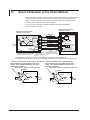
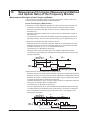
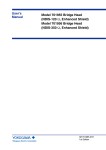
Shunt Calibration of the Strain Module
Shunt calibration is used to correct the gain of strain measurements by inserting a known
resistance (shunt calibration resistance (shunt resistance)) in parallel with the strain
gauge. The Strain Module (701271(STRAIN_DSUB) supports shunt calibration and
contains a built-in relay circuit for shunt calibration.
To execute shunt calibration, a bridge head that supports shunt calibration
(701957/701958) is needed.
Measurement instrument
(example: SL1000)
Bridge Head 701957/701958
(with shunt cal support)
Shunt resistor
Sense+
Bridge+ Bridge+
Bridge-
R
Shuntcal-
Input+
InputSense+
R
Shuntcal+
R
Input+
Input-
BridgeSense-
GND
terminal
SenseShuntcal+
Shuntcal-
Floating
Common
Case
Sense+
Sense-
B8023WP
The floating common of the module is
grounded within the bridge head. 1
9
6
8
7
5
2
4
3
1
Twist
Bridge+
BridgeInput+
Twist
Input-
9
6
8
7
5
2
4
3
1
Sense+
Twist
SenseSuntcal+
Twist
Shell
The connector shell is
connected to the case
potential of the bridge
head. 2
+
-
SuntcalFloating Common
The shield is connected to
the bridge head case and
the measurement instrument
case. 2
701271
STRAIN_DSUB
Bridge
Power
+
-
AD
Sense+
SenseShuntcal+
Shuntcal
ON/OFF
ShuntcalAll module
Floating signals are
Common
isolated.
Shell
Shield
Module
The connector shell is connected to the case
potential of the measurement instrument. 2
Case
1. The GND (floating common) of the module is connected to the case potential inside the bridge box.
2. The bridge head case, the cable shield, and the measurement instrument case are connected as measures against noise.
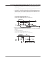
• When correcting the gain on the negative side (normal)
Shunt calibration relay circuit (Built into the strain
module. Turns ON/OFF automatically when shunt
calibration is executed.)
Shunt resistor (Applied to the bridge head)
• When correcting the gain on the positive side
Shunt calibration relay circuit (Built into the strain
module. Turns ON/OFF automatically when shunt
calibration is executed.)
Shunt resistor, when correcting the positive side
Bridge+
Bridge+
120 7
120 7
In+
In120 7
120 7
In+
In120 7
Bridge-
28
Bridge
voltage
120 7
Bridge
voltage
Bridge-
IM 720120-51E
13 Shunt Calibration of the Strain Module
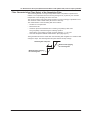
Shunt Calibration Procedure
1. Calculate the strain value (µSTR) corresponding to the shunt resistor to be used.
For the calculation procedure, see “Calculating the Shunt Resistance” in the next
section.
2. Execute balancing without applying a load to the strain gauge and correct the
zero point.
3. Execute shunt calibration and correct the gain.
Usually, the negative gain is corrected. However, if you are correcting the positive
gain, change the position of the shunt resistor as shown in the right figure in the
previous page.
• Shunt calibration
• Balance
Strain
Before
execution
Strain
After
execution
Current measured
value 1
Strain input
P2:X
The zero point is
corrected when
balancing is executed.
After execution
Gain is corrected.
Before execution
Strain input
P2:Y
The strain value corresponding to the
shunt resistor is set to P2:Y of the setup menu.
1. Automatically obtained when shunt calibration is executed.
Execute shunt calibration according to the procedures appropriate for the instrument that
you are using (SL1000 unit for example).
Note
• When executing shunt calibration, select an appropriate range so that the measured values
do not exceed the range when the shunt calibration relay circuit is ON. The SL1000 unit
attempts shunt calibration within the current specified range.
• If shunt calibration fails (the measured value exceeds the range, for example), an error
message is displayed. In such case, change the range and execute shunt calibration again.
Taking Measures against Noise
Because measurements are made at the µV level, the strain gauge is extremely
susceptible to noise. If the execution of balancing or shunt calibration fails, it may be due
to the effect of noise. Check the following points.
• Because the strain gauge is attached away from the bridge head, it is recommended
that twisted wire be used for extension.
• Use a bridge head with high noise resistance. It is recommended that YOKOGAWA
bridge head (701957/701958) with high noise resistance be used.
IM 720120-51E
29
13 Shunt Calibration of the Strain Module
Calculation of the Shunt Resistance
To execute shunt calibration, the shunt resistance (Rs) and the expected strain (ε) need
to be calculated in advance. Use ε as given in the equation below (normally a negative
value). Enter the value into “P2Y” under the shunt calibration execution menu. However,
when using the general method given for shunt calibration (the easy method), an error
of 1 to 2% can be introduced as the strain value (ε) increases. Therefore, calculate using
the detailed method whenever possible. Also, you must select a setting range value that
will not result in an overrange.
Equation for Rs and e When Executing Shunt Calibration
General Equation
DR/R = K×e DR = R - R//Rs
(1): Basic Equation of Strain
(2): Equation of the change in resistance when the shunt
resistance is ON
In this manual, the parallel equation of resistors are expressed as follows:
R//Rs=
1
1
R
+
1
Rs
= R×Rs
R+Rs
If $R is cancelled out from (1) and (2),
Rs=R×(1-K×E)/(K×E)
E:
K:
R:
$R:
Rs:
(Equation A): General equation used to calculate the
shunt resistance (includes error)
Strain (strain you wish to generate when the shunt resistance is turned ON)
Gauge factor
Bridge resistance
Resistance change
Shunt resistance (shunt resistance you wish to derive)
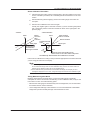
General Equation
V0=E×(R1×R3–R2×R4)/{(R1+R2)×(R3+R4)} (1): Basic Equation of Wheatstone Bridge
When shunt calibration is ON,
V0=E×(R1×R3–R'×R4)/{(R1+R')×(R3+R4)}
R'=R2//Rs
R1=R2=R3=R4=R
(2): Equation when turned ON
(3): Equation of combined resistance R'
(4): Since R1 to R4 are equal, we represent
them as R
Also, from the basic equation of strain,
V0/E=K×E/4
(5): Basic equation of strain
If V0/E and R1 to R4 are cancelled out from (2), (3), (4), and (5),
Rs=R×(1–K×E/2)/(K×E)
E:
V0:
R1 to R4:
Rs:
R':
(Equation B): Detailed equation used to calculate
the shunt resistance (no error)
Bridge voltage
Bridge output voltage
Bridge resistance (except, R1=R2=R3=R4)
Shunt resistance (shunt resistance you wish to derive)
Combined resistance when the relay is turned ON (R'=R//Rs)
R1
R4
V0
R2
E (Bridge power supply)
R3
Rs
30
IM 720120-51E
13 Shunt Calibration of the Strain Module
Calculation Example
When Determining the Corresponding Shunt Resistance (Rs) from the Strain (ε)
Given a gauge factor (K) of 2,
Detailed equation Rs = R×(1–e)/(2×e)
(6)
(equation B)
General equation Rs = R×(1–2×e)/(2×e)
(7): Error of 1 to 2% present
(equation A)
Desired Strain
e(mSTR)
1,000
2,000
5,000
10,000
Derived by the Detailed
Equation (6) Rs Value (W)
R = 120W
R = 350W
59,940
174,825
29,940
87,325
11,940
34,825
5,940
17,325
Rs value (W) Derived by the
General Equation (7)
R = 120W
R = 350W
59,880
174,650
29,880
87,150
11,880
34,650
5,880
17,150
When Determining the Corresponding Strain (ε) from the Shunt Resistance (Rs)
If we derive e from equation (6) and (7),
Detailed equation
(8)
e = 1/(1+2×Rs/R)
(equation B)
General equation
(9): Error of 1 to 2% present
e = 1/{2×(1×Rs/R)}
(equation A)
When the Bridge Resistance R is120 W
RS Value(W)
60,000
30,000
12,000
6,000
Strain e(mSTR) Derived
by the Detailed Equation
(8)
999
1,996
4,975
9,901
Strain e(mSTR) Derived
by the General Equation
(9)
998
1,992
4,950
9,804
When the Bridge Resistance R is350 W
IM 720120-51E
RS Value(W)
Strain e(mSTR) Derived
Strain e(mSTR) Derived
by the Detailed Equation by the General Equation
(8)
(9)
180,000
90,000
36,000
18,000
971
1,941
4,838
9,629
970
1,937
4,814
9,537
31
14
Measurement Principles (Measurement Method
and Update Rate) of the Frequency Module
Measurement Principles of the Frequency Module
The measurement principles of period, frequency, pulse width, and duty cycle on the
frequency module (701280 (FREQ)) are described below.
Period and Frequency Measurement
The frequency module updates the waveform at a rate of 25 kHz (40-ms interval). The
measurement method differs for frequencies above 25 kHz and below 25 kHz.
• When the input signal is less than or equal to 25 kHz, measurement is made as
described in (1).
• When the input signal is greater than or equal to 25 kHz, measurement is made as
described in (2).
• The sequence of processing described below is performed simultaneously through
pipeline processing. Thus, the period (t) and frequency (f) are updated every 40 ms.
(1)When the input signal is less than or equal to 25 kHz
Measures the time of occurrence of the pulse edge (T1) in measurement interval A.
Measures the time of occurrence of the pulse edge (T2) in measurement interval B.
Calculates the period (t) = T2 – T1 in measurement interval C.
The frequency (f) is calculated as 1/period (t).
When the period of the input pulse spans over multiple measurement intervals,
computation is performed at the measurement interval following the interval in which
the edge is detected.
A
Measurement
interval: 40 Ms
B
40 Ms
C
40 Ms
Period (t)
Time: T2
Time: T1
Input
pulse
Period (t) = T2–T1
Frequency (f) = 1/period (t)
(2)When the input signal is greater than or equal to 25 kHz
Measures the time of occurrence of the last pulse edge (Te1) in measurement interval A.
Measures the time of occurrence of the last pulse edge (Te2) in measurement interval B.
Measures the number of pulses between the last pulse edge in measurement interval
A and the last pulse edge of measurement interval B.
Calculates the period (t) = (Te2 – Te1)/the number of pulses in measurement interval C.
Period (t) is the average value of multiple pulses.
The frequency (f) is calculated as 1/period (t).
If the input pulse period is short, the DL750/DL750P automatically takes the average
of multiple pulses and calculates the period and frequency. Therefore, the resolution
does not degrade even when the input pulse period is short, and highly accurate
measurement is possible.
A
Measurement
interval: 40 Ms
B
C
40 Ms
40 Ms
Number of pulses: 3
Time: Te1
Input
pulse
32
Time: Te2
Period (t) = (Te2 – Te1)/3
Frequency (f) = 1/period (t)
IM 720120-51E
14 Measurement Principles (Measurement Method and Update Rate) of the Frequency Module
Pulse Width and Duty Cycle Measurement
• When the input signal is less than or equal to 25 kHz, measurement is made as
described in (1).
• When the input signal is greater than or equal to 25 kHz, measurement is made from
the last waveform in the measurement interval as described in (2).
• The sequence of processing described below is performed simultaneously through
pipeline processing. Thus, the period (t) and frequency (f) are updated every 40 ms.
(1)When the input signal is less than or equal to 25 kHz
Measures the times of occurrences of pulse edges (T1, T2, and T3) in measurement
intervals A and B.
In measurement interval C:
For pulse width: Calculates pulse width = T2 – T1.
For duty cycle: Calculates duty cycle = (T2 – T1)/(T3 – T1).
B
40 Ms
A
Measurement
interval: 40 Ms
C
40 Ms
Pulse width
Time: T1
Time: T2 Time: T3
Input
pulse
Pulse width = T2 – T1
Duty cycle = (T2 – T1)/(T3 – T1)
(2)When the input signal is greater than or equal to 25 kHz
Measures the times of occurrences of pulse edges (T1, T2, and T3) in measurement
interval A.
In measurement interval B:
For pulse width: Calculates pulse width = T2 – T1.
For duty cycle: Calculates duty cycle = (T2 – T1)/(T3 – T1).
A
Measurement
interval: 40 Ms
B
40 Ms
Pulse width
T1 T2 T3
Input
pulse
Pulse width = T2 – T1
Duty cycle = (T2 – T1)/(T3 – T1)
IM 720120-51E
33
14 Measurement Principles (Measurement Method and Update Rate) of the Frequency Module
Computation Format (Resolution) of the Frequency Module
The computation flow on the frequency module is indicated below.
Range value
Offset value
Internally, all calculations
are performed using
floating-point.
Input
32-bit counter
A(Float)
24000 LSB/
range
24000 LSB
/range
1 LSB weight
C(Float)
D(Float)
E(Binary)
Various
computations
Frequency
Period
....
50 ns resolution
Binary
Floatingpoint
computation
Floating
point data
Float
Computation (floating-point)
Float
ACQ
Memory
16bit Binary
The frequency module measures the period of the input signal using a 32-bit counter of
50-ns resolution. Therefore, the minimum resolution of the counter values is 50 ns.
Various computations are performed in floating point format. The data that is output from
the frequency module and written to the acquisition memory (ACQ Memory) is 16-bit
binary data. The data is converted using a weight of 1 LSB that is determined by Value/
div. The data is normalized to 2400 LSB/div when displayed on the screen.
Input: Conversion from the 32-bit Counter Value to Floating Point
Converts the count value obtained using the 32-bit counter with 50-ns resolution to
floating point format, and determines period A using the following equation.
Period: A (float) = (count value) × 50 ns
Computation
Various computations are performed in floating point format based on the settings.
Example) Frequency: C (float) = 1/A (float)
Calculation of the 1 LSB Weight of the Output
The 1 LSB weight of the output is determined from the range.
Since range = 24000 LSB,
1 LSB weight of the output =range/24000
Computation Output: Conversion from Floating Point to 16-bit Binary
(When Offset Is 0)
When the offset value is 0, offset calculation is not performed, and C (float) = D (float).
The data is converted into 16-bit binary data and written to the acquisition memory (ACQ
Memory).
16-bit binary data: E (binary) = D (float)/(1 LSB weight of the output)
Offset Computation
When the offset value is not 0, the offset value is computed in floating point format using
the following equation and converted to 16-bit binary data.
D (float) = C (float) – offset value (float)
In offset computation, if the computed result C is equal to the offset value, the output is 0.
If the computed result C (float) is less than the offset value, E (binary) is negative.
34
IM 720120-51E
14 Measurement Principles (Measurement Method and Update Rate) of the Frequency Module
Filter Characteristics (Time Delay) of the Smoothing Filter
The smoothing filter is a moving average filter in which computation is performed in
realtime. The computation interval of moving average is 40 ms (25 kHz). It is constant
independent of the sampling rate of the main unit.
The moving average order (the number of points of moving average) is specified in time.
The maximum value is 25000 order (when set to 1000 ms).
The characteristics of the smoothing filter are as follows:
• The filter is a low-pass filter.
• Pass band is flat.
• Has linear phase characteristics and constant group delay by filter order.
The group delay is derived using the following equation.
Group delay = (the number of points of moving average – 1) × 40 ms/2
• Has comb-shaped bandwidth characteristics. (See page app-43.)
The figure below shows the result when the smoothing filter is applied to a waveform that
changes in steps. The switching filter setup time follows the step change.
Smoothing filter setup time
Waveform after applying
the smoothing filter
Waveform before applying
the smoothing filter
IM 720120-51E
35