1
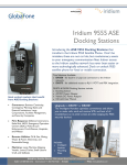
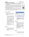
DRS-I Dynamic Relay Station type I Key Features: 1. 2. 3. 4. 5. 6. 7. 8. 9. Multifunctional radio relay station Support SATCOM to Radio interface Selective relay Relay / dispatch modes Simple user interface User friendly Ruggedize Suitable for field use Power from radio Specifications Kit content 1. 2. 3. 4. 5. 6. Size : 130mm X 43mm X 91mm Weight : 430gr Temp : -20C0 to+55C0 Immersion : 1meter Test method : MIL-STD-810 , MIL-STD-461 Power consumption : 100mW – 350mW 1. 2. 3. 4. DRS-I DRS-2-Radio Cable DRS-2-Iridium Cable User manual Satellite communication DRS-I (CU-2961) Satellite communication Operator’s Manual 8 9 14 HS-1 Panel System Architecture Setup Operating Special Keys Troubleshoot 2 6 P P O 13 7 DISP 12 5 3 O 4 Panel Description: Content: 1. 2. 3. 4. 5. 6. Radio-2 Radio-1 2 1 10 11 HS-2 1 1. 2. 3. 4. 5. 6. 7. radio audio connectors HS audio connectors channels selector HS volume radio selector Light ON/OFF DISP Change 8. 9. 10. 11. 12. 13. 14. Radio-1 LED Radio-2 LED LCD Enable / P Cancel / O Navigating keys Enter key Radio SATCOM Radio System Architecture 1. 2. 3. By Opening the bridge at both sides – the 2 networks become connected. Both networks becomes one network. Selective mode: read page 3. 1st VHF/UHF Network Bridge 2nd VHF/UHF Network Bridge 2 VHF UHF System Architecture 1. 2. Satellite communication By Opening the bridge at both sides – the 2 networks become connected. Both networks becomes one network. 3. Selective relay mode: pushing O button for 3 seconds at one side of the DRS will disable traffic from this side to be forwarded to the other side. 4. Press P button for 3 seconds, at that side again, will enable this side’s traffic, and the DRS will be symmetric again. 1st VHF/UHF Network 2nd VHF/UHF Network Bridge 3 Setup DRS-I with 2-way Radio (Power from audio connector) 1. 2. 3. 4. 5. Connect Antenna to the VHF radio Connect “Radio” audio connector of cable-2961 to the VHF Radio audio con Connect “DRS” audio connector of cable-2961 to Radio-1 port of DRS-I Connect HS to HS-1 port at the DRS-I Connect Iridium-cable to the earphone jack of the Iridium 9555 phone. Turn on the Iridium power, and set the Iridium volume to max. 6. Connect Iridium-cable to Radio-2 Port of DRS-I 7. Make sure the DRS-I LCD is working 8. Push + together to toggle lights on/off 2 4 HS-1 VHF radio Radio-1 Cable -2961 7 Radio-2 8 3 P O P O Iridium-cable HS-2 1 6 5 Battery 4 Setup DRS-I with VHF Radio (No power from audio connector) 1. 2. 3. 4. 5. 6. 7. Connect Antenna to the VHF radio Connect power-adaptor to the bottom of the VHF Radio Connect “short” audio connector of cable-2961 to the VHF Radio audio con Connect power plugs together Connect “long” audio connector of cable-2961 to Radio-1 port of DRS-I Connect HS to HS-1 port at the DRS-I Connect Iridium-cable to the earphone jack of the Iridium 9555 phone Turn on the Iridium power, and set the Iridium volume to max. 8. Connect Iridium-cable to Radio-2 Port of DRS-I 9. Connect battery below the power-adaptor 10. Make sure the DRS-I LCD is working 3 8 2 HS-1 4 Radio-1 Cable -2961 2-way radio 10 Radio-2 5 P O P O Iridium-cable HS-2 1 8 7 6 PW-296X 9 Battery 5 DRS-I – Relay Operation 1. Setup 1. Connect Radio to Radio-1 port (see p. 2) 2. Connect 2nd device at Radio-2 side: 1. Another VHF/UHF/HF with 2961-100 cable 2. No need for power supply at both sides. One side is enough. 3. To connect Iridium-9555, set MENU->RADIO2 -> IRDM 3. Set MENU->GATEWAY->OPEN+ ENTER (default after powerup) 4. Connect 2 HS, one to HS-1, one to HS-2. set high volume for both HS. 5. Light ON (“Up”+”Right”) 6. Call units from one of the HS – make sure both LEDs are RED 7. When unit from F1 calls, LED1=GREEN and LED2=RED 8. When unit from F2 calls, LED2=GREEN and LED1=RED Satellite communication 2. Noises from one channel 1. Connect HS/SPKR and listen to the incoming channel 2. Push long-X on the side of that channel 3. Push “V” to enable good MSG 4. MSGs from the “clean” channel will automatically override the noisy channel 5. Push long-V once noises disappeared 3. Noises from both channels 1. Repeat section 2 for both channels 2. If 2 LEDs are GREEN, and “V” pushed, a MSG will go out only if channel is not busy 6 Display Modes 1. The LCD has 2 display modes: 1. Use & together to switch between display mode. 2. MENU : setting DRS functions. while browsing MENU, 2nd line shows a brief RELAY info 3. RELAY : informative display for a relay station 2. LCD content changes from MENU display mode to RELAY display mode: GATE OPEN GATE RADIO 2 IRDM MENU RELAY CLOS RADIO 2 VHF RADIO 2 MENU UHF RADIO 2 HF RELAY Radio-2 Type GATEWAY Radio-1 Type Value Function [_ _ _ _ _ _ _] [_ _ _ _] [][] [ ] [][] [_ _ _ _] [_ _] [_ _ _ _] [_ _ _] [_ _] [_ _ _] OPRTR-2 GATEWAY OPRTR-1 OPRTR-2 Radio-2 GATEWAY Radio-1 OPRTR-1 7 DRS-I MMI 1. 2. 3. 4. 5. 6. 7. The table below describe the menu order Use “DOWN” / “UP” to change line Use “Right” / “Left” to change value Press ENTER to set new value to selected function Setting GATEWAY= OPEN, connects 2 sides of the DRS Setting GATEWAY = CLOS, disconnect 2 sides of the DRS Setting RADIO2 : User can adjust Radio2 type as follow 1. Iridium 9555 (Default) 2. VHF 2-way Radio 3. UHF 2-Way Radio 4. HF 2-Way Radio Open Relay Display RAD >> SAT AUTO << AUTO MENU Structure GATEWAY Close Relay Display RADIO2 RAD -MAN -- SAT MAN OPEN IRDM CLOS VHF Selective Relay Display UHF RAD >> SAT AUTO -- MAN HF 8 DRS-I Lights Satellite communication 1. Lights 1. Push “UP” & “Right” together to switch light to “TEMP” 2. Push “UP” & “Right” together again to switch light back to “OFF” 3. Any time the DRS is been connected to power, the lights goes “OFF” 4. TEMP: LCD’s backlight is “ON” for 6 seconds after any key press 5. LEDS: will represent traffic (GREEN=RX,RED=TX) unless LIGHT=OFF 9 DRS-I Troubleshooting 1. Can’t see what is written in the LCD 1. Make sure all sides of the cables are connected well 2. See p. 2, and check all the setup steps again 3. Push “UP”+”RIGHT” together 2. GREEN LED doesn’t light when someone transmit to me 1. Make sure frequency is the same and check antenna 2. Check that LEDs are lite (push PTT shortly, RED LED should be lite) 3. Check MENU->RADIO2 is set correctly Satellite communication 3. HS can’t hear calls 1. 2. 3. 4. Select 1 at the “Radio Select” knob Turn Volume clockwise until HS1 volume is maximal Repeat for HS2 (select 2 at “Radio Select”) Normal position should be “radio select” on “middle” 4. Improper connection between 2 networks via SATCOM 1. 2. Make sure MENU -> RADIO2 -> IRDM is set Push “Enter”, and switch back to RELAY display mode 10