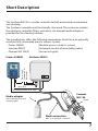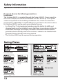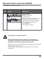
1
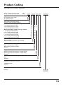
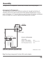
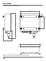
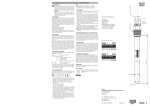
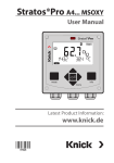
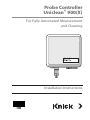
Probe Controller Uniclean® 900(X) For Fully Automated Measurement and Cleaning Installation Instructions Warranty Defects occurring within 3 years from delivery date shall be remedied free of charge at our plant (carriage and insurance paid by sender). Sensors, fittings, and accessories: 1 year. ©2010 Subject to change without notice Return of Products Under Warranty Please contact our Service Team before returning a defective device. Ship the cleaned device to the address you have been given. If the device has been in contact with process fluids, it must be decontaminated/disinfected before shipment. In that case, please attach a corresponding certificate, for the health and safety of our service personnel. Disposal Please observe the applicable local or national regulations concerning the disposal of “waste electrical and electronic equipment”. Trademarks The following trademarks are used in this user manual without further marking CalCheck®, Calimatic®, Protos®, Sensocheck®, Sensoface®, ServiceScope®, Uniclean®, VariPower®, Ceramat®, SensoGate®, ComFu® are registered trademarks of Knick Elektronische Messgeräte GmbH & Co. KG, Germany SMARTMEDIA® is a registered trademark of Toshiba Corp., Japan ZigBee™ is a trademark of Zigbee Alliance 3 4 Table of Contents Probe Controller for Fully Automated Measurement and Cleaning Warranty......................................................................................................................................... 2 Return of Products Under Warranty..................................................................................... 2 Disposal.......................................................................................................................................... 2 Trademarks.................................................................................................................................... 2 Short Description............................................................................................. 7 Intended Use...............................................................................................................................10 Safety Information....................................................................................................................11 Application in Hazardous Locations: Installation Precautions.................................12 Rating Plates...............................................................................................................................12 Product Coding..........................................................................................................................13 Product Line..............................................................................................................................14 Assembly......................................................................................................... 15 Arrangement of Components..............................................................................................15 Uniclean 900(X) - Wall Mounting.........................................................................................16 Uniclean 900(X) - Pipe Mounting........................................................................................17 Assembly......................................................................................................................................18 Media Adapter............................................................................................................................18 Media Supply: Uniclean 900(X)..................................................................... 19 Compressed Air, Water, Purge Air, Auxiliary Media.......................................................19 Arrangement of Functional Elements...............................................................................20 Media Supply with Media Adapter.....................................................................................21 Media Adapter and Metering Pump..................................................................................22 Metering Pump..........................................................................................................................23 Media Adapter and Metering Pump.........................................................................24 Bill of Material for Media Adapter .............................................................................24 Bill of Material for Metering Pump.............................................................................24 Media Connection....................................................................................................................25 Media Connection............................................................................................................26 Bill of Material for Media Connection, Cleaning and Rinse Function...........26 Attaching the Media Connection to the Uniclean 900(X).................................27 Pneumatic Couplings on the Uniclean 900(X)...............................................................28 Attaching the Media Connection to Ceramat WA 150(X) - Example...................... 29 5 Table of Contents Probe Controller for Fully Automated Measurement and Cleaning Electrical Installation..................................................................................... 30 Connecting Preassembled Cables......................................................................................31 Terminal Assignments of Uniclean 900(X).......................................................................32 Ex Connection to DCS.............................................................................................................36 Control Programs and Measurement Procedures.........................................................37 Uniclean 900(X) Specifications...................................................................... 39 Appendix......................................................................................................... 44 Pneumatic Diagram of Uniclean 900.................................................................................45 Pneumatic Diagram for Media Connection to Uniclean 900....................................46 Recommended Connection of Standard Retractable Housings, e.g. InTrac 7xx..47 Commissioning of Hardware ...............................................................................................52 Start-up: “Plug and Play” . ......................................................................................................53 Start-up Program..............................................................................................................54 Manual Control via Protos 3400(X)............................................................................55 Selected Cleaning Agents for Uniclean 900 and their Applications......................56 EC-Type-Examination Certificate.........................................................................................59 FM Certificate of Compliance...............................................................................................60 Index..............................................................................................................................................61 Notice These installation instructions do NOT describe - how to operate the sensor lock-gate - how to control the programs via Protos 3400(X). The user manuals for sensor lock-gates such as SensoGate WA 130(X), Ceramat WA 150(X), Ceramat WA160(X) and the user manuals for Protos 3400(X) as well as the PHU 3400(X)‑110 module are available for free download at www.knick.de. 6 Short Description The Uniclean 900 (X) is a probe controller for fully automated measurement and cleaning. The Uniclean is modular and functionally structured. The enclosure contains the electronic controller, filters, and valves. An external media adapter is provided for the cleaning solution. The manufacturer offers the following components which form an optimally matched, fully automated process analysis system: • Protos 3400(X) (Modular process analysis system) • Uniclean 900(X) (Automatic control of retractable probes) • Ceramat WA 150(X) (Sensor lock-gate) Uniclean 900(X) Power supply Compressed air Rinse water Protos 3400(X) Max. 10 m To probe (pH/temp) max. 20 m Ceramat WA 150 Media adapter with metering pump and cleaning agent Outlet Media connection Max. 17 m (Uniclean - Ceramat) 7 Short Description Media Adapter and Metering Pump Port III of the media adapter houses a wear-resistant and maintenance-free metering pump with a very long service life which is used for the cleaning agent. The metering pump is located in the “head” of a 3.5-liter bottle. The cleaning agent is guided to the sensor lock-gate through the media connection. A multiplug at the probe which is provided with check valves prevents uncontrolled dilution. The displaced volume of the metering pump is approx. 25 mL / stroke, the maximum lifting height is 10 m. Rinsing and Cleaning Be sure to take account of the chemical resistance of the process-wetted materials of the media adapter, media connection, and pump. When hot vapor or aggressive cleaning agents are to be used, an adapter for additional media (ZU 0654, ZU 0655) is available for the sensor lock-gates of the Ceramat Series. Monitoring Functions • Water stop • Compressed-air monitoring (with pressure switch) • Sensor dismount guard (by air current monitoring) • Level monitoring generates the NAMUR messages “maintenance request” and “failure”. • A “wear counter” monitors the number of probe movements and generates a message when a critical value is reached. 8 Short Description Measurement Procedures • Continuous Measurement: With continuous measurement the pH electrode is located in the process medium and is retracted for cleaning. • Short-Time Measurement: (interval measurement, sampling, sample mode ...) The pH electrode is only momentarily moved into the process medium. This method is applied when measuring aggressive or thermally demanding process media which require short measurement times with long rest periods. Example: After the cleaning the probe remains in the calibration chamber and only moves into the process for measurement upon request (or time- controlled). Connection to Process Control / Process Evaluation The Uniclean 900(X) probe controller can be connected to a superordinated control system, a DCS (Digital Control System). Retractable Fittings / Sensor Lock-Gates Most of the available types of retractable fittings / sensor lock-gates with pneumatic or electric limit switches can be used. Inductive limit position switches must be equipped with a floating relay contact and require an external voltage supply. We recommend the Ceramat WA 150 / WA 160 with ceramic seal to the process. 9 Intended Use The Uniclean 900(X) probe controller allows fully automated pH measurement and cleaning. The Uniclean 900X is approved for operation in hazardous locations. The sturdy enclosure (IP 65) can be wall or pipe mounted. The version with hygienic, polished stainless steel enclosure allows application in the field of biotechnology, food processing, and in the pharmaceutical industry. The version with coated steel enclosure – extremely corrosion resistant – has been developed for application in the chemical industry, environmental engineering, water and waste-water treatment, and for application in power plants. The Uniclean 900(X) evaluates pneumatic and electric check-back signals from retractable probes / sensor lock-gates. A wear-resistant and maintenance-free metering pump with a very long service life is used for cleaning agents. The fluid is guided through a separate tube to the probe. A multiplug at the probe which is provided with check valves prevents dilution caused by fluid mixing. Cleaner consumption is extremely low. The manufacturer recommends to use the Uniclean 900(X) in combination with the Protos 3400(X) process analysis system and the Ceramat WA 150(X) sensor lock-gate. This combination ensures optimal traceability according to FDA 21 CFR Part 11 (AuditTrail). The Protos 3400(X) process analysis system allows easy adaptation of the cleaning programs to the process. 10 Safety Information Application in Hazardous Locations Application in Hazardous Locations The Uniclean 900X probe controller is intended for operation in specific environments and specific fields of application. These are listed in the user manual as specifications for environment, for installation and commissioning, intended use (= application), assembly and dismantling, and for maintenance. Observe the influences of humidity, ambient temperature, chemicals, and corrosion. If the specifications in the user manual are not sufficient for assessing the safety of operation, e.g. because your specific applications are not described, please contact the manufacturer to make sure that the application is possible and safe. Prerequisite to safe use of the equipment is the observance of the specified ambient conditions and temperature ranges. When using the Uniclean 900X probe controller, the stipulations for electrical installations in hazardous areas (EN 60079-14) must be observed. When installing the device outside the range of applicability of the 94/9/EC directive, the appropriate standards and regulations in the country of use must be observed. The Uniclean 900X probe controller has been developed and manufactured in compliance with the applicable European guidelines and standards. Compliance with the European Harmonized Standards for use in hazardous locations is confirmed by the EC-Type-Examination Certificate. Compliance with the European guidelines and standards is confirmed by the EC Declaration of Conformity. The EC Declaration of Conformity and the EC-Type-Examination Certificate are included in the user manual. There is no particular direct hazard caused by the operation of the device in the specified environment. 11 Safety Information Application in Hazardous Locations: Installation Precautions Be sure to observe the following precautions: Installation: The Uniclean 900(X) is supplied through the Protos 3400(X). Power supply to the Protos 3400(X) must be disconnectable near the device by a two-poled switch incorporated in the building installation. This switch must meet the requirements of EN 60947-1 and EN 60947-3, be marked as disconnect device for Uniclean 900(X), and be easily accessible by the user. • In a Zone 20 or 21 dust explosion hazardous area the bottles for buffer and cleaning liquids must be installed in a way that there is no explosion risk due to electrostatic discharge. For example, the bottles should be mounted within a grounded, electrostatically conductive container / cabinet or be sheathed with grounded, electrostatically conductive material. • The Uniclean 900X may be opened during operation. Rating Plates Uniclean 900 Media adapter Uniclean 900X Hose Media adapter Hose (Ex version) Metering pump 12 Metering pump Product Coding Uniclean 900 Probe Controller Order number Uniclean 900 900 - Approvals X for hazardous area Zone 1 N for safe areas only Enclosure surface C Steel, coated, corrosion-proof S Stainless steel, polished, hygienic Media connection (water rinsing only) 1 5 m (sealing material: FKM) 2 10 m (sealing material: FKM) 15 m (sealing material: FKM) 5 Media connection (water rinsing + cleaner) 5 m (sealing material: FKM) 3 10 m (sealing material: FKM) 4 17 m (sealing material: FKM) 6 5 m (sealing material: EPDM) C 10 m (sealing material: EPDM) D 17 m (sealing material: EPDM) F Media interface for standard probes 1 With interface 0 Without interface (for WA 130/150/160) Media adapter with 1 port With (sealing material: FKM) With (sealing material: EPDM) Without Equipment for port Metering pump with empty 4 L bottle (EPDM) Metering pump with empty 4 L bottle (FKM) Without Supplementary air purging kit With Without - 0 0 0 0 0 0 1/A 1/A 1/A 1/A 1/A 1/A 1 A 0 2 B 0 C N Supplementary ext. valve kit (pilot valve, main valve, hose connections) 1 external valve Without E N Special version Without 0 0 0 13 Product Line Accessory No. • Basic unit • Media connection for rinse function - FKM, 5 m .............................................................................................................ZU 0572 / 1 - EPDM, 5 m ..........................................................................................................ZU 0572 / 2 - FKM, 10 m . .........................................................................................................ZU 0573 / 1 - EPDM, 10 m .......................................................................................................ZU 0573 / 2 - FKM, 15 m............................................................................................................ZU 0652 / 1 - EPDM, 15 m.........................................................................................................ZU 0652 / 2 • Media connection for cleaning and rinse function - FKM, 5 m .............................................................................................................ZU 0574 / 1 - EPDM, 5 m ..........................................................................................................ZU 0574 / 2 - FKM, 10 m . .........................................................................................................ZU 0575 / 1 - EPDM, 10 m .......................................................................................................ZU 0575 / 2 - FKM, 17 m............................................................................................................ZU 0653 / 1 - EPDM, 17 m.........................................................................................................ZU 0653 / 2 • Media adapter - FKM / EPDM.........................................................................................................ZU 0577 / 1 - EPDM......................................................................................................................ZU 0577 / 2 • Metering pump FKM...........................................................................................ZU 0580 / 1 • Metering pump EPDM........................................................................................ZU 0580 / 2 Supplementary air purging kit............................................................................. ZU 0587 • Pilot valve and • Main valve for air as a medium Supplementary ext. valve ...................................................................................... ZU 0588 • Pilot valve • Main valve • Tube connections • Media interface for connection to standard probes..................................... ZU 0576 (not required for Ceramat) Adapter for additional media - stainless steel 1.4571, FKM.............................................................................ZU 0654 / 1 - stainless steel 1.4571, EPDM..........................................................................ZU 0654 / 2 - PEEK, FKM.............................................................................................................ZU 0655 / 1 - PEEK, EPDM..........................................................................................................ZU 0655 / 2 • Connection kit............................................................................................................. ZU 0656 14 Assembly Arrangement of Components: Permissible Distances and Lifting Heights Arrangement of Components The mounting site must have sufficient mechanical strength and be free of vibrations. Be sure to observe the permissible ambient temperature. It must never sink below +5 °C. Special measures must be taken for outdoor installation: Direct sun light can cause an impermissible temperature increase. 295 800 ± 250 200 4x Ø 6.4 Uniclean 900(X) Media adapter 700 ± 250 90 2x Ø 8.5 Distances and lifting height Cable lengths: Uniclean - Protos 3400(X): Uniclean - Sensor lock-gate: 10 m 5m, 10 m, or 17 m Max. lifting height of pumps: 10 m Max. 300 (left or right) Dimensions in mm Fig.: Mounting arrangement Uniclean 900, media adapter 15 Assembly Uniclean 900(X) - Wall Mounting 410 200 6.4 295 135 310 Fig.: Uniclean 900(X), Mounting Dimensions (in mm) 16 Assembly Uniclean 900(X) - Pipe Mounting Threaded bolts M6x110 (4x) Washers M6 (4x) Hexagon nuts M6 (4x) Cap nuts M6 (4x) Hexagon head screws M6x10 (4x) Washers M6 (4x) Vertical or horizontal pipe mounting: Pipe diameter: 30 ... 65 mm 17 Assembly Media Adapter max. Ø 16 (screw head) Fig.: Media adapter, mounting dimensions (in mm) 18 Media Supply: Uniclean 900(X) Compressed Air, Water, Purge Air, Auxiliary Media Compressed-Air Supply The Uniclean 900(X) is operated with an air pressure of 4* ... 10 bars. Adjust the pressure regulator so that the internal operating pressure is kept within 4 and 7 bars. The air must be condensate- and oil-free. Maximum air consumption during probe activation is 300 L/min. The compressed air supply is connected via a 1/4” internal thread, nominal width: 6 mm (preferably flexible). * Increased minimum pressure required for probe in the case of high process pressure or difficult process media Warning! • If water has entered the pneumatic system, you must immediately take the device out of service. Please contact the technical service department. Water Supply The Uniclean 900(X) is operated with a water pressure of 2 ... 6 bars. Water: filtered 100 µm, temperature 5 ... 65°C. The water supply lines shall not contain a check valve. The water supply is connected via a 1/4” internal thread or 3/4” external thread (coupling), preferably flexible tube, 1/2”. We recommend the ZU 0656 connection kit. 19 Arrangement of Functional Elements Compressed Air, Water, and Auxiliary Media at the Uniclean 900(X) Air pressure Air pressure Pilot pressure regulator gauge gauge Sensor dismount guard (pressure behind safety valve) Probe (motion control) Flex. tube, Ø 6 mm, green Flex. tube, Ø 8 mm, green Water Flex. tube, Ø 6 mm, transp./BK Compressed-air supply to media adapter Flex. tube, Ø 6 mm, transparent, red marking Aux 1 (purge air) Flex. tube, Ø 6 mm, transp./BK Aux 2 (additional medium) Terminals Pressure gauge Water pressure 6 x M20x1.5 cable glands Water supply inside 1/4”, outside 3/4” Media connection Compressed air supply (behind filter) inside 1/4” Filter The media connection is screwed on for mounting using a special wrench (included in supply, figure below). Thanks to the slit in the coupling nut the different media tubes can easily be fed through. Water trap Fig.: Arrangement of the functional elements in the Uniclean 900(X) 20 Media Supply with Media Adapter Cleaning Agent The media adapter provides a port for connection of a metering pump for cleaning agents which is designed for the use of aggressive media (diluted acids, diluted alkaline solutions, solvents – cf table in the appendix). The Protos automatically recognizes and monitors the port equipment of the media adapter. Caution As delivered, the port of the media adapter is closed with a blind plate. When the cleaner pump has been mounted, you can store the blind plate on the fixing pins at the side of the media adapter. Mounting bracket of media adapter Port Metering pump Fixing pins for blind plate Fig.:Top view of media adapter. Metering pump is simply plugged on and fixed with two captive screws. 21 Media Adapter and Metering Pump Plug-in Connection Attaching the Media Connection to the Media Adapter Carefully plug the “media adapter” connector of the media connection into the media adapter with the flat side facing the wall (or mounting pipe/post). The ends of the tubings must meet the O-rings of the media adapter. Then tighten the two fixing screws. Fixing points for metering pump Fig.: Media adapter Fixing points for storage of blind plates which are not used The media connection is plugged and screwed on from below. It contains the tubes for compressed-air supply and transport of cleaning agent. Media connection Metering Pump: Plug-in Connection for Media and Control Signals Mounting screws SUB-D socket (control signals and messages) Pump head with flap lid and funnel tube Compressed air supply Max. filling level 3.5 liters Pressure valve for medium (buffers, cleaning agent, ...) Bottle (3.5 liters) 22 Metering Pump Function Description The metering pump is a wear-resistant and maintenance-free bellows-type pump without dynamic seals. It provides an integrated pneumatic valve and a level monitoring device. If required, the bottle can be screwed off the pump head for cleaning. Also the check valves can be easily removed and cleaned: Lid After opening the flap lid, the funnel tube can be accessed. Pump head The bottle is simply screwed off the pump head which remains connected to the media adapter. Pressure valve The complete valve can be removed using a wrench (W 8). Suction valve Ball, spring, and O-ring are located behind a hexagon head screw (17 mm). (Be careful when disassembling!) Suction nozzle Level monitoring Remove O-ring for cleaning. Float can be pulled off. Caution: Observe the mark on the float! Top: 23 Media Adapter and Metering Pump Bill of Material Bill of Material for Media Adapter Component Blind plate Molded seal Housing Gasket for media connection Material PP-GF (not wetted) EPDM (FKM gasket supplied with FKM pump) PP-H FKM / EPDM * Bill of Material for Metering Pump Component Pump lid Pump membrane Pump housing Pump head Float Float tube Bottle Material FKM / EPDM * FKM / EPDM * PP-GF PP-GF PP PVDF PE-HD Check valves Ball Spring Sealing Glass Hastelloy FKM / EPDM * * Depending on model version: Model ... /1: FKM Model ... /2: EPDM 24 Media Connection Variants, Assembly The media connection is available in 5, 10, 15, or 17 mm length. It consists of a Ø 30 mm corrugated hose with a metal coil. 2 variants are available: • for rinse function only (without branch outlet to media adapter) • for cleaning and rinse function with branch outlet to media adapter Connections The connections for media adapter and probe are of a plug-in design. They are mechanically fixed by screwing. All media are guided separately through the corrugated hose. Check valves in the multiplug prevent dilution of the cleaning agent. Connection to Uniclean 900 (X) Connection to media adapter (omitted for “rinse only” variant”) Multiplug for connecting the probe Connection to Uniclean 900 (X) The corrugated hose is screwed to the joining piece of the Unical 900(X). Thanks to a slitted coupling nut the different media tubes can easily be fed through. The different tube lengths and diameters provide for a clear assignment. See Pg 26 for color codes. Connection to Media Adapter This connection is plugged and screwed to the media adapter. It includes three connections for media and one connection for compressed air. Multiplug for Connecting the Sensor Lock-Gate The multiplug is plugged on the Ceramat WA 150 and screwed tight. In doing so, you must bend the media connection and fix it to the support provided to avoid that it impedes the rotation of the Ceramat WA 150 (see Pg 29). The multiplug includes media tubing (5x, all with check valves), limit position control, and compressed air supply. 25 Media Connection Bill of Material Bill of Material for Media Connection, Cleaning and Rinse Function (gray: omitted for media connection with “rinse function”) Media connection Tubings Outer Material Color Ø Probe compressed-air 2 6, 8 PA Green Rinse water, purge air (with rinse function only) 2 6 PA Black Rinse water, purge air 2 6 FEP Transparent Cleaning agent 1 6 FEP Transparent Compressed air supply for media adapter 1 6 FEP Transp., red marking Uniclean joining piece 1.4571 Corrugated hose Ø 30 mm PVC and metal coil Hose termination at probe Ø 28 Hose manifold Media adapter joining piece EPDM PP-H PP-H Multiplug PVDF (wetted: PEEK) Check valve of multiplug Material Ball 5 (with rinse function: 2) Glass Spring 5 (with rinse function: 2) Hastelloy (2.4610) Gaskets * Depending on model version: Model ... /1: FKM Model ... /2: EPDM 26 FKM / EPDM * Attaching the Media Connection Attaching the Media Connection to the Uniclean 900(X) Loosen the slotted nut (A). Insert this end of the hose into the Uniclean 900(X) and tighten the nut again (B). Media connection The media connection is screwed on using a special wrench (included in supply, figure below). Thanks to the slit in the coupling nut the different media tubes can easily be fed through. B Fig.:Uniclean 900(X) without cover Connection to Uniclean 900 (X) Connection to media adapter Multiplug for connecting the probe A Fig.: Media connection 27 Pneumatic Couplings on the Uniclean 900(X) Connecting the Tubes of the Media Connection to the Uniclean 900(X) The tubes of the media connection can now be connected to the Uniclean 900(X) together with the electrical connections (for interrogation of limit position). The tubes must be inserted until the stop is reached (overcoming an initial resistance). 1)The tubes for water and purge air are identical. When connecting them to the valves, tighten the coupling nut until the stop. To increase the water flow rate, you can connect both tubes to the water valve. To do so, unscrew the sealing cap from the right outlet of the water valve and screw it to the outlet of the air valve if appropriate. 2)Push the tube with the red marking into the pneumatic connection block (D) located next to the water valve. To detach a pneumatic coupling • Press the blue ring against the coupling using two fingers. • At the same time, slightly push the tube into the coupling and then pull it out. C Water Flex. tube, Ø 6 mm, transparent/BK Pilot valve indicator: red pins stick out when the pilot valve is active Flex. tube, Ø 6 mm, green Flex. tube, Ø 8 mm, green D Compressed-air supply to media adapter Flex. tube, Ø 6 mm, transp./ red marking Aux 1 Purge air Flex. tube, Ø 6 mm, transparent/BK Fig.: Uniclean 900(X) 28 Attaching the Media Connection to Ceramat WA 150(X) - Example Attaching the Media Connection to the Ceramat WA 150(X) Clearance approx. 600 mm 1.Push the multiplug onto the Ceramat and screw it tight (A). 2.Bend the corrugated hose (shown in gray in the figure below) by 180° and fix the hose fastener to the Ceramat (B). 3.Connect the outlet tubing. Screw coupling nut on (C). Outlet tubing 9x3.5 Electrode connecting cable A B Media connection (to Uniclean 900(X)) Flange DN50 PN16 C Hexagon bolt M16x55 (W24) Probe housing 31 111 132 Probe guard Ø 49 Ø 53,5 Dimensions in mm Fig.: Installation dimensions of Ceramat WA150(X), with DN50 PN16 flange 29 Electrical Installation Uniclean 900(X) GND 45 Brown Level 46 Blue Pump 47 White GND 12 Brown Service 13 Green Meas 14 White 1 2 Media adapter (plug-in connection) Cable in media connection (corrugated hose): interrogation of probe position Protos module PHU 3400(X)-110 RS 485 A 17 Green RS 485 B 18 GND 3 16 RS 485 A Yellow 17 RS 485 B 19 Brown 18 GND Power 20 White 19 6.8 V (supply) Power off 15 Power off 16 GND 19 Start prog. 2 1 Start prog. 2 2 30 Wiring of emergency stop (to be made by the user, as delivered: jumper 15-16) “Start program 2” pushbutton (to be installed by the user. As delivered, program 2 is Cleaning) Cable Connection Electrical Connections to Uniclean 900(X) Connect preassembled cables: 1. Cable Uniclean 900 – Media adapter 2. Cable Uniclean 900 – Ceramat (probe) (in media connection) 3. Cable Uniclean 900 – Protos PHU 3400(X)-110 module 1 2 3 31 Electrical Connection Terminal Assignments of Uniclean 900(X) No. Wire color Terminal 1 Function Manual start of program 2 (default: Cleaning) via external pushbutton 2 3 Do not connect Do not connect! 4 GND External sense B GND* 5 Sense B External sense B* 6 GND External sense A GND* 7 Sense A External sense A* 8 Do not connect! 9 Do not connect! 10 Do not connect! 11 Do not connect! 12 Brown GND Probe: Sense GND 13 Green Service Probe: Sense service (SERVICE) 14 White Meas Probe: Sense measurement (PROCESS) 15 Power Off Power Off (emergency stop) 16 Power Off Power Off (emergency stop) 17 Green A RS 485 RS 485 interface 18 Yellow B RS 485 RS 485 interface 19 Brown GND Power supply GND 20 White Power Power supply from Protos 21 Ext. power External power supply * Sense signal under development 32 Electrical Connection Terminal Assignments of Uniclean 900(X) No. Wire color Terminal Function 31 GND DCS Message GND 32 Program runs (DCS out) Uniclean Program running 33 Service (DCS out) Probe in SERVICE position 34 Measuring / alarm Probe in PROCESS position (or alarm output) 35 Do not connect Do not connect! 36 GND DCS program GND 37 Bin 3 (DCS in) 38 Bin 2 (DCS in) 39 Bin 1 (DCS in) 40 Auto/man. (DCS in) 41 Auto/man. (DCS in) Enable / lock automatic program start 42 M/S (DCS in) DCS Measuring/Service 43 M/S (DCS in) DCS Measuring/Service 44 Do not connect (6 mm clearance) 45 Brown GND Pump GND 46 Blue Level Pump level monitoring 47 White Pump Pump control valve Start programs 1 ... 6 48 Do not connect! 49 Do not connect! 50 Do not connect! 51 Do not connect! 33 Electrical Connection Terminal Assignments of Uniclean 900(X) - Beneath Terminal Cover These contacts are factory prewired. No. Terminal Function 61 GND Do not connect! 62 Reserve Do not connect! 63 GND Auxiliary valve 2 GND 64 Auxiliary 2 Auxiliary valve 2 65 GND Auxiliary valve 1 GND 66 Auxiliary 1 Auxiliary valve 1 67 GND Water GND 68 Water Water valve 69 GND Probe GND 70 Probe Probe control valve 71 GND Safety valve GND 72 Safety Safety valve 73 GND Compressed-air monitoring GND 74 Sense pressure (air) Compressed-air monitoring 75 Sense reserve Reserve liquid monitoring 76 GND Water monitoring GND 77 Sense water Water monitoring 78 GND Dismount guard GND 79 Sense electrode Dismount guard 80 GND Water stop GND 81 Sense water stop Water stop 34 Wire color Control via Process Control System (DCS) Inputs/outputs of Uniclean 900(X) No. 42 43 40 41 37 Designation I/O Measuring/ Service I Auto/manual I Bin 3 I 38 Bin 2 39 Bin 1 34 Measuring/ alarm O 33 Service O Level 0 Probe moves to meas. position * 1 Probe moves to service position 0 Automatic interval control from Protos * 1 Automat. lock intervals Program selection and start, manual / DCS * ** (Program 1 ... 3 - see Page 37) 0 1 Program runs O Probe moves to meas. position (or alarm) * 0 1 32 Function Probe in “Service” position * 0 1 Program running * * Passive contacts, 24 V must be supplied externally or via DCS ** Signal duration at least 2 sec (passing contacts) 35 Ex Connection to DCS (DCS: Digital Control System) With the valve control modules / switch amplifiers listed below, a process control system can be used for communication with a Uniclean 900X in a hazardous location. Hazardous-Area Control Modules (Examples) A/B A/M A Bin 1 A Bin 2 A Bin 3 B Measuring B Service B Program runs A Valve control module Valve control module Switch amplifier 36 M/S A Designation B Switch amplifier Uniclean 900X Model Manufacturer KFD2-SL-Ex 1.48**** Pepperl + Fuchs MK 72-S17-Ex0/24VDC TURCK KF**-SR2-Ex1.W.** Pepperl + Fuchs MK1-22Ex0-R/** TURCK DCS in A Hazardous area DCS out Safe area DCS Control Programs and Measurement Procedures Factory Settings Control Programs of Uniclean 900(X) 3 programs and one service program can be activated. Four program flows are preset. Three further programs can be entered by the user. The programs are activated via - Protos 3400(X) - passive inputs Bin 1, Bin 2, Bin 3 (for DCS or switch, 24 V must be externally supplied, see specifications) Program Description 1 2 3 Rinse Clean Parking 4 Service program Bin 3 Bin 2 Bin 1 0 0 1 0 1 0 1 0 0 Request via M/S The service program (4) stops all other running programs (1 - 3) immediately and erases stored requests. For programs 1-3 the following applies: When you start a new program, the remaining steps of a currently running program are executed first. Further requests are stored and executed subsequently. When you control the Uniclean via Protos 3400(X), you can block the Bin 1, Bin 2, Bin 3 signal lines as well as M/S and A/M to prevent conflicts (Parameter setting / Uniclean 900 / Installation / Ext. control (DCS): Off ). Measurement Procedures • Continuous measurement: After the cleaning the probe moves into the process for measurement • Short-time measurement (interval measurement, sampling, sample mode ...) After the cleaning the probe remains in the calibration chamber and only moves into the process for measurement upon request. 37 SERVICE Position, Service Program Service Program: Request and End After a service request the sensor lock-gate executes the service program steps. The sensor lock-gate moves into SERVICE position. A currently running program (e.g. calibration) is immediately stopped. All other accesses are blocked. The service program defines steps for moving the sensor lock-gate as well as rinsing and cleaning procedures (see user manual of Protos PHU 3400(X)-110 module). The user can edit the program. The SERVICE position is held pneumatically and is electrically monitored. It is used for maintenance work on the probe. Termination of Service Service is only terminated after all service requests have been executed. 38 Uniclean 900(X) Specifications Compressed air Solid contaminants Compressed air quality to ISO 8573-1:2001 Quality class 5.3.3 Class 5 (max 40 µm, max. 10 mg/m3) Water content ... for temperatures ≥ 15 °C: Oil content Class 4 With operating temperatures > 15 °C a pressure dew point of max 3 °C is permitted Class 3 Pressure dew point - 20 °C (or below) Class 3 (max. 1 mg/m3) Permitted pressure range 4* ... 10 bars Pressure monitoring Automatic monitoring, message. Connection 1/4“ internal thread Air consumption Max. 300 L/min during probe movement Min. air temperature 5 °C ... for temperatures 5 ... 15 °C: Rinse water Filtered 100 µm Permitted pressure range 2 ... 6 bars Temperature range 5 ... 65 °C Pressure monitoring Automatic monitoring, message. Connection 1/4“ internal thread / 3/4” external thread Media adapter Port for metering pump (cleaning agent) Material See bill of material Ingress protection IP 65 Assembly Wall or pipe mounting (Option) * Increased minimum pressure of 5 bars required for probe in the case of high process pressure or difficult process media 39 Uniclean 900(X) Specifications Metering pump For cleaning agent Bottle 3.5 L Max. lifting height 10 m Displacement volume Approx. 25 cm3/stroke Level monitoring Uniclean network diagram as well as NAMUR messages: Maintenance request and failure Material See bill of material Ingress protection IP 65 Dimensions See dimension drawing 40 Uniclean 900(X) Specifications Power (EEx ia IIC) Supplied via Protos module or external power supply source 15 ... 30 V / 20 mA (see EC-Type-Examination Certificate for hazardous-area application!) PHU 3400(X)-110 6.8 V (± 10 %) / 15 mA Connection Terminals, conductor cross-section max 2.5 mm2 (preassembled connecting cable to Protos, length 10 m) RS 485 (EEx ia) Communication with Protos PHU 3400(X)-110 module or external host computer (e.g. DCS) (see EC-Type-Examination Certificate for hazardous-area application!) Transmission 1200 bauds / 8 data bits /1 stop bit / parity odd Record HART Rev. 5 Connection Terminals, conductor cross-section max 2.5 mm2 (preassembled connecting cable to Protos, length 10 m) DCS input (passive) Measuring /Service Measuring / Service (EEx ia IIC) Vi = 30 V, floating, galvanic isolation up to 60 V Switching voltage 0 ... 2 V AC/DC inactive (measuring) 10 ... 30 V AC/DC active (service) Connection Terminals, conductor cross-section max. 2.5 mm2 DCS input (passive) Auto / Manual Automatic blocked (EEx ia IIC) Vi = 30 V, floating, galvanic isolation up to 60 V Switching voltage 0 ... 2 V AC/DC inactive (automatic intervals enabled) 10 ... 30 V AC/DC active (automatic intervals blocked)) Connection Terminals, conductor cross-section max. 2.5 mm2 41 Uniclean 900(X) Specifications DCS inputs (passive) Bin1 ... 3 Program start 1 ... 3 (EEx ia IIC) Vi = 30 V, floating, inter-connected, galvanic isolation up to 60 V Switching voltage 0 ... 2 V AC/DC inactive 10 ... 30 V AC/DC active Connection Terminals, conductor cross-section max. 2.5 mm2 DCS outputs (passive) (Program runs, Service, Measuring / alarm) Check-back signals Program running, service, measuring Electronic relay contacts, floating, inter-connected (EEx ia IIC) Vi = 30 V Ii = 100 mA Pi = 800 mW, galvanic isolation up to 60 V Voltage drop < 1.2 V Connection Terminals, conductor cross-section max. 2.5 mm2 Explosion protection II 2(1) GD EEx ia IIC T4 T 70°C EMC EN 61326 Lightning protection EN 61000-4-5, Installation Class 2 Protection against electric shock according to EN 61010 42 Uniclean 900(X) Specifications Ambient conditions Ambient temperature +5 ... +55 °C (Ex: +5 ... +50 °C) (different temperature range on request) Transport/Storage temp -20 ... +70 °C Relative humidity 10 ... 95 % not condensing Enclosure Enclosure surface S Stainless steel A2, polished Enclosure surface C Stainless steel A2, coated, Color: pigeon blue Assembly • Wall mounting • Pipe mounting (Option) Dimensions W x H x D approx. 310 mm x 410 mm x 135 mm Ingress protection IP 65 / NEMA 4X Cable glands 6 M20x1.5 cable glands Weight Approx. 8.5 kg 43 Appendix The following detail drawings are found in the appendix: • Uniclean 900(X) pneumatic diagram • Media connection • Connection of standard probes using standard probe adapter (ZU 0576) • Table for selecting a cleaning agent For enlarged printouts of the drawings, these installation instructions can be downloaded from: www.knick.de. 44 45 Appendix Pneumatic Diagram for Media Connection to Uniclean 900 46 Recommended Connection of Standard Retractable Housings, e.g. InTrac 7xx (Mettler-Toledo) Uniclean 900 Explanation: The compressed air used for the probe motion (e.g. Process) is also used to provide the air pressure for the next expected feedback valve (i.e., Feedback Process) to generate the feedback signal for the Uniclean 900(X). 47 Standard Media Interface (ZU 0576) Connecting an InTrac 7xx Retractable Housing The retractable housings of the InTrac 7xx series provide pneumatic limit switches. The media interface shown here converts these pneumatic checkback signals into electric signals for the Uniclean 900(X) probe controller. The interface is screwed directly to the media connection and only has to be connected to the InTrac 7xx retractable housing by a flexible tube. Process: Control air for “MEASURE” position and supply for “MEASURE” position feedback unit Service: Control air for “SERVICE” position and supply for “SERVICE” position feedback unit Media supply (to rinsing chamber) Feedback Service: Sense “SERVICE” position Fixing screw (PZ-2) Feedback Process: Sense “MEASURE” position The interface is mounted to the retractable housing using the included hose clamp. To turn the interface into the required position, you can loosen the fixing screws. The holding bracket providing strain relief for the media connection can be fastend with the same or a separate hose clamp – as required. Use the included connection kit for connecting the Intrac 7xx retractable housing. All connections to the Uniclean 900 are made by screwing on the multiplug. To finish the installation, hang the media connection into the holding bracket (strain relief ) and secure it by tightening the screws. 48 Recommended Connection of InTrac 7xx Retractable Housing 7 4 5 1 2 3 4 5 6 7 3 6 2 1 Media connection to rinsing chamber Rinsing chamber outlet Check-back of “Service” position Check-back of “MEASURE” position Control air for “SERVICE” position and supply for “SERVICE” position feedback unit Control air for “MEASURE” position and supply for “MEASURE” position feedback unit Holding bracket for strain relief of media connection 49 Connecting an InTrac 7xx Retractable Housing 1 Media connection to rinsing chamber 2 Rinsing chamber outlet Connect outlet here. 3 A 2 1 C B 50 4 3 Feedback of “SERVICE” position Connect the “SERVICE” feedback unit of the probe (A) – unlabeled connecting port – with the “Feedback Service” port on the adapter by a flexible tube (on back of adapter, not visible in the figure). 4 Feedback “MEASURE” position Connect the “MEASURE” feedback unit of the probe (B) – unlabeled connecting port – with the “Feedback Process” port on the adapter (C) by a flexible tube. Connecting an InTrac 7xx Retractable Housing D E F 5 Control air for “SERVICE” position and supply for “SERVICE” position feedback unit Place flexible tube between “SERVICE” port at adapter (D) (control air), “SERVICE” position feedback supply (E) – connecting port labeled “p / 1” – and “SERVICE” port (F) at probe. 6 Control air for “Measure” position and supply for “Measure” position feedback unit Place flexible tube between “PROCESS” port at adapter (G) (control air), “MEASURE” position feedback supply (H) – connecting port labeled “p / 1” – and “MEASURE” port (I) at probe. 5 I G 6 H 51 Commissioning of Hardware 1. Check air and water connection (Page 20) 2. Check media connection (Page 28) 3. Check electrical connections (Page 31) 4. Switch on compressed air. Adjust pressure according to the air pressure gauge using the pressure regulator. Check tightness: When the compressed air is shut off directly at the Uniclean, pressure may decrease by max. 10 % within 30 sec. 5. Switch on water supply. Check pressure at water pressure gauge, check tightness. 6. Switch on power supply for Protos. 52 Start-up: “Plug and Play” First select “Plug and Play” in the Parameter Setting menu: The Uniclean 900(X) probe controller automatically recognizes the hardware installed and sets the corresponding installation parameters. Menu Display Plug and Play 7.05 pH 25.6 °C Menu selection Select: Return to meas [enter] Lingua 7.05 pH 25.6 °C Parameter setting (Administrator) System control Module FRONT 3400-011 Module BASE 3400-021 Module PHU 3400-110 Uniclean 900 Return Open parameter setting From the measuring mode: Press menu key to select menu. Select parameter setting using arrow keys, confirm with enter. Parameter setting: Select “System control”. OK 7.05 pH 25.6 °C System control (Administrator) Release of options Software update Logbook Buffer table Factory setting Passcode entry Select “Factory setting”. Return 7.05 pH 25.6 °C Factory setting (administrator) The factory setting erases all your set parame No Programs only Set factory setting Plug&Play Factory setting Uniclean Complete Block Return First “Factory setting Uniclean”, then “Plug and Play”. The hardware installed is automatically recognized. 53 Start-up Program Parameter Setting: The Start-up Program At the end of the parameter-setting procedure, a “Start-up” line appears in the “Installation” menu. When you are sure to have set all parameters, select “Yes” to confirm. Now the pumps perform the number of stroke movements required for filling the media tubes completely. The necessary rinsing cycles are automatically started. The buffer pumps require approx. 1 stroke to fill the pump and approx. 9 strokes to fill the tubing. Notice: When the media connection is longer than 10 m, three further pump strokes are required to fill the tubings. Electrode Dismount Guard To check the electrode dismount guard (only in conjunction with Ceramat), loosen the electrode (hissing sound at the electrode). The dismount guard has a response time of approx. 2 sec until the error message is displayed on the Protos. 54 Manual Control via Protos 3400(X) “Maintenance / Uniclean 900” Menu Menu Display Maintenance Uniclean manual control ON Return 7.00 pH 25.6 °C Manual control (requires access code: specified in the “Parameter setting / Installation” menu) Select function using arrow keys. Symbol flashes, activate with enter – “ON” appears below the icon. End with enter. (“ON” disappears again.) Warning for Use of Manual Control! When the electrode has been removed, it must always be replaced by a dummy! During manual control the dismount guard does not prevent insertion into the process! Manual control via Protos 3400(X) allows actuating the Uniclean 900 probe controller for servicing. Rinsing water, media supply, and valve functions can be tested individually. 55 HCl H3NO3S CH3COOH HNO3 Sulfamic acid Acetic acid Nitric acid Chemical formula Hydrochloric acid Diluted acids: Cleaner Max. 5 % Max. 5 % Concen tration Food industry e.g. against limy deposits Application The sealing material of the accessories is identified by a suffix to the order number. Suffix / 1 stands for FKM, suffix / 2 for EPDM. Example: Metering pump, sealing material FKM: Order number ZU 0580 / 1 Metering pump, sealing material EPDM: Order number ZU 0580 / 2 + + + + + + EPDM + FKM (sealing material) Suffix /1 Suffix /2 Possible accessories Selected Cleaning Agents for Uniclean 900 and their Applications C3H8OH Isopropyl alcohol Pepsine solution Other cleaning agents: C2H5OH NaOH Chemical formula Ethyl alcohol Organic solvents: Sodium hydroxide solution Diluted alkaline solutions: Cleaner Max. 5 % Concen tration Starch Food industry e.g. against limy deposits Proteins, starch, fats, ZIP Application + + + + + + + EPDM + FKM (sealing material) Suffix /1 Suffix /2 Possible accessories 58 59 60 Index A Appendix 44, 46 Application in hazardous locations 11 Arrangement of functional elements 20 Assembly 15 Attaching the media connection 27 Attaching the media connection to the media adapter 22 B Bill of material for media adapter 24 Bill of material for media connection, cleaning and rinse function 26 Bill of material for metering pump 24 C Cable connection 31 Ceramat WA 150(X) 29 Cleaning agent 21, 56 Commissioning 52 Compressed-air supply 19 Compressed air 39 Connections 25 Control programs of Uniclean 900(X) 37 Control via process control system 35 D Detach pneumatic connection 28 Disposal 2 Distances and lifting height 15 E EC Declaration of Conformity 3 EC-Type-Examination Certificate 59 Electrical connections to Unical 9000(X) 31 Electrical installation 30 61 Index Electrode dismount guard 54 Emergency stop 30 Ex connection to DCS 36 F FM Control Drawing 60 I Installation 12 Intended use 10 InTrac 7xx 47 L Lifting height of pumps 15 M Manual control 55 Measurement procedures 9 Media adapter 18, 21 Media connection 25 Media supply with media adapter 21 Metering pump 23 Mounting dimensions 16 Multiplug 25 O Order numbers 13 P Pipe diameter 17 Plug-in connection for media and control signals 22 Pneumatic couplings 28 Pneumatic diagram of media connection 46 Pneumatic diagram of Uniclean 900 45 Post mounting 17 62 Index Product coding 13 Product line 14 Pushbutton (start program 2) 30 R Rating plates 12 Request and end 38 Return of products under warranty 2 S Safety information 11 Service program 37 Short description 7 Specifications of Uniclean 900(X) 39 Standard media interface 48 Standard retractable fittings 47 Start-up 53 Start-up program 54 T Table of contents 5 Terminal assignments of Uniclean 900(X) 32 Trademarks 2 W Wall mounting 16 Warranty 2 Water supply 19 63 Knick Elektronische Messgeräte GmbH & Co. KG P.O. Box 37 04 15 D-14134 Berlin Tel: +49 (0)30 - 801 91 - 0 Fax: +49 (0)30 - 801 91 - 200 Internet: http://www.knick.de [email protected] TA-207.004-KNE03 20100901 Software version 1.x