1
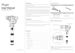
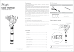
W
W
L
BI series temperature controller user manual
型号
40 mm
H
Features:
3 digit dual display
SV value set by key, one key for one digit
Easy operation and long use life
Fuzzy PID control output
Economic for simple control
1.Ordering code
BI 7 - R -K
Input signal
K:K type
Output R:relay output
P:PT100
Q:SSR output
W
4 0 mm
℃
K:K Type input(range:0-600℃) P:PT100 Type input(range:0-600℃)
Input type
Display range E:E Type input(range:0-400℃) J:J Type input(range:0-600℃)
③
①
④
②
⑤
⑥
Resolution
0. 8% F .S
开 孔尺寸
a X b
BI 4
BI 6
4 8 X 48
9 6 X 49
4 5X 4 5 X 64
9 0X 4 5 X 63
4 5 . 6 X4 5 . 6
9 1 X 4 5. 6
BI7
72 X 7 2
65X65X63
6 6 X6 6
BI9
96 X 9 6
8 9 X 8 9X 6 3
9 0 X9 0
① :Measure value
②:Set value
③ :OUT indicate lamp
④ :AT
indicate lamp
⑤ :Set/Confirm key (SET)
⑥ :①②③ Increase key
5.Operating instructions
A: SV value setting process
Temperature setting
Cu:Cu50 Type input(range:0-150℃)
Deviation
壳 体尺寸
h X w X L
4.Panel instructions
Dimension 4:48H*48W 6:96H*48W
7:72H*72W 9:96H*96W
BI series intelligent temperature controller
2.Technical parameters
面板 尺寸
H X W
Press one of ①②③ keys, one of SV digit
flashing, each press the value keep increasing
Stop pressing when you set the value as you
want, after 4 flashings, the new SV set down.
±3 Di g i ti
1℃
Control mode PID control or ON/OFF control set by key
Control
output
Power
Ambient
temperature
Relay : AC250V3A
SSR: DC8-15V
AC 22 0V±2 0 %
0 -5 0℃
1 0 0—2 4 0V AC /D C (Customized)
4 5- 85 % (No freezing)
3.Mounting dimensions (mm)
Remarks:If the control temperature is not good, please start AT autotuning
function.(Press SET and No.3 key at the same time, AT lamp will be on)
PV value should not more than 80% of SV vaiue, otherwise autotuning run error.
For example, when the SV is100, the PV should less than 80.
B:Autotuning function
Autotuning starts by press SET and No.3 key, AT lamp on. And finished AT lamp
off. (All parameters can be modified only after autotuning finished.)
C:Parameters setting
In the measuring estate, Press and hold SET key for 5 seconds, enter parameter
setting area.
Heatr
Previous measured value
Press SET
Press SET
Press SET
Press SET
Press SET
(LCK key lock) Press 1.2.3 key to modify the mumber,then press
SET key to confirm. The factory setting is 55
When LCK=51,all the parameters are locked except SV and LCK value
WHen LCK=55,all the parameters can be modified
When LCK not 51/55,all the parameters are locked except LCK value
(Proportional Band) Press 1.2.3 key to modify the mumber,then press
SET key to confirm.Factory set is 0,Range is 0-600
P=0 means it is the position controll (ON/OFF).The larger the proportional band
is,the slower the system heats.Under this condition the time to reach SV
is longer.If the proportion temperature is too low,it will cause oscillation.
(Integral Time) Press 1.2.3 key to modify the mumber,then press
SET key to confirm.Factory set is 240,Range is 0-600
I=0 means that it is PD heating system.The smaller the integral time is,the
stronger the integral action is.And better for eliminating the bias between
it and the setting value.If the integral time is too short,it may cause oscillation.
(Integral Time) Press 1.2.3 key to modify the mumber,then press
SET key to confirm.Factory set is 60,Range is 0-600
D=0 means that it is PI heating system. To decrease the derivative
time to a proper value can prevent the system from oscillation.The
bigger the D is,the derivative action is.
(Hysteresis value) Press 1.2.3 key to modify the mumber,then press
SET key to confirm.Factory set is 3,Range is 1-50.If P not 3,it is unvalid.
When P=0,HYS=3,and SV IS 100
While the PV=100,it will stop heating,lower than 96,it will begin heating
Press SET
(Control cycle) Press 1.2.3 key to modify the mumber,then press
SET key to confirm.Factory set is 20,Range is 1-255.
Relay output:T=20 SSR output or SCR output:T=1
Press SET
(PV bias amend) Press 1.2.3 key to modify the mumber,then press
SET key to confirm.Factory set is 0,Range is -50~50.
PV bias applied to amend the bias caused by TC and compensation lead
during the measuring process
Terminal connection(Note:Please refer to the product connection drawing)
1
2
3
4
5
6
7
8
A C 22 0 V
NO
L
OUT C
H
NC
-
T.C
RB
+
A C 22 0 V
SSR
OUT
+
-
T.C
RB
+
1
2
3
4
5
6
7
8
A C 22 0 V
NO
L
OUT C
H
NC
T.C
RB
+
1
2
3
4
5
6
7 Blue
8 Red
AC220V
Heater Machinery
K type
Remarks:
1.Relay capacity: AC 3A/250V
2.SSR DC8-15V, Max 30mA
7.Caution
1.Installed in the following environments:
A:Atmospheric pressure:86-106Kpa,Ambient temperature:0-50 degree,Humidity:35%-85%(no freeze)
B:Dramtic changes in the ambient temperature may cause condensation,corrosive,flammable gases,
the main structure of direct vibration or shock water,oil,chemicals,smoke or steam excessive
dust pollution,salt or metal powders,air confitioning blowing straight direct sun,thermal
radiation accumulation place
C:Instrument should be stored in dry and ventilated,non-corrosive gas application with the
case of complete package
Press SET
(FT filter constant) Press 1.2.3 key to modify the mumber,then press
SET key to confirm.Factory set is 100,Range is 0-200.
The smaller the filter is,the quicker response but it caused fluctuations
Press SET
6.Connection drawing
Connection Caution
1.When input TC,should use the corresponding compensation lead.
2.Input signal wire should be far alway from other noice source to avoid interference.
3. Attention to Min/Max of the input T/C, Wrong connect probably cause burning out.
2.Warranty
A:Meter sold within one year from the data of billing,failure due to manufacturing quality
full warranty by the factory responsible for,damager caused by improper use of the repair
costs from the factory charge a fee
3.About Error
A:If the PV display "Err" or "HHH",it means it is out of range or TC/RTD does not work
B:If the parameters can not be changed,please chec if the LCK value is 55.
C:The PV value display abnormal fluctuations, please increase the parameter FT value.