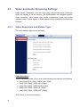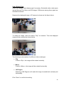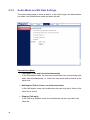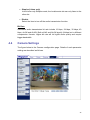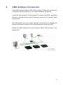
1
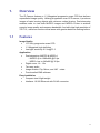
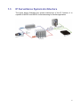
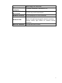
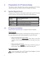
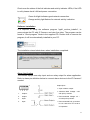
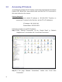
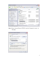
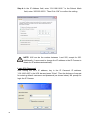
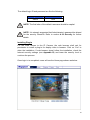
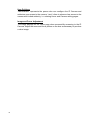
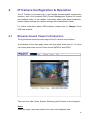
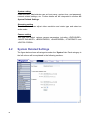
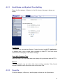
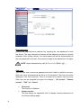
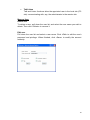
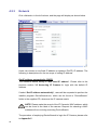
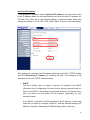
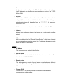
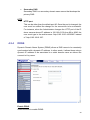
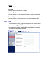
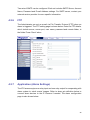
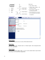
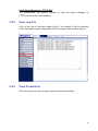
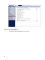
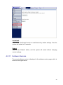
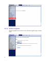
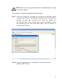
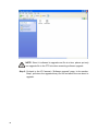
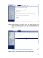
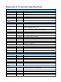
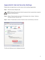
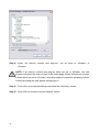
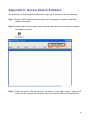
1.3 Megapixel IP Camera
User Manual
00P3H060MZSEA1-01
Table of Contents
1.
Overview .....................................................................................................................3
1.1
Features.............................................................................................................3
1.2
Package Contents..............................................................................................4
1.3
IP Surveillance System Architecture ..................................................................5
2.
Introduction of IP Camera..........................................................................................6
2.1
Camera Dimensions ..........................................................................................6
2.2
Connectors on the Rear Board ..........................................................................6
3.
Preparations for IP Camera Setup ............................................................................8
3.1
System Requirements........................................................................................8
3.2
IP Camera Installation........................................................................................8
3.3
Accessing IP Camera ......................................................................................10
4.
IP Camera Configuration & Operation ....................................................................15
4.1
Browser-based Viewer Introduction .................................................................15
4.2
System Related Settings..................................................................................16
4.2.1
Host Name and System Time Setting................................................17
4.2.2
Security..............................................................................................17
4.2.3
Network .............................................................................................20
4.2.4
DDNS ................................................................................................23
4.2.5
Mail ....................................................................................................24
4.2.6
FTP....................................................................................................25
4.2.7
Application (Alarm Settings) ..............................................................25
4.2.8
View Log File .....................................................................................27
4.3
4.4
4.2.9
View Parameters ...............................................................................27
4.2.10 Factory Default ..................................................................................28
4.2.11 Software Version ...............................................................................29
4.2.12 Software Upgrade..............................................................................30
Video and Audio Streaming Settings ...............................................................34
4.3.1
Video Resolution and Rotate Type ....................................................34
4.3.2
Audio Mode and Bit Rate Settings .....................................................36
Camera Settings ..............................................................................................37
4.4.1
Exposure Setting ...............................................................................38
4.4.2
White Balance Setting .......................................................................38
4.4.3
Brightness Setting..............................................................................39
4.4.4
Sharpness Setting .............................................................................39
4.4.5
Contrast Setting .................................................................................40
4.4.6
Digital Zoom Setting ..........................................................................40
5. CMS Software Introduction......................................................................................41
Appendix A: Technical Specifications ...........................................................................42
1
Appendix B: Internet Security Settings .........................................................................43
Appendix C: Device Search Software ............................................................................45
2
1.
Overview
The IP Camera features a 1.3 Megapixel progressive scan CCD that delivers
unparalleled image quality. Utilizing progressive scan CCD sensor, it produces
images of rapid moving objects with minimum motion blurring. Dual streaming
enables users to view both MJPEG images and MPEG-4 video to achieve
superior image quality and conserve bandwidth. And with ultra high resolution of
700 TVL, users can monitor critical areas with greater detail like nothing before.
1.1
Features
Image Quality
•
1/3” Sony progressive scan CCD
•
1.3 Megapixel high definition
•
Low light sensitivity 0.2 [email protected]
Application
•
Dual streaming: MJPEG & MPEG-4
- MJPEG up to 1280x960 @15 fps
- MPEG-4 up to 640x480 @ 30 fps
•
Digital zoom: 1x ~ 12x
•
Two-way audio
•
Image rotation: Flip, Mirror, and 180∘rotate
•
Free bundled CMS software
Easy Installation
•
•
Compact size & light weight
Interface: 10/100 Ethernet with RJ-45 connector
3
1.2
Package Contents
Please check the package contains the following items listed below.
1.3 Megapixel IP Camera
Alarm I/O terminal block
DC12V Power Adaptor
(DC model only)
CD
(bundled software,
documentation)
4
C/CS mount lens adaptor
1.3
IP Surveillance System Architecture
The figure below illustrates the system architecture of the IP Camera. It is
capable of MJPEG and MPEG-4 dual streaming for flexible application.
5
2.
Introduction of IP Camera
This chapter will provide the camera dimensions for reference before installation.
Definition of each connector on the camera’s rear board will also be specified.
2.1
Camera Dimensions
VIDEO
DC
The IP Camera’s dimensions are shown as below.
DC12V
NETWORK
I/O
1 2 3 4
LINE
OUT
LINE IN
MIC IN
AUTO
IRIS
2.2
Connectors on the Rear Board
The diagram below shows the IP Camera’s rear board. Definition for each
connector will be given as follows.
Reset Button
VIDEO
DC
Power LED
DC12V
NETWORK
I/O
1 2 3 4
LINE
OUT
LINE IN
MIC IN
AUTO
IRIS
6
Connector
Definition
Power LED
Green link light indicates good power connection.
Reset button
For system reset
Press and hold the Reset button to restore factory
default settings.
DC12V connector
DC 12V power connection
Video/DC switch
For Video drive lens/DC drive lens. Set the switch to
“Video” if use a video drive lens, and set it to “DC”
when using a DC drive lens.
I/O terminal
connector
For alarm connection (see section 3.2)
Line Out & Line In /
Mic In ports
For two-way audio transmission
Network connector
RJ-45 connector for LAN connection
Network LEDs
Link and activity
Green link light indicates good network connection
Orange activity light flashes for network activity
indication.
Auto iris connector
For use with auto iris lens
7
3.
Preparations for IP Camera Setup
This chapter outlines information about system requirements for IP Camera
operation, procedures of camera connection, and login to the camera.
3.1
System Requirements
To perform the IP Camera via web browser, please ensure your PC is in good
network connection, and meet system requirement as described below.
3.2
Items
Minimum Requirement
Personal
Pentium-III 600MHz processor
Computer
RAM 256 MB
Operating System
Windows 2003, XP
Web Browser
Microsoft Internet Explorer 6.0 or above
Network Card
10Base-T (10 Mbps) or 100Base-TX (100 Mbps) operation
Viewer
ActiveX control plug-in for Microsoft IE
IP Camera Installation
Please follow the instructions below to complete IP Camera installation.
Cable Connection
Use of Category 5 Ethernet cable is recommended for network connection; to
have best transmission quality, cable length shall not exceed 100 meters.
•
When connecting through a hub or switch:
Connect one end of a straight through CAT5 cable to the RJ-45
connector of the IP camera, and the other end of the cable to the hub or
switch.
•
When connecting to PC directly:
Connect one end of a crossover CAT5 cable to the RJ-45 connector of
the IP camera. Then connect the other end of the cable to PC.
Power up the Camera
Connect the power jack to the IP Camera before plugging in to power
socket, to avoid danger of electric shock.
8
Check over the status of the link indicator and activity indicator LEDs; if the LED
is unlit, please check LAN and power connection.
Green link light indicates good network connection.
Orange activity light flashes for network activity indication.
Software Installation
It is required to setup the software program “ipp41_runtime_installer”, to
communicate the PC with IP Camera, and view live video. The program can be
found in “Client program” folder in the supplied CD. Double click to execute the
program; it will be automatically installed to your PC.
The installation wizard shuts down when installation completed.
Alarm Application
The camera equips one relay input and one relay output for alarm application.
Refer to alarm pin definition below to connect alarm devices to the IP Camera if
needed.
Output Spec.:
• Open collector output
1 2 3 4
1.
Output+
2.
Output-
3.
Input+
4.
Input-
• Absolute MAX Voltage: 5.5V
with pull-up resistor
• Recommended Voltage: 3V ~
5V with pull-up resistor
• Recommended Pull up resistor
is 1.8k~100k Ω for TTL Level at
5V operation.
9
3.3
Accessing IP Camera
To access and configure the IP Camera, users simply login through the Internet
Explorer (IE). Before that, users should make sure that the PC is connected to
the same network as the camera.
Camera Default IP
The IP Camera’s default IP address is: 192.168.0.250. Therefore, to
access the IP camera for the first time, set the PC’s IP address as:
IP Address: 192.168.0.XXX
Subnet Mask: 255.255.255.0
Follow the procedure to set PC IP address.
Step 1: Enter “Network Connections” on the “Control Panel” or “Network
Neighborhood”, and double click “Local Area Connections.”
Step 2: In the page “Network Connections,” double click “Local Area
Connection.”
10
Step 3: Select “Internet Protocol (TCP/IP)” and click “Properties” to enter its
sub-page.
11
Step 4: In the IP Address field, enter “192.168.0.XXX.” In the Subnet Mask
field, enter “255.255.255.0.” Then Click “OK” to confirm the setting.
NOTE: XXX can be the number between 1 and 255, except for 250.
Additionally, if users want to change the IP address or the IP Camera to
obtain the IP address automatically.
Login ID & Password
After setting the PC’s IP address, key in the IP Camera’s IP address:
“192.168.0.250” in the URL bar and press “Enter”. Then the dialogue of request
for entering default username and password (as shown below) will prompt for
login the IP Camera.
12
The default login ID and password are like the following:
Login ID
Password
Admin
1234
NOTE: The first letter of the default username should be capital.
NOTE: It is strongly suggested that Administrator’s password be altered
for the security concerns. Refer to section 4.2.2 Security for further
details.
Installing Plug-in
For the initial access to the IP Camera, the web browser shall ask for
permission to install a plug-in for display video in browser. Click on “Yes” to
allow the installation. If web browser doesn’t allow the installation, check the
Internet security settings (see Appendix B) and lower the security level to
continue the process.
Once login in is completed, users will see the Home page shown as below:
13
User Privilege
“Administrator” represents the person who can configure the IP Camera and
authorize user access to the camera; “user” refers to whoever has access to the
camera with limited authority, i.e. entering Home and Camera setting pages.
Image and Focus Adjustment
The image displays on the Home page when successfully accessing to the IP
Camera. Adjust the zoom and focus pullers on the lens as necessary to produce
a clear image.
14
4.
IP Camera Configuration & Operation
The IP Camera is provided with a user-friendly browser-based configuration
interface, and a free bundled CMS (Central Management System) for record
and playback video. In this chapter, information about main page introduction,
system related settings and camera settings will be described in detail.
For further information about CMS software, please refer to Chapter 5 and
CMS user manual.
4.1
Browser-based Viewer Introduction
The figure below shows the main page of the IP Camera user interface.
At the bottom of the main page, users can also adjust video size (x1, x1/2 and
full screen) and select a kind of video format (MPEG-4 and JPEG).
There are four tabs: Home, System, Streaming and Camera, on the top panel.
Home
Under the page, users can monitor live video of the targeted area.
15
System setting
Under the item, Administrator can set host name, system time, root password,
network related settings, etc. Further details will be interpreted in section 4.2
System Related Settings.
Streaming setting
The Administrator can adjust video resolution and rotate type and select an
audio mode.
Camera setting
The user can adjust various camera parameters, including <EXPOSURE>,
<WHITE BALANCE>, <BRIGHTNESS>, <SHARPNESS>, <CONTRAST> and
<DIGITAL ZOOM>.
4.2
System Related Settings
The figure below shows all categories under the “System” tab. Each category in
the left column will be explained in the following sections.
16
4.2.1
Host Name and System Time Setting
Press the first category: <System> in the left column; the page is shown as
below.
Host Name
The name is for camera identification. If alarm function (see 4.2.7 Application)
is enabled and is set to send alarm message by Mail/FTP, the host name
entered here will display in the alarm message.
Sync With Computer Time
Select the item, and video date and time display will synchronize with the PC’s.
Manual
The Administrator can set video date, time and day manually. Entry format
should be identical with that shown next to the enter field.
4.2.2
Security
Click the category: <Security>, and the page is shown as the figure below.
17
Root password
Change the Administrator’s password by inputting the new password in both
text boxes. The input characters/numbers will be displayed as dots for security
purposes. After clicking <Save>, the web browser will ask the Administrator for
the new password for access. The maximum length of the password is 14 digits.
NOTE: these characters are valid: A-Z, a-z, 0-9, !#$%&’-.@^_~
Add user
Type the new user's name and password and click <Add> to add the new user.
Both user name and password can be up to 16 characters. The new user will be
displayed in the user name list. There is a maximum of twenty user accounts.
Each user can be assigned four types of privileges – “I/O access”, “Camera
control”, “Talk” and “Listen”.
18
•
I/O access
This function is disabled.
•
Camera control
This item allows the appointed User to change camera parameters on
the Camera Setting page.
•
Talk/Listen
Talk and Listen functions allow the appointed user in the local site (PC
site) communicating with, say, the administrator in the remote site.
Manage User
Delete user
To delete a user, pull down the user list, and select the user name you wish to
delete. Then click <Delete> to remove it.
Edit user
Pull down the user list and select a user name. Click <Edit> to edit the user’s
password and privilege. When finished, click <Save> to modify the account
authority.
19
4.2.3
Network
Click <Network> in the left column, and the page will display as shown below.
Users can choose to use fixed IP address or dynamic (DHCP) IP address. The
following is descriptions for the two ways of setting IP address.
Get IP address automatically (DHCP)
The camera’s default setting is “Use fixed IP address”. Please refer to the
previous section 3.3 Accessing IP Camera for login with the default IP
address.
If select “Get IP address automatically”, users will be requested to perform the
installer program: DeviceSearch.exe, which can be found in “DeviceSearch”
folder in the supplied CD, whenever the IP camera resets.
NOTE: Please make the record of the IP Camera’s MAC address, which
can be found in the label of the camera. Request for selecting a MAC
address will occur during executing DeviceSearch.
The procedure of employing DeviceSearch to login the IP Camera, please refer
to Appendix C.
20
Use fixed IP address
To setup static IP address, select “Use fixed IP address” and move the cursor
to the IP address blank (as indicated below) and insert the new IP address, ex.
192.168.7.250; then go to the Default gateway (explained latter) blank and
change the setting, ex. 192.168.7.254. Press “Save” to confirm the new setting.
After setting the camera’s new IP address, please go to the PC’s TCP/IP setting
(see 3.3 Accessing IP Camera) for resetting as well. The following is the
descriptions for each TCP/IP related setting.
• DHCP
This item allows users to obtain a dynamic IP address from DHCP
(Dynamic Host Configuration Protocol) server during camera boots up.
When using DHCP, the settings are dynamic and they will change every
time you power up and power off the camera, depending on your
network's setup.
If use DHCP, a dynamic IP will be assigned to the IP camera. In this case,
users do not need to configure a static IP, and the Ethernet settings (IP
address, Netmask, Gateway and DNS settings) will be read only.
21
• IP
The item is used to configure the PC’s IP (Internet Protocol) address.
The IP address is the identifier for your computer or device on a TCP/IP
LAN or WAN.
• Netmask
A Netmask is a 32-bit mask used to divide an IP address into subnets
and specify the networks available hosts. Its value is defined by your
network administrator. It takes the form as ***.***.***.***, for example,
255.255.255.255.
This item allows users to input the value of the Netmask for the PC.
• Gateway
Gateway is a node on a network that serves as an entrance to another
network.
• DNS
DNS is the abbreviation for “Domain Name System”, which is an Internet
service that translates domain names into IP addresses because domain
names are easier to remember.
General
22
•
IP address
This is necessary for network identification.
•
Subnet mask
It is used to determine if the destination is in the same subnet. The
default value is “255.255.255.0”.
•
Default router
This is the gateway used to forward frames to destinations in different
subnet. Invalid router setting will fail the transmission to destinations in
different subnet.
•
Primary DNS
Primary DNS is the primary domain name server that translates
hostnames into IP addresses.
•
Secondary DNS
Secondary DNS is a secondary domain name server that backups the
primary DNS.
HTTP
•
4.2.4
HTTP port
This can be other than the default port 80. Once the port is changed, the
user must be notified the change for the connection to be successful.
For instance, when the Administrator changes the HTTP port of the IP
dome camera whose IP address is 192.168.0.100 from 80 to 8080, the
user must type in the web browser “http://192.168.0.100:8080” instead
of “http://192.168.0.100”.
DDNS
Dynamic Domain Name System (DDNS) allows a DNS name to be constantly
synchronized with a dynamic IP address. In other words, it allows those using a
dynamic IP address to be associated to a static domain name so others can
connect to it by name.
Enable DDNS
Check the item to enable DDNS.
23
Provider
Select one DDNS host from the provider list.
Host name
Enter the registered domain name in the field.
Username/E-mail
Enter the username or e-mail required by the DDNS provider for authentication.
Password/Key
Enter the password or key required by the DDNS provider for authentication.
4.2.5
Mail
The Administrator can set as e-mail via Simple Mail Transfer Protocol (SMTP)
when an alarm is triggered. SMTP is a protocol for sending e-mail messages
between servers. SMTP is a relatively simple, text-based protocol, where one or
more recipients of a message are specified and the message text is transferred.
The configuration page is shown as follows:
24
Two sets of SMTP can be configured. Each set includes SMTP Server, Account
Name, Password and E-mail Address settings. For SMTP server, contact your
network service provider for more specific information.
4.2.6
FTP
The Administrator can set as e-mail via File Transfer Protocol (FTP) when an
alarm is triggered. The FTP setting page is shown below. Enter the FTP details,
which include server, server port, user name, password and remote folder, in
the fields. Press “Save” when
4.2.7
Application (Alarm Settings)
The IP Camera equips one relay input and one relay output for cooperating with
alarm system to catch events’ images. Refer to alarm pin definition below to
connect alarm devices to the IP Camera if needed. The alarm configuration
page is also shown below.
25
Output Spec.:
• Open collector output
1 2 3 4
1.
Output+
2.
Output-
3.
Input+
4.
Input-
• Absolute MAX Voltage: 5.5V
with pull-up resistor
• Recommended Voltage: 3V ~
5V with pull-up resistor
• Recommended Pull up resistor
is 1.8k~100k Ω for TTL Level at
5V operation.
Alarm Switch
The Administrator can turn on or turn off the alarm function.
Alarm Type
Select an alarm type, “Normal close” or “Normal open,” that corresponds with
the alarm application.
Alarm Output
Define alarm output signal “high” or “low” as the normal alarm output status
according to the current alarm application.
26
Send Alarm Message by FTP/E-Mail
The Administrator can specify whether to send the alarm message by
FTP/E-mail when an event happens.
4.2.8
View Log File
Click on the link to view the system log file. The content of the file provides
useful information about configuration and connections after system boot-up.
4.2.9
View Parameters
Click on this item to view the entire system’s parameter setting.
27
4.2.10 Factory Default
The factory default setting page is shown as below.
28
Set Default
Click on the “Set Default” button to recall the factory default settings. Then the
system will restart in 30 seconds.
Reboot
Click on the “Reboot” button, and the system will restart without changing
current settings.
4.2.11 Software Version
The current software version is displayed in the software version page, which is
shown as the figure below.
29
4.2.12 Software Upgrade
Software upgrade can be carried out in the “Software Upgrade” page, as shown
below.
30
NOTE: Make sure the upgrade software file is available before carrying
out software upgrade.
The procedure of software upgrade is like the following:
Step 1: Type the IP Camera’s FTP address in the URL bar of the Web browser
to login to the FTP site. The address is identical to the IP Camera’s IP
address; the prefix ftp:// should be set before the address, ex.
ftp://192.168.7.250. Then enter the User name and password, which
are identical with the ones used when login to the IP Camera, to
connect to the FTP site.
Step 2: Copy the upgrade file, ex. userland.jffs2, from the source and
paste it to the FTP site.
31
NOTE: Since it is allowed to upgrade one file at a time, please put only
one upgrade file in the FTP site when executing software upgrade.
Step 3: Go back to the IP Camera’s “Software upgrade” page. In the section:
Step1, pull down the upgrade binary file list and select the one about to
upgrade.
32
Step 4: Press “Upgrade” in the section: Step3. The system will then check
whether the upgrade file exists or not. Then the upgrade status bar will
display on the page. When it runs to 100%, the upgrade process is
finished.
Step 5: Close the Web browser and login to the IP Camera again.
33
4.3
Video and Audio Streaming Settings
Press the tab ”Streaming” in the top of the page, and the two items: Video and
Audio will display in the left column. The Administrator can configure specific
video resolution, video rotate type, audio transmission mode and audio
streaming here. Further details of these settings will be specified in the following
sections.
4.3.1
Video Resolution and Rotate Type
The video setting page is show as below:
Video Resolution
The IP Camera provides various video dual streaming formats like the following:
•
•
•
•
Jpeg Quad VGA (15fps) + MP4 VGA (15fps)
Jpeg VGA (30fps) + MP4 VGA (30fps)
Jpeg VGA (30fps) + MP4 QVGA (30fps)
Jpeg VGA (30fps) + MP4 CIF (30fps)
• Jpeg VGA (30fps) + MP4 QCIF (30fps)
Click “Save” to confirm the setting.
34
Video Rotate Type
Users can change video display type if necessary. Selectable video rotate types
include Normal, Flip, Mirror and 180 degree. Differences among these types are
illustrated as below.
Suppose the displayed image of IP camera is shown as the figure below.
To rotate the image, users can select “Flip”, for instance. Then the displayed
image will be reversed as shown below.
The following is descriptions for different video rotate type.
• Flip
If select <Flip>, the image will be rotated vertically.
• Mirror
If select <Mirror>, the image will be rotated horizontally.
• 180 Degree
Selecting <180 Degree> will make the image inversed both vertically and
horizontally.
Click “Save” to confirm the setting.
35
4.3.2
Audio Mode and Bit Rate Settings
The audio setting page is show as below. In the Audio page, the Administrator
can select one transmission mode and audio bit rate.
Transmission Mode
• Full-duplex (Talk and Listen simultaneously)
In the Full-duplex mode, the local and remote sites can communicate with
each other simultaneously, i.e. both sites can speak and be heard at the
same time.
• Half-duplex (Talk or Listen, not at the same time)
In the Half-duplex mode, the local/remote site can only talk or listen to the
other site at a time.
• Simplex (Talk only)
In the Talk only Simplex mode, the local/remote site can only talk to the
other site.
36
• Simplex (Listen only)
In the Listen only Simplex mode, the local/remote site can only listen to the
other site.
• Disable
Select the item to turn off the audio transmission function.
Bit Rate
Selectable audio transmission bit rate include 16 kbps, 24 kbps, 32 kbps, 40
kbps, uLAW and ALAW. Both uLAW and ALAW signify 64 kbps but in different
compression formats. Higher bit rate will let higher audio quality and require
bigger bandwidth.
4.4
Camera Settings
The figure below is the Camera configuration page. Details of each parameter
setting are described as follows.
37
4.4.1
Exposure Setting
The exposure is the amount of light received by the image sensor and is
determined by the width of lens diaphragm opening (iris adjustment), the
amount of exposure by the sensor (shutter speed) and other exposure
parameters. With this item, users can define how the Auto Exposure function
works.
Two modes, Auto Mode and Manual Mode, are available.
Auto Mode
In this mode, the camera’s Brightness, Shutter Speed, IRIS and AGC (Auto
Gain Control) control circuits work together automatically to get consistent video
output level.
Manual Mode
In this mode, users can select a number between 1 and 11, which represents
shutter speed ranging from 1/4 to 1/10000 sec; bigger number means slower
shutter. Once change the setting, press <SET> to confirm the new setting.
4.4.2
White Balance Setting
A digital camera needs to find reference color temperature, which is a way of
measuring the quality of a light source, for calculating all the other colors. The
unit for measuring this ratio is in degree Kelvin (K). Users can select one of the
White Balance Control modes according to the operating environment. The
following table shows the color temperature of some light sources.
38
Light Sources
Color Temperature in K
Cloudy Sky
Noon Sun and Clear Sky
Household Lighting
75-watt Bulb
Candle Flame
6,000 to 8,000
6,500
2,500 to 3,000
2,820
1,200 to 1,500
Auto Mode
In this mode, white balance works within its color temperature range and
calculates the best-fit white balance.
Indoor/outdoor Mode
Select for indoor or outdoor mode.
Manual Mode
In this mode, users can change the White Balance value manually. Users can
select a number between 1 ~ 11, and press <SET> to confirm the new setting.
4.4.3
Brightness Setting
Users can adjust the image’s brightness by adjusting the item. To increase
video brightness, select a bigger number. Press <SET> to confirm the new
setting.
4.4.4
Sharpness Setting
Increasing the sharpness level can make the image looked sharper; especially
enhance the object’s edge. Press <SET> to confirm the new setting.
39
4.4.5
Contrast Setting
Camera image contrast level is adjustable; please select ranging from 1 to 11.
4.4.6
Digital Zoom Setting
The camera’s digital zoom is adjustable from x1 to x12 at VGA resolution. Press
<SET> to confirm the new setting.
40
5.
CMS Software Introduction
Central Management System (CMS) offers a powerful interface for a simple and
centralized monitoring solution of your video surveillance equipments.
It gives the user access to monitor multiple IP cameras and DVRs, and allows
the user to simultaneously monitor 64 sites per group (up to 10 groups) within
several clicks.
One administrator and up to 3 users (depends on the product you bought) are
allowed to access the remote DVR unit simultaneously through the CMS.
Please find CMS software and its user manual in folder “CMS software” in the
attached CD.
41
Appendix A: Technical Specifications
Camera
Image Sensor
⅓" Sony progressive CCD
Picture Elements
1280(H) x 960 (V), 1.3M CCD
Resolution
>700 TVL
Minimum Illumination
0.2 lux @ F1.2
Shutter Speed
1/4 ~ 1/10000 sec.
White Balance
Manual / ATW (1500 ~ 15000K)
Lens
Video drive & DC drive (selectable)
Operation
Video Compression
MPEG-4 / MJPEG
Video Streaming
Simultaneous MPEG-4 and MJPEG video stream (dual stream)
Resolution
MPEG-4: VGA, QVGA, CIF, QCIF
MJPEG: 1280x960(4 VGA), VGA
Frame Rate
Image Setting
MPEG-4 30fps@VGA, MJPEG 15fps@1280x960
Brightness
Manual
Exposure
Auto / Manual
Sharpness
Manual
Contrast
Manual
White Balance Auto / Manual / Indoor / Outdoor
Digital Zoom
1x ~ 12x
Rotation
Flip, Mirror, and 180∘Rotate
Audio
Line out, Line in/mic in
Alarm
1 Relay In, 1 Relay Out
Network
Interface
10/100 Ethernet (RJ-45)
Protocol
IP, TCP, UDP, ICMP, FTP, SMTP, DHCP, HTTP, Telnet and IGMP
Password Levels
User and Administrator
Internet Browser
Internet Explorer (6.0+)
User Account
20
Mechanical
Lens Mounting
Connectors
C or CS Mount
Power
DC Jack
Ethernet
RJ-45
Audio
Stereo phone jack, ∅ 3.5mm
Alarm
4 pins terminal block, pitch 3.5mm
Video drive & DC drive
Auto Iris
LED Indicator
Power, Link, ACT
General
Operating
Temperature
0°C ~ 50°C
Humidity: 10% to 90%, no condensation
Power Source
DC12V
Power Consumption
4.2W (max. 350mA@DC12V)
Certificate
Dimension
CE, FCC, RoHS compliant
125 x 70 x 52 mm (L x W x H) (w/o lens)
42
Appendix B: Internet Security Settings
Please follow the steps below to set the Internet security settings appropriately.
Step 1: Start the Internet Explorer (IE).
NOTE: Windows IE provides the ActiveX component that is required when using the
programs mentioned above.
Step 2: Select <Tools> from the main menu of the browser, then <Internet Options>,
and then click the <Security> tab.
Step 3: Select <Trusted sites> and click <Custom Level> in the Security Level area.
The Security Settings screen is displayed as below:
43
Step 4: Under “All ActiveX controls and plug-ins”, set all items to <Enable> or
<Prompt>.
NOTE: If all ActiveX controls and plug-ins items are set to <Enable>, the web
browser will permit the user to login in the Home page directly without any request.
If these items are set to <Prompt>, several prompts of request for accepting ActiveX
controls and plug-ins shall appear during login in.
Step 5: Click <OK> to accept the settings and close the <Security> screen.
Step 6: Click <OK> to close the Internet Options screen.
44
Appendix C: Device Search Software
The procedure of employing DeviceSearch to login the IP Camera is like the following:
Step 1: Select “Get IP address automatically, and the message of system restart will
display in the page.
Step 2: Double click on the program Device Search.exe (see the icon below); its window
will appear as below.
Step 3: Press the button “Device Search”, as shown in the figure above. Then all IP
devices in the network will be listed in the zone down the Device Search button.
45
Step 4: Check the IP Camera’s MAC address; then select the IP address followed with the
designate MAC. Double click or right click and select “Browse” to connect with the
camera directly via web browser.
Step 5: The dialogue of requesting for entering User name and Password should pop out.
Enter the correct user name and password to login in the IP Camera.
46