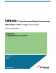
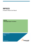
1
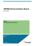
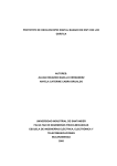
Targeting 56F8300
Demonstration Board
User Manual
56F800
16-bit Digital Signal Controllers
MC56F8300TUM
Rev. 4
08/2005
freescale.com
TABLE OF CONTENTS
About This Book v
Audience . . . . . . . . . . . . . . . . . . . . . . . . . . . . . . . . . . . . . . . . . . . . . . . . . . . . . . . . . v
Organization . . . . . . . . . . . . . . . . . . . . . . . . . . . . . . . . . . . . . . . . . . . . . . . . . . . . . . v
Suggested Reading . . . . . . . . . . . . . . . . . . . . . . . . . . . . . . . . . . . . . . . . . . . . . . . . v
Conventions . . . . . . . . . . . . . . . . . . . . . . . . . . . . . . . . . . . . . . . . . . . . . . . . . . . . . vi
Definitions, Acronyms, and Abbreviations . . . . . . . . . . . . . . . . . . . . . . . . . . . . . . vii
References . . . . . . . . . . . . . . . . . . . . . . . . . . . . . . . . . . . . . . . . . . . . . . . . . . . . . . vii
Chapter 1
Introduction
1.1
Overview . . . . . . . . . . . . . . . . . . . . . . . . . . . . . . . . . . . . . . . . . . . . . . . . . . 1-1
Chapter 2
56F8300 Demonstration Board Applications
2.1
Applications. . . . . . . . . . . . . . . . . . . . . . . . . . . . . . . . . . . . . . . . . . . . . . . .
2.1.1
Voice Recorder Demonstration . . . . . . . . . . . . . . . . . . . . . . . . . . . . . .
2.1.1.1
Set-up for Voice Recorder Demonstration . . . . . . . . . . . . . . . . . . .
2.1.1.2
Procedure for Voice Recorder Demonstration . . . . . . . . . . . . . . . .
2.1.2
E-field Demonstration . . . . . . . . . . . . . . . . . . . . . . . . . . . . . . . . . . . . .
2.1.2.1
Set-up for E-field Demonstration . . . . . . . . . . . . . . . . . . . . . . . . . .
2.1.2.2
Procedure for E-field Demonstration . . . . . . . . . . . . . . . . . . . . . . .
2.1.3
Temperature Sensor Demonstration . . . . . . . . . . . . . . . . . . . . . . . . . .
2.1.3.1
Procedure for Temperature Sensor Demonstration . . . . . . . . . . . .
2.1.4
CPU Utilization Demonstration . . . . . . . . . . . . . . . . . . . . . . . . . . . . . .
2.1.4.1
Procedure for CPU Utilization Demonstration . . . . . . . . . . . . . . . .
2.1.5
LED Demonstration . . . . . . . . . . . . . . . . . . . . . . . . . . . . . . . . . . . . . . .
2.1.5.1
Set-up for LED Demonstration . . . . . . . . . . . . . . . . . . . . . . . . . . . .
2.1.5.2
Procedure for LED Demonstration . . . . . . . . . . . . . . . . . . . . . . . . .
2.1.6
Fast Interrupt Demonstration . . . . . . . . . . . . . . . . . . . . . . . . . . . . . . . .
2.1.6.1
Set-up for Fast Interrupt Demonstration. . . . . . . . . . . . . . . . . . . . .
2.1.6.2
Procedure for Fast Interrupt Demonstration. . . . . . . . . . . . . . . . . .
2-1
2-1
2-2
2-2
2-3
2-3
2-3
2-4
2-5
2-5
2-6
2-7
2-8
2-8
2-8
2-8
2-9
Appendix A
Targeting 56F8300 Demonstration Board Schematics
Table of Contents, Rev. 4
Freescale Semiconductor
Preliminary
i
Targeting 56F8300 Demonstration Board, Rev. 4
ii
Freescale Semiconductor
Preliminary
LIST OF FIGURES
1-1
2-1
2-2
2-3
2-4
2-5
2-6
2-7
Select Code Design . . . . . . . . . . . . . . . . . . . . . . . . . . . . . . . . . . . . . . . .
Voice Recorder Demo Button Usage . . . . . . . . . . . . . . . . . . . . . . . . . . .
Voice Recorder Demo LED Usage. . . . . . . . . . . . . . . . . . . . . . . . . . . . .
E-Field Demo LED usage. . . . . . . . . . . . . . . . . . . . . . . . . . . . . . . . . . . .
Temperature Sensor Demo LED usage . . . . . . . . . . . . . . . . . . . . . . . . .
CPU Utilization LED usage . . . . . . . . . . . . . . . . . . . . . . . . . . . . . . . . . .
Editing Preferences . . . . . . . . . . . . . . . . . . . . . . . . . . . . . . . . . . . . . . . .
LED Demo LED usage . . . . . . . . . . . . . . . . . . . . . . . . . . . . . . . . . . . . . .
1-2
2-2
2-2
2-3
2-4
2-6
2-7
2-8
List of Figures, Rev. 4
Freescale Semiconductor
Preliminary
iii
Targeting 56F8300 Demonstration Board, Rev. 4
iv
Freescale Semiconductor
Preliminary
About This Book
This manual describes the applications for the 56F8300 Demonstration Board.
Audience
This document targets software developers using the 56F8300 Demonstration Board.
Organization
•
•
•
Chapter 1, Introduction—provides a brief overview of this document
Chapter 2, 56F8300 Demonstration Board Applications—describes the
available demonstrations for the 56F8300 Demonstration Board
Appendix A, Targeting 56F8300 Demonstration Board Schematics —contains
the schematics of the 56F8300 Demonstration Board
Suggested Reading
We recommend that you have a copy of the following references:
•
•
•
56F8323 Technical Data, MC56F8323
56F8300 Peripheral User Manual, MC56F8300UM
Inside CodeWarrior: Core Tools
Preface, Rev. 4
Freescale Semiconductor
Preliminary
v
Conventions
This document uses the following notational conventions:
Typeface,
Symbol or Term
Meaning
Examples
Courier
Monospaced
Type
Code examples
//Process command for line flash
Italic
Directory names,
project names,
calls,
functions,
statements,
procedures,
routines,
arguments,
file names,
applications,
variables,
directives,
code snippets
in text
...and contains these core directories:
applications contains applications software...
Bold
Reference sources,
paths,
emphasis
...refer to the 56F8300 Peripheral User Manual....
Blue Text
Linkable on-line
...refer to Chapter 7, License....
Number
Any number is considered a positive value,
unless preceded by a
minus symbol to signify
a negative value
3V
-10
DES-1
ALL CAPITAL
LETTERS
# defines/
defined constants
# define INCLUDE_STACK_CHECK
Brackets [...]
Function keys
...by pressing function key [F7]
Quotation
marks, “...”
Returned messages
...the message, “Test Passed” is displayed....
...CodeWarrior project, 3des.mcp is...
...the pConfig argument....
...defined in the C header file, aec.h....
...if unsuccessful for any reason, it will return
“NULL”...
Targeting 56F8300 Demonstration Board, Rev. 4
vi
Freescale Semiconductor
Preliminary
Definitions, Acronyms, and Abbreviations
The following list defines the acronyms and abbreviations used in this document. As this
template develops, this list will be generated from the document. As we develop more group
resources, these acronyms will be easily defined from a common acronym dictionary. Please
note that while the acronyms are in solid caps, terms in the definition should be initial capped
ONLY IF they are trademarked names or proper nouns.
ADC
Analog-to-Digital Converter
FFT
Fast Fourier Transform
FIR
Filter Interval Register
GPIO
General Purpose Input/Output
ISR
Interrupt Service Request
References
The following sources were used to produce this book:
1.
2.
3.
4.
5.
56F8300 Peripheral User Manual, MC56F8300UM
56F8300 Demonstration Board User’s Manual, MC56F8300DBUM
DSP56800E Reference Manual, DSP56F800ERM
56F8323 Technical Data, MC56F8323
56800/E Accelerated Development System Resource Pak CD-ROM (available
from the Literature Distribution Center)
Preface, Rev. 4
Freescale Semiconductor
Preliminary
vii
Targeting 56F8300 Demonstration Board, Rev. 4
viii
Freescale Semiconductor
Preliminary
Chapter 1
Introduction
1.1 Overview
The 56F8300 Demonstration Board is a low-cost board that allows a user to execute
preprogrammed demonstrations, as well as to develop his own applications using free
CodeWarrior tools. The 56F8300 Demonstration Board consists of a 60 MIPs 56F8323
controller; a microphone attached to the ADC; a speaker; an E-field sensor; two buttons
attached to external interrupts; and 10 LEDs. Pads have also been included on the
board so a user can access all of the 56F8323’s peripherals. The Demonstration Board
does not have an external crystal, so the 56F8323 must use its internal oscillator.
For more information about developing software for this demonstration board, please
refer to the 56F8300 Peripheral User Manual and 56F8323 Technical Data.
The software examples and source code for examples discussed in this document are
available on the “56800/E Accelerated Development System Resource Pak” CD-ROM,
which can be ordered from Motorola’s Literature Distribution Center.
All example projects on the CD utilize Processor ExpertTM (PE) The example projects
Suspend PE within CodeWarrior to save the PE state of the working projects. To enable
code design with PE within these projects, the following step is needed:
•
Within CodeWarrior under Processor Expert, select Code Design. See Figure 1-1.
This will enable Processor Expert for that project and allow a user to make
modifications to the project with PE.
Introduction, Rev. 4
Freescale Semiconductor
Preliminary
1-1
Introduction
Figure 1-1. Select Code Design
Targeting 56F8300 Demonstration Board, Rev. 4
1-2
Freescale Semiconductor
Preliminary
Chapter 2
56F8300 Demonstration Board
Applications
2.1 Applications
The following applications have been provided by Freescale to easily demonstrate some of the
features of the 56F8300 Series of controllers.
Applications developed for this demonstration board were not designed for the 56F8100
devices. The 56F8300 demonstration board does, however, fully support 56F8100 software
development.
2.1.1 Voice Recorder Demonstration
This demonstration exercises the ADC, TIMER, and GPIO in the 56F8323 processor. The
demonstration allows a user to record and play back seven seconds of voice. In addition, the
Voice Recorder Demonstration illustrates how the 56F8300 Series of controllers can be utilized
to:
6. Sample seven seconds of voice via the on-chip ADC peripheral and a microphone
7. Filter incoming samples with the FIR filter
8. Calculate the FFT of incoming voice samples and display frequency spectrum via LEDs
9. Encode incoming samples with the G.711 vocoder
10. Write encoded samples to the on-chip flash
11. Read encoded samples from the on-chip flash
12. Decode samples with the G.711 vocoder
13. Output voice samples via the on-chip timer (which generates PWM signal) to the speaker
56F8300 Demonstration Board Applications, Rev. 4
Freescale Semiconductor
Preliminary
2-1
56F8300 Demonstration Board Applications
Figure 2-1. Voice Recorder Demo Button Usage
Recording is ON
D10
D8
D6
D4
D2
High
Level
D9
D7
D5
D3
D1
Low
Level
4000Hz
3000Hz
2000Hz
1000Hz
0Hz
FFT Voice Analysis Display
Figure 2-2. Voice Recorder Demo LED Usage
2.1.1.1 Set-up for Voice Recorder Demonstration
Demonstration Board Jumper Settings:
Use default settings as shown in the 56F8300 Demonstration Board User’s Manual.
2.1.1.2 Procedure for Voice Recorder Demonstration
•
•
•
•
•
•
•
Install CodeWarrior project from the Resource Pak CD
Build and download the project; when the debugger reaches main(), it will stop
Select Run in the debugger to continue executing the demo
The IRQA button will be used to START recording voice; see Figure 2-1
The first row of five LEDs (D1, D3, D5, D7, and D9) will turn "ON" and "OFF", showing the
frequency spectrum of the incoming signal.; see Figure 2-2
Red LED D10 "ON" signifies that recording can start
Red LED D10 "OFF" signifies that recording has stopped
— The SW2 button will be used to play back the recorded voice; see Figure 2-1
•
The RESET button will reset the demo application
Targeting 56F8300 Demonstration Board, Rev. 4
2-2
Freescale Semiconductor
Preliminary
Applications
2.1.2 E-field Demonstration
This demonstration uses the on-board MC33794 E-Field Sensor as an input control for on-chip
generated audio tones, a CANNED message, and LED display. The application will utilize the
on-chip ADC module to monitor the MC33794 chip’s E1 sensor. Approaching the on-board E1
sensor pad will activate three tones, at 400Hz, 1KHz, and 2KHz. When a user touches the E1
pad sensor, a CANNED message, "ALERT", will be output. All tones and the CANNED
message will be generated and output by the 56F8323 processor. LEDs will also be activated
by the processor according to proximity to the E1 sensor pad.
Generated Tones:
2KHz
1KHz
400KHz
D10
D8
D6
D4
D2
D9
D7
D5
D3
D1
Figure 2-3. E-Field Demo LED usage
2.1.2.1 Set-up for E-field Demonstration
Demonstration Board Jumper Settings:
Use default settings as shown in the 56F8300 Demonstration Board User’s Manual.
2.1.2.2 Procedure for E-field Demonstration
•
•
•
•
•
Install CodeWarrior project from the Resource Pak CD
Build and download the project; when the debugger reaches main(), it will stop
Set the 56F8300 Demonstration Board on a flat surface
Select Run in the debugger to continue executing the demonstration
The 56F8300 Demonstration Board will then calibrate the E-Sensor’s surroundings
— The calibration will start with all LEDs on and gradually they will all turn off, at which point,
calibration is complete
— Tones will also be generated during the calibration process
•
Once the application is running, the application changes the ON/OFF state of the LEDs
and outputs one of three tones, depending upon proximity to E1 sensor pad
— A CANNED message, "ALERT", will be output when the E1 sensor pad is touched
•
The RESET button will reset the demo application
56F8300 Demonstration Board Applications, Rev. 4
Freescale Semiconductor
Preliminary
2-3
56F8300 Demonstration Board Applications
2.1.3 Temperature Sensor Demonstration
This demonstration exercises the Temperature Sensor, ADC, and GPIO in the 56F8323
processor.
The demo application samples the ADC input, ANA7, which is attached internally to the on-chip
Temperature Sensor. These samples are compared against a running dynamic threshold and a
pair of corresponding LEDs will be turned on. As the temperature in the processor increases,
the LED pairs, starting at D1/D2, will turn on until the last LED pair, D9/D10, is turned on . At this
point, the LED pair will roll over and start again at D1/D2. The reverse will happen when the
temperature of the processor decreases. See Figure 2-4.
D
As Temperature Increases
D10
D8
D6
D4
D2
D9
D7
D5
D3
D1
As Temperature Decreases
Figure 2-4. Temperature Sensor Demo LED usage
The temperature of the processor can be changed in many ways:
•
•
•
•
Heating the processor externally with a heat gun
Cooling the processor externally with cooling spray
Putting a finger on the processor
Pressing the IRQA button on the 56F8300 Demonstration Board
In the initial state of the demo application, all peripheral clocks are enabled and the ADC
Low-Power Mode (LPM) is disabled. By pressing the IRQA button, a user can toggle between
this state and a state where all peripheral clocks, except ADC and Timer A, are turned off, and
the ADC LPM is enabled.
Demonstration Board Jumper Settings:
Use default settings as shown in the 56F8300 Demonstration Board User’s Manual.
Targeting 56F8300 Demonstration Board, Rev. 4
2-4
Freescale Semiconductor
Preliminary
Applications
2.1.3.1 Procedure for Temperature Sensor Demonstration
•
•
•
•
Install CodeWarrior project from the Resource Pak CD
Build and download the project; when the debugger reaches main(), it will stop
Select Run in the debugger to continue executing the demonstration
The application starts with all peripheral clocks enabled and the ADC Low-Power Mode
(LPM) disabled.
— By pressing the IRQA button, a user can alter this internal configuration, and thus the internal
temperature of the processor, in the following ways:
1.Pressing the IRQA button after startup enables the LPM of the ADC and all
peripheral clocks, except for the ADC and Timer A, are disabled
2.Pressing the IRQA again disables the LPM of the ADC and re-enables all of the
peripheral clocks; the application is back to its initial state
•
Pressing the RESET button will reset the demo application
2.1.4 CPU Utilization Demonstration
This demonstration utilizes an RTOS, MicroC/OS-II by Jean J. Labrosse, to demonstrate CPU
utilization at different processor speeds.
The application starts out running at 60MHz and 60 MIPs, with 10 tasks running concurrently.
Each task utilizes six MIPs of the processor. This correlates to full CPU utilization at start-up.
Each task has an unique "priority" associated with it. Task 1 has the highest associated priority
and Task 10 has the lowest priority associated with it. There is also an LED for each task which
is toggled each time the task is run. At start-up, each task has the necessary bandwidth to
complete its six MIPs worth of tasks. As a result, 10 LEDs will be in an "ON" state; see
Figure 2-5.
The application allows a user to change the processor speed and thus the corresponding MIPs
by the IRQA button. After start-up, pressing the IRQA button drops the processor speed to
30MHz and 30 MIPs. At this point, the user will see that only the tasks with the top 5 priorities
have enough bandwidth to complete six MIPs worth of tasks; the tasks with the lower five
priorities do not. Pressing the IRQA button again drops the processor speed to 20MHz and 20
MIPs and the user will see that only the top three priority tasks will have enough bandwidth to
complete their six MIPs worth of tasks. Pressing the IRQA button again returns the application
to its original state of 60MHz and 60 MIPs with 10 LEDs "ON".
56F8300 Demonstration Board Applications, Rev. 4
Freescale Semiconductor
Preliminary
2-5
56F8300 Demonstration Board Applications
Task 1 LED (High Priority Task)
D10
D8
D6
D4
D2
D9
D7
D5
D3
D1
Task 10 LED (Lowest Priority Task)
Figure 2-5. CPU Utilization LED usage
Demonstration Board Jumper Settings:
Use default settings as shown in the 56F8300 Demonstration Board User’s Manual.
2.1.4.1 Procedure for CPU Utilization Demonstration
•
•
Install CodeWarrior project from the Resource Pak CD
Under Edit/Preferences, select Preferences
•
•
•
– This will then use the existing .elf (executable) file for the project
Select Run in the debugger to continue executing the demonstration
The application starts, running at 60MHz and 60 MIPs, with all 10 LEDs "ON"
By pressing the IRQA button, a user can change the processor’s speed and, thus, its
MIPs, in the following ways:
— Under Build Settings/Build before running, select Never; see Figure 2-6
1.Pressing the IRQA button after start-up drops the processor’s speed to 30MHz and
30 MIPs; only 5 LEDs will be in a constant "ON" state
2.Pressing the IRQA button again drops the processor speed to 20MHz and 20 MIPs; only
three LEDs will be in a constant "ON" state
3.Pressing the IRQA button again returns the application to its initial state
•
The RESET button will reset the demo application
Targeting 56F8300 Demonstration Board, Rev. 4
2-6
Freescale Semiconductor
Preliminary
Applications
Figure 2-6. Editing Preferences
To rebuild the .elf (executable) file, the build setting within CodeWarrior must be changed from
Never to Always and MicroC/OS-II source code must be added to the project. MicroC/OS-II
source code can be purchased at this URL: http://ucos-ii.com/.
2.1.5 LED Demonstration
The LED Demonstration illustrates the use of five channels of the Quad Timer. The first timer
goes off on a Compare1, which starts the second timer. The second timer goes off on Compare
2, which starts the third timer. The third timer goes off on Compare 3, which starts the fourth
timer, the fourth timer goes off on Compare4, which starts the fifth timer. The fifth timer goes off
on Compare 5, which starts the first timer. Each column of LEDs reflects the status of a
corresponding timer and each timer is set to run at .5 second intervals.
56F8300 Demonstration Board Applications, Rev. 4
Freescale Semiconductor
Preliminary
2-7
56F8300 Demonstration Board Applications
One column of LEDs displayed at a time
D10
D8
D6
D4
D2
D9
D7
D5
D3
D1
Figure 2-7. LED Demo LED usage
2.1.5.1 Set-up for LED Demonstration
Demonstration Board Jumper Settings:
Use default settings as shown in the 56F8300 Demonstration Board User’s Manual.
2.1.5.2 Procedure for LED Demonstration
•
•
•
•
•
Install CodeWarrior project from the Resource Pak CD
Build and download the project; when the debugger reaches main(), it will stop
Select Run in the debugger to continue executing the test
At this point, the five columns of LEDs will turn on and off sequentially
The RESET button will reset the demo application
2.1.6 Fast Interrupt Demonstration
The Fast Interrupt Demonstration illustrates the processing time saved when using a Fast
Interrupt over a Normal Interrupt. For one second, a timer interrupt will occur every 10ms and
will transfer a word from a modulo buffer to another buffer in RAM, using only registers available
to the Fast Interrupt’s automatic context switching. Results will then be printed to a Code
Warrior console window.
2.1.6.1 Set-up for Fast Interrupt Demonstration
Demonstration Board Jumper Settings:
Use default settings as shown in the 56F8300 Demonstration Board User’s Manual.
Targeting 56F8300 Demonstration Board, Rev. 4
2-8
Freescale Semiconductor
Preliminary
Applications
2.1.6.2 Procedure for Fast Interrupt Demonstration
•
•
•
•
Install CodeWarrior project from the Resource Pak CD
Build and download the project; when the debugger reaches main(), it will stop
Select Run in the debugger to continue executing the test
At this point, a console window will display the following information:
— Number of Idle Ticks in one second with "No Interrupts"
— Number of Idle Ticks in one second with "Normal Interrupts" and associated overhead
— Number of Idle Ticks in one second with "Fast Interrupts" and associated overhead
— How much more efficient the Fast Interrupt is than the Normal Interrupt
56F8300 Demonstration Board Applications, Rev. 4
Freescale Semiconductor
Preliminary
2-9
56F8300 Demonstration Board Applications
Targeting 56F8300 Demonstration Board, Rev. 4
2-10
Freescale Semiconductor
Preliminary
Appendix A
Targeting 56F8300 Demonstration
Board Schematics
Targeting 56F8300 Demonstration Board Schematics, Rev. 4
Freescale Semiconductor
Preliminary
A-1
Figure A-1. Targeting 56F8300 Demonstration Board
Targeting 56F8300 Demonstration Board, Rev. 4
A-2
Freescale Semiconductor
Preliminary
Figure A-2. Targeting 56F8300 Demonstration Board
Targeting 56F8300 Demonstration Board Schematics, Rev. 4
Freescale Semiconductor
Preliminary
A-3
POWER
1
POWER PORT
D11
PWR
SIGNAL
MC33794
9
5
R39
R38
E4
E3
C24 E2
E1
SCI1
C4
C10
14
1
3
R26
25
13
P1
R3
R54 R47 C41 R52
C37 R50
R8
R20
R10
C44
MOTOROLA
56F8300DEMO
GPIO /SERIAL
1
HEADSET
AXIOM MANUFACTURING
MC56F8300DEMO AXM-0319
SILKSCREEN-TOP
16
R63
10
R49
R60
C38
JP1 RC1
RS
1
D10 D9
D8 D7
D6 D5
D4 D3
D2 D1
JTAG
12
U13
R55
R51
R34
74ACT05
74ACT05
U2
U3
R48 U11
R7
R5
R9
R11
R6
C33
R32
9
R46 R53 C43 C42 C40 C39
C48
R4
LMV324
U10
C50
+3.3V
R22 JP2
R33
C54
74ACT00
R62
GND
2
TIMER /PWM
R28 R29
R35
U6 C49 C36 R45 R44 R43
R23 U4 +5V
C47
1
C34 C35 C32 R42
(NOTE: WAIT 10 SECONDS
AFTER POWER APPLIED
FOR CALIBRATION)
R13
C52
C13
FOR E-FIELD SENSOR
DEMONSTRATION
APPROACH WITH
YOUR HAND HERE
10
R14
MC56F8323
C51
74ACT125
1
C9 C14
C12
RESET IRQA
SW1
C11
R25
R27
U1
U5
C53
2
ADC
C8
R30
C46
CAN
L1
+
C7
R1
C3 SHIELD
GND
VDDA 1
1
Y1
R24 HOST
ENABLE
R31
E7
E5
C21
C18 11
R40
R16
VDDMON
R17
C22
C16
1
C15
4
C31 C30
C23
MICRO
C20
R15
8 C2
U7
PHONE
C5
R19 R18 R12
C1
2 C6 L2
74LCX125
LAMP_MON
LAMP_SNS
LAMPCTRL
RST
ISO_OUT
ISO_IN
ISO-9141
LAMP_OUT
E6
6
R37 C45 7
R36
1=
2=
3=
4=
5=
6=
7=
8=
C25
C26
E9
PWR_ON
LP
U8
9
SP3232
6
5
4 C27
C28
R2
5
6
7
8
E8
R61
U9
D_SHIELD
VR1
C19
RTS C17 U12
C29 R41 CTS
6
1
1
2
3
4
R21
R56
R57
R58
R59
SPEAKER
REV.C
Figure A-3. MC56F8300 Demo Board
Targeting 56F8300 Demonstration Board, Rev. 4
A-4
Freescale Semiconductor
Preliminary
INDEX
Numerics
56800/E Accelerated Development System
Resource Pak 1-1
56800/E Accelerated Development System
Resource Pak CD 2-2, 2-3, 2-5, 2-6, 2-8, 2-9
56800/E Accelerated Development System
Resource Pak CD-ROM Preface-vii
56F8300 Demonstration Board User’s
Manual Preface-vii
56F8300 Peripheral User Manual Preface-vii
56F8323 Technical Data Preface-vii
A
ADC Preface-vii
Analog-to-Digital Converter
ADC Preface-vii
D
DSP56800E Reference Manual Preface-vii
F
Fast Fourier Transform
FFT Preface-vii
FFT Preface-vii
Filter Interval Register
FIR Preface-vii
FIR Preface-vii
G
General Purpose Input/Output
GPIO Preface-vii
GPIO Preface-vii
I
Interrupt Service Request
ISR Preface-vii
ISR Preface-vii
R
Resource Pak
56800/E Accelerated Development System
Resource Pak CD 2-2, 2-3, 2-5, 2-6, 2-8,
2-9
Index, Rev. 4
Freescale Semiconductor
Preliminary
Index-i
How to Reach Us:
Home Page:
www.freescale.com
E-mail:
[email protected]
USA/Europe or Locations Not Listed:
Freescale Semiconductor
Technical Information Center, CH370
1300 N. Alma School Road
Chandler, Arizona 85224
+1-800-521-6274 or +1-480-768-2130
[email protected]
Europe, Middle East, and Africa:
Freescale Halbleiter Deutschland GmbH
Technical Information Center
Schatzbogen 7
81829 Muenchen, Germany
+44 1296 380 456 (English)
+46 8 52200080 (English)
+49 89 92103 559 (German)
+33 1 69 35 48 48 (French)
[email protected]
Japan:
Freescale Semiconductor Japan Ltd.
Headquarters
ARCO Tower 15F
1-8-1, Shimo-Meguro, Meguro-ku,
Tokyo 153-0064, Japan
0120 191014 or +81 3 5437 9125
[email protected]
Asia/Pacific:
Freescale Semiconductor Hong Kong Ltd.
Technical Information Center
2 Dai King Street
Tai Po Industrial Estate
Tai Po, N.T., Hong Kong
+800 2666 8080
[email protected]
For Literature Requests Only:
Freescale Semiconductor Literature Distribution Center
P.O. Box 5405
Denver, Colorado 80217
1-800-441-2447 or 303-675-2140
Fax: 303-675-2150
[email protected]
Information in this document is provided solely to enable system and
software implementers to use Freescale Semiconductor products. There are
no express or implied copyright licenses granted hereunder to design or
fabricate any integrated circuits or integrated circuits based on the
information in this document.
Freescale Semiconductor reserves the right to make changes without further
notice to any products herein. Freescale Semiconductor makes no warranty,
representation or guarantee regarding the suitability of its products for any
particular purpose, nor does Freescale Semiconductor assume any liability
arising out of the application or use of any product or circuit, and specifically
disclaims any and all liability, including without limitation consequential or
incidental damages. “Typical” parameters that may be provided in Freescale
Semiconductor data sheets and/or specifications can and do vary in different
applications and actual performance may vary over time. All operating
parameters, including “Typicals”, must be validated for each customer
application by customer’s technical experts. Freescale Semiconductor does
not convey any license under its patent rights nor the rights of others.
Freescale Semiconductor products are not designed, intended, or authorized
for use as components in systems intended for surgical implant into the body,
or other applications intended to support or sustain life, or for any other
application in which the failure of the Freescale Semiconductor product could
create a situation where personal injury or death may occur. Should Buyer
purchase or use Freescale Semiconductor products for any such unintended
or unauthorized application, Buyer shall indemnify and hold Freescale
Semiconductor and its officers, employees, subsidiaries, affiliates, and
distributors harmless against all claims, costs, damages, and expenses, and
reasonable attorney fees arising out of, directly or indirectly, any claim of
personal injury or death associated with such unintended or unauthorized
use, even if such claim alleges that Freescale Semiconductor was negligent
regarding the design or manufacture of the part.
Freescale™ and the Freescale logo are trademarks of Freescale Semiconductor,
Inc. All other product or service names are the property of their respective owners.
This product incorporates SuperFlash® technology licensed from SST.
© Freescale Semiconductor, Inc. 2004, 2005. All rights reserved.
MC56F8300TUM
Rev. 4
08/2005