1
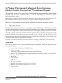
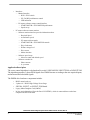
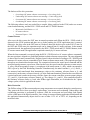
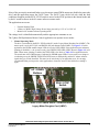
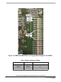
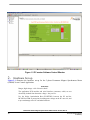
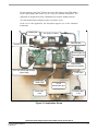
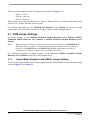
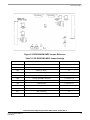
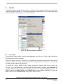
56F8300 3-Phase Permanent Magnet Synchronous
Motor Vector Control using Processor Expert
Targeting Document
MC56F8300
16-bit Digital Signal Controllers
8300PMSMTD
Rev. 0
1/2005
freescale.com
Document Revision History
Version History
Rev 0
Description of Change
Initial public release
3 Phase Permanent Magnet Synchronous Motor Vector Control, Rev. 0
2
Freescale Semiconductor
Preliminary
3-Phase Permanent Magnet Synchronous
Motor Vector Control on Processor Expert
This application exercises vector control of the 3-Phase Permanent Magnet Synchronous Motor (PMSM)
using Processor Expert (PE), a 56F8346, 56F8357, or 56F8367 EVM board and a 3-Phase AC / BLDC
High-Voltage Power Stage.
Applications developed for this demonstration board were not designed for the 56F8100 devices. The
56F8300 demonstration board does, however, fully support 56F8100 software development.
Note: The PC master software referenced in this document is also known as Free Master software.
1.
Specifications
This application performs principal vector control of the 3-phase PMSM using a 56F8300 processor. The
concept of the application is a speed closed-loop PM synchronous drive using a vector control technique.
The control technique obtains d and q current components from regularly sampled 3-phase stator currents.
The d and q current components are then controlled separately. The q component corresponds to torque
and the d component corresponds to flux. An incremental encoder is used to derive the actual rotor speed.
The Actual Speed, derived from a quadrature decoder, monitors the actual behavior of the system, and is
compared with the reference signal (Required Speed).
Protection is provided against drive faults Overcurrent, Overvoltage, Undervoltage, and Overheating.
System Outline
The system is designed to drive a 3-phase permanent magnet synchronous motor. The application has the
following specifications:
•
•
•
•
•
•
•
•
•
•
•
Vector control technique used for PMSM control
Speed control loop
Targeted for a 56F8346EVM, 56F8357EVM, or 56F8367EVM
Runs on a 3-phase PMSM control development platform at a variable line voltage, 115V AC and 230V
AC (range of -15% to +10%)
Motor mode
Generator mode
DCBus brake
Minimum speed 50rpm
Maximum speed 3000rpm at input power line 230V AC
Maximum speed 1500rpm at input power line 115V AC
Fault protection
3 Phase Permanent Magnet Synchronous Motor Vector Control, Rev. 0
Freescale Semiconductor
Preliminary
3
•
Interfaces:
— Manual interface
— RUN / STOP switch
— UP / DOWN push buttons control
— LED indication
— PC master software remote control interface
— START MOTOR / STOP MOTOR push buttons
— Speed set-up
•
PC master software remote monitor
— Software monitor interface provides information about:
— Required Speed
— Actual motor speed
— PC master software mode
— START MOTOR / STOP MOTOR controls
— Drive fault status
— DCBus voltage level
— Drive status
— Mains detection
— Software speed scope
— Observes actual and desired speed
— Software recorder for:
— Phase currents
— d, q currents
Application Description
The vector control algorithm is calculated on Freescale’s 56F8346EVM, 56F8357EVM, or 56F8367EVM.
The algorithm generates 3-phase PWM signals for a PMSM inverter according to the user-required inputs,
and measured and calculated signals.
The PMSM drive hardware components include:
•
•
•
•
•
BLDC motor-brake set
3-phase AC / BLDC High-Voltage Power Stage
56F8346, 56F8357, or 56F8367 EVM board
Legacy Motor Daughter Card (LMDC)
In-line optoisolation box (Freescale Part # ECOPTINL), which is connected between the host
computer and the EVM board
3 Phase Permanent Magnet Synchronous Motor Vector Control, Rev. 0
4
Freescale Semiconductor
Preliminary
The BLDC motor-brake set incorporates a 3-phase BLDC motor and an attached BLDC motor brake. The
BLDC motor has six poles. The incremental position sensor (encoder) is coupled on the motor shaft and
position Hall Sensors are mounted between the motor and the brake. They allow position sensing if
required by the control algorithm. Detailed motor-brake specifications are listed in Table 1-1.
Note:
The application software is targeted for PMSM with sine-wave Back-EMF shape. In this demo
application, the BLDC motor is used instead, due to the availability of the BLDC motor-brake SM40V
+ SG40N, supplied as Freescale Part #ECMTRHIVBLDC. Although the Back-EMF shape of this
motor is not ideally sine-wave, it can be controlled by the application software. The drive parameters
will be improved when a PMSM motor with an exact sine-wave Back-EMF shape is used.
Table 1-1 Motor Brake Specifications
Motor
Drive Characteristics
Motor Characteristics
Motor Type
6 poles, 3-phase, star connected, BLDC motor
Speed Range
2500rpm (at 310V)
Maximum Electrical Power
150W
Phase Voltage
3 x 200V
Phase Current
0.55A
Speed Range
< 2500rpm
Input Voltage
310V DC
Maximum DCBus Voltage
380V DC
Control Algorithm
Speed Closed-Loop Control
Optoisolation
Required
Motor type
6 poles, 3-phase, star connected, BLDC motor
Speed Range
150W
Maximum Electrical Power
150W
The drive can be controlled in two operating modes:
•
•
In the Manual operating mode, the required speed is set by the UP / DOWN push buttons and the
drive is started and stopped by the RUN / STOP switch on the EVM board
In the PC master software operating mode, the required speed is set by the PC master software
active bar graph and the drive is started and stopped by the START MOTOR and STOP MOTOR
controls
Measured quantities:
•
•
•
•
DCBus voltage
Phase currents (Phase A, Phase B, Phase C)
Power module temperature
Rotor speed
3 Phase Permanent Magnet Synchronous Motor Vector Control, Rev. 0
Freescale Semiconductor
Preliminary
5
The faults used for drive protection:
•
•
•
•
Overvoltage (PC master software error message = Overvoltage fault)
Undervoltage (PC master software error message = Undervoltage fault)
Overcurrent (PC master software error message = Overcurrent fault)
Overheating (PC master software error message = Overheating fault)
The following software tools are needed for to compile, debug, and load to the EVM, and to use remote
control and monitoring, and the RUN / STOP switch and UP / DOWN buttons:
•
•
•
Metrowerks CodeWarrior v. 6.1.2
PC master software
Processor Expert v. 2.94
Control Process
After reset, the drive enters the INIT state in manual operation mode.When the RUN / STOP switch is
detected in the STOP position and there are no faults pending, the STOP application state is entered.
Otherwise, the drive waits in the INIT state or if faults are detected, the drive goes to the FAULT state. In
the INIT and STOP states, the operation mode can be changed from PC master software. In the manual
operational mode, the application is operated by the RUN / STOP switch and UP / DOWN buttons; in the
PC master remote mode, the application is operated remotely by PC master software.
When the Start command is accepted (using the RUN / STOP Switch or PC master software command),
the rotor position is aligned to a predefined position to obtain a known rotor position. The rotor alignment
is done at the first start command only. Required speed is then calculated according to UP / DOWN push
buttons or PC master software commands (if in PC master software remote mode). The required speed goes
through an acceleration/deceleration ramp. The comparison between the actual speed command and the
measured speed generates a speed error. Based on the error, the speed controller generates a stator current,
Is_qReq, which corresponds to torque. A second part of the stator current, Is_dReq, which corresponds to
flux, is given by the Field Weakening Controller. Simultaneously, the stator currents Is_a, Is_b and Is_c
are measured and transformed from instantaneous values to the stationary reference frame α, β, and
consecutively to the rotary reference frame d, q (Clarke-Park transformation). Based on the errors between
required and actual currents in the rotary reference frame, the current controllers generate output voltages
Us_q and Us_d (in the rotary reference frame d, q). The voltages Us_q and Us_d are transformed back to
the stationary reference frame α, β and, after DCBus ripple elimination, are recalculated to the 3-phase
voltage system, which is applied on the motor.
Drive Protection
The DCBus voltage, DCBus current and power stage temperature are measured during the control process.
They protect the drive from overvoltage, undervoltage, overcurrent and overheating. Undervoltage and
overheating protection is performed by software, while the overcurrent and overvoltage fault signals
utilize a fault input of the hybrid controller. Line voltage is measured during application initialization and
the application automatically adjusts itself to run at either 115V AC or 230V AC, depending on the
measured value.
3 Phase Permanent Magnet Synchronous Motor Vector Control, Rev. 0
6
Freescale Semiconductor
Preliminary
If any of the previously mentioned faults occur, the motor control PWM outputs are disabled to protect the
drive, and the application enters the FAULT state. The FAULT state can be left only when the fault
conditions disappear and the RUN / STOP switch is moved to the STOP position in the manual mode and
by the PC master software in the PC master software remote mode.
The application can run on:
•
•
•
External RAM or Flash
3-Phase AC/BLDC High-Voltage Power Stage powered by 115V AC or 230V AC
Manual or PC master software operating mode
The voltage level is identified automatically and the appropriate constants are set.
The 3-phase PM Synchronous Motor Control Application can operate in two modes:
1. Manual Operating Mode
The drive is controlled by the RUN / STOP switch (S3) on the Legacy Motor Daughter Card (LMDC). The
motor speed is set by the UP (S1) and DOWN (S2) push buttons on the LMDC; see Figure 1-1. In this
application, the PWMA module output LEDs are used as USER LEDS. If the application runs and motor
spinning is disabled (i.e., the system is ready), the GREEN USER LED (LED2, shown in Figure 1-2) will
blink. When motor spinning is enabled, the USER LED is On. Refer to Table 1-2 for application states.
The actual state of the PWM outputs is indicated by PWMB output LEDs. If overcurrent, overvoltage or
overheating occur, the GREEN USER LED (LED2) starts to flash quickly and the PC master software
signals the type of fault identified. This state can be exited only by an application reset. It is strongly
recommended that you inspect the entire application to locate the source of the fault before starting it
again.
UP / DOWN
Buttons
RUN / STOP
Switch
Figure 1-1 RUN / STOP Switch and UP / DOWN Buttons on the
Legacy Motor Daughter Card (LMDC)
3 Phase Permanent Magnet Synchronous Motor Vector Control, Rev. 0
Freescale Semiconductor
Preliminary
7
Figure 1-2 USER and PWM LEDS on the Legacy Motor Daughter Card (LMDC)
Table 1-2 Motor Application States
Application State
Motor State
Green LED State
Stopped
Stopped
Blinking at a frequency of 2Hz
Running
Spinning
On
Fault
Stopped
Blinking at a frequency of 8Hz
3 Phase Permanent Magnet Synchronous Motor Vector Control, Rev. 0
8
Freescale Semiconductor
Preliminary
2. PC Master Software (Remote) Operating Mode
The drive is controlled remotely from a PC through the SCI communication channel of the hybrid
controller via an RS-232 physical interface. The drive is enabled by the RUN / STOP switch, which can be
used to safely stop the application at any time. PC master software enables the user to set the motor’s
Required Speed.
The following PC master software control actions are supported:
•
•
•
•
•
Set the motor control system’s PC master software mode
Set the motor control system’s manual mode
Start the motor
Stop the motor
Set the motor’s Required Speed
PC master software displays the following information:
•
•
•
The motor’s Required Speed
The motor’s Actual Speed
Application status
— Init
— Stop
— Run
— Fault
• DCBus voltage level
• Identified line voltage
• Fault Status
— No_Fault
— Overvoltage
— Overcurrent
— Undervoltage
— Overheating
Start the PC master software window’s application, 3ph_pmsm_vector_control.pmp. Figure 1-3 illustrates
the PC master software control window after this project has been launched.
Note:
If the PC master software project (.pmp file) is unable to control the application, it is possible that the
wrong load map (.elf file) has been selected. PC master software uses the load map to determine
addresses for global variables being monitored. Once the PC master software project has been
launched, this option may be selected in the PC master software window under Project / Select Other
Map File Reload.
3 Phase Permanent Magnet Synchronous Motor Vector Control, Rev. 0
Freescale Semiconductor
Preliminary
9
Figure 1-3 PC master Software Control Window
2.
Hardware Set-up
Figure 2-1 illustrates the hardware set-up for the 3-phase Permanent Magnet Synchronous Motor
(PMSM) Vector Control Application.
WARNING:
Danger, high voltage—risk of electric shock!
The application PCB modules and serial interface (connector, cable) are not
electrically isolated from the mains voltage—they are live.
Use the In-line Optoisolation Box (ECOPTINL) between the PC and the
MC56F83xxEVM as protection from dangerous voltage on the PC-user side, and
to prevent damage to the PC and other hardware.
3 Phase Permanent Magnet Synchronous Motor Vector Control, Rev. 0
10
Freescale Semiconductor
Preliminary
Do not touch any part of the EVM or the serial cable between the EVM and the
In-line Optoisolation Box unless you are using an insulation transformer. The
application is designed to be fully controllable only from PC master software.
To avoid inadvertently touching live parts, use plastic covers.
In the rest of this application, the description supposes use of the insulation
transformer.
Power Line
Line
Power
3-ph
3-Ph.BLDC
BLDCHV
HVMotor
Motor
56F83xxEVM
MC56F8346EVM
Encoder
Encoder Connector
Connector
PowerSupply
Supplyfor
Power
for Opto Box
Optoisolation
Box
Legacy Motor
Daughter
Board
Daughter
Card
(LMDC)
(LMDC
Board)
3-Ph. AC Power
/ BLDCStage
High-Voltage
3ph AC Power
/ BLDCStage
High Voltage
JTAG Cable
JTAG
Cable
Serial
Serial Cable
In-Line
In-Line
Opto Box Box
Optoisolation
Serial Cable
Serial
to PC
to
Paralel Cable
Parallel
Cable
to PC
Figure 2-1 Application Set-up
3 Phase Permanent Magnet Synchronous Motor Vector Control, Rev. 0
Freescale Semiconductor
Preliminary
11
The correct order of phases for the AC induction motor shown in Figure 2-1 is:
•
•
•
Phase A = red wire
Phase B = white wire
Phase C = black wire
When facing a motor shaft, the phase order is: Phase A, Phase B, Phase C; the motor shaft should rotate
clockwise (i.e., positive direction, positive speed).
For detailed information, see the 56F83xxEVM Hardware User Manual for the device being
implemented. The serial cable is needed only for the PC master software debugging tool.
2.1 EVM Jumper Settings
For jumper settings, see the 56F8346 Evaluation Module Hardware User’s Manual, 56F8357
Evaluation Module Hardware User’s Manual or 56F8367 Evaluation Module Hardware User’s
Manual.
Note:
When running the EVM target system in a stand-alone mode from Flash, in the 56F8346EVM, the
JG9 jumper must be set in the 1-2 configuration to disable the command converter parallel port
interface. In the 56F8357EVM or the 56F8367EVM, the JG3 jumper must be set in the 1-2
configuration to disable the command converter parallel port interface.
For a detailed description for jumper settings, see the appropriate 56F83xx Evaluation Module
Hardware User’s Manual for the device being implemented.
2.1.1
Legacy Motor Daughter Card (LMDC) Jumper Settings
To execute the 3-phase PMSM Vector Control Application, the 56F8300 LMDC requires the strap settings
shown in Figure 2-2 and Table 2-1.
3 Phase Permanent Magnet Synchronous Motor Vector Control, Rev. 0
12
Freescale Semiconductor
Preliminary
EVM Jumper Settings
Figure 2-2 56F8300EVM LMDC Jumper Reference
Table 2-1 56F8300EVM LMDC Jumper Settings
Jumper Group
Comment
Connections
JG1
Primary PFC
1-2 & 3-4 & 5-6 & 7-8 & 9-10
JG2
Secondary PFC
NC
JG3
Phase_IS / Over_I
2-3
JG4
Primary Zero-Crossing / Encoder
2-3 & 5-6 & 8-9
JG5
Secondary Zero-Crossing / Encoder
2-3 & 5-6 & 8-9
JG6
Primary Back-EMF / Phase-IS
1-2 & 4-5 & 7-8
JG7
Secondary Back-EMF / Phase-IS
1-2 & 4-5 & 7-8
JG8
Fault A Monitor
1-2 & 3-4 & 5-6
JG9
Fault B Monitor
1-2 & 3-4 & 5-6
JG10
Switch 1 (Up)
1-2
JG11
Switch 2 (Down)
1-2
JG12
Switch 3 (Run / Stop)
1-2
3 Phase Permanent Magnet Synchronous Motor Vector Control, Rev. 0
Freescale Semiconductor
Preliminary
13
3.
Build
To build this application, open the 3ph_pmsm_vc_56F83xx_onPE.mcp project file and execute the Make
command, as shown in Figure 3-1. This will build and link the 3-phase PMSM Vector Control Application
and all needed Metrowerks and Processor Expert libraries.
Figure 3-1 Execute Make Command
4.
Execute
To execute the 3-phase PMSM Vector Control application, select Project / Debug in the CodeWarrior
IDE, followed by the Run command.
If the Flash target is selected, CodeWarrior will automatically program the internal Flash of the hybrid
controller with the executable generated during Build. If the External RAM target is selected, the
executable will be loaded to off-chip RAM.
To execute the 3-phase PMSM Vector Control Application’s internal Flash version, choose the
Program / Debug command in the CodeWarrior IDE and when loading is finished, in the 56F8346EVM,
set jumper JG9 to disable the JTAG port and JG3 to enable boot from internal Flash, then push the
RESET button. In the 56F8357EVM or the 56F8367EVM, set jumper JG3 to disable the JTAG port and
JG4 to enable boot from internal Flash, then push the RESET button.
3 Phase Permanent Magnet Synchronous Motor Vector Control, Rev. 0
14
Freescale Semiconductor
Preliminary
EVM Jumper Settings
For more help with these commands, refer to the CodeWarrior tutorial documentation in the following file,
located in the CodeWarrior installation directory:
<...>\CodeWarrior Manuals \ PDF \ Targeting_56800E.pdf
For jumper settings, see the appropriate 56F83xx Evaluation Module Hardware User’s Manual for the
device being implemented.
Once the application is running, move the RUN / STOP switch to the RUN position and set the required
speed with the UP / DOWN push buttons. Pressing the UP / DOWN buttons should incrementally increase
the motor speed until it reaches maximum speed. If successful, the 3-phase PMSM will be spinning.
Note: If the RUN / STOP switch is set to the RUN position when the application starts, toggle the
RUN / STOP switch between the STOP and RUN positions to enable motor spinning. This is a protection
feature that prevents the motor from starting when the application is executed from CodeWarrior. You
should also see a lighted green LED, which indicates that the application is running. If the application is
stopped, the green LED will blink at a 2Hz frequency. If an undervoltage, overvoltage, overcurrent, or
overheating fault occurs, the green LED will blink at a frequency of 8Hz.
3 Phase Permanent Magnet Synchronous Motor Vector Control, Rev. 0
Freescale Semiconductor
Preliminary
15
How to Reach Us:
Home Page:
www.freescale.com
E-mail:
[email protected]
USA/Europe or Locations Not Listed:
Freescale Semiconductor
Technical Information Center, CH370
1300 N. Alma School Road
Chandler, Arizona 85224
+1-800-521-6274 or +1-480-768-2130
[email protected]
Europe, Middle East, and Africa:
Freescale Halbleiter Deutschland GmbH
Technical Information Center
Schatzbogen 7
81829 Muenchen, Germany
+44 1296 380 456 (English)
+46 8 52200080 (English)
+49 89 92103 559 (German)
+33 1 69 35 48 48 (French)
[email protected]
Japan:
Freescale Semiconductor Japan Ltd.
Headquarters
ARCO Tower 15F
1-8-1, Shimo-Meguro, Meguro-ku,
Tokyo 153-0064, Japan
0120 191014 or +81 3 5437 9125
[email protected]
Asia/Pacific:
Freescale Semiconductor Hong Kong Ltd.
Technical Information Center
2 Dai King Street
Tai Po Industrial Estate
Tai Po, N.T., Hong Kong
+800 2666 8080
[email protected]
For Literature Requests Only:
Freescale Semiconductor Literature Distribution Center
P.O. Box 5405
Denver, Colorado 80217
1-800-441-2447 or 303-675-2140
Fax: 303-675-2150
[email protected]
Information in this document is provided solely to enable system and
software implementers to use Freescale Semiconductor products. There are
no express or implied copyright licenses granted hereunder to design or
fabricate any integrated circuits or integrated circuits based on the
information in this document.
Freescale Semiconductor reserves the right to make changes without further
notice to any products herein. Freescale Semiconductor makes no warranty,
representation or guarantee regarding the suitability of its products for any
particular purpose, nor does Freescale Semiconductor assume any liability
arising out of the application or use of any product or circuit, and specifically
disclaims any and all liability, including without limitation consequential or
incidental damages. “Typical” parameters that may be provided in Freescale
Semiconductor data sheets and/or specifications can and do vary in different
applications and actual performance may vary over time. All operating
parameters, including “Typicals”, must be validated for each customer
application by customer’s technical experts. Freescale Semiconductor does
not convey any license under its patent rights nor the rights of others.
Freescale Semiconductor products are not designed, intended, or authorized
for use as components in systems intended for surgical implant into the body,
or other applications intended to support or sustain life, or for any other
application in which the failure of the Freescale Semiconductor product could
create a situation where personal injury or death may occur. Should Buyer
purchase or use Freescale Semiconductor products for any such unintended
or unauthorized application, Buyer shall indemnify and hold Freescale
Semiconductor and its officers, employees, subsidiaries, affiliates, and
distributors harmless against all claims, costs, damages, and expenses, and
reasonable attorney fees arising out of, directly or indirectly, any claim of
personal injury or death associated with such unintended or unauthorized
use, even if such claim alleges that Freescale Semiconductor was negligent
regarding the design or manufacture of the part.
Freescale™ and the Freescale logo are trademarks of Freescale Semiconductor, Inc.
All other product or service names are the property of their respective owners.
This product incorporates SuperFlash® technology licensed from SST.
© Freescale Semiconductor, Inc. 2004. All rights reserved.
8300PMSMTD
Rev. 0
1/2005