1
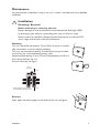
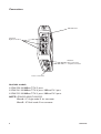
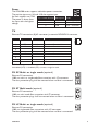
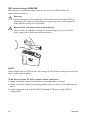
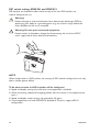
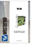
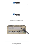
SDW-500
S E R I E S
6644-2212
Industrial Ethernet
5-port Switch
www.westermo.com
© Westermo Teleindustri AB • 2005
User Guide
Safety
!
!
General:
Before using this unit, read this manual completely and gather all information on
the unit. Make sure that you understand it fully. Check that your application does
not exceed the safe operating specifications for this unit.
Before installation, maintenance or modification work:
Prevent damage to internal electronics from electrostatic discharges (ESD)
by discharging your body to a grounding point (e.g. use of wrist strap).
Prevent access to hazardous voltages by disconnecting the unit from AC/DC
mains supply and all other electrical connections.
Installation:
!
This unit should only be installed by qualified personnel.
This unit should only be installed in a “restricted access area”, for example
a lockable cabinet where access is restricted to service personnel only.
This unit is intended for permanent connection to the AC/DC mains supply.
The power supply wiring must be sufficiently fused, and if necessary it must be
possible to disconnect manually from the AC/DC mains supply. Ensure compliance
to national installation regulations.
Units with the rated voltage exceeding 42.4 V peak or 60 VDC, are defined as
class I equipment with a protective earthing conductor terminal.
Units with the rated voltage up to 42.4 V peak or 60 VDC, are defined as class III
equipment and shall be separated from hazardous voltage by double or reinforced
isolation.
This unit uses convection cooling.To avoid obstructing the air flow around the
unit, follow the spacing recommendations (see Installation section).
Approvals
Conformity with the Directive 73/23/EEC Low Voltage Directive – LVD has been
assessed by application of the standard EN 60 950.
Conformity with the Directive 89/336/EEC Electromagnetic Compatibility (EMC)
has been assessed by application of standards EN 61000-6-2 (industrial immunity)
and EN 61000-6-3 (residential emission) and EN61000-6-4 (Industrial emission).
2
6644-2212
Description
The SDW-500 is a series of Industrial Ethernet 5-port switches.
Several variations are available ranging from a version with five RJ-45 TX (copper) ports
to versions having two FX (fibre) and three TX ports.
All TX ports support auto-negotiation, but DIP-switches also allow speed and duplex
configuration of any individual TX port. It is also possible to set up one port to monitor
traffic to/from the switch.
The SDW-500 series has been designed to meet high industrial specifications, providing
very high dependability in harsh environmental conditions.
Features:
…
…
…
…
…
…
…
…
…
…
…
Flexible mix of TX (copper) and FX (fibre) interface
TX shields individually isolated
Wide DC power range 12–48 VDC (9.6 – 57.6 VDC operating voltage)
Wide temperature range
Redundant power
Automatic MDI/MDI-X crossover
LED indicators for Power, Speed, Duplex, Link and Traffic
Port monitoring
35 mm DIN rail mounting
SC, ST and LC fibre interface
Multi (MM) and single mode (SM) fibre
Example of applications are:
… 5-port switch
… Fibre to copper converter
… Ethernet isolator, for STP network
6644-2212
3
Declaration of Conformity
Westermo Teleindustri AB
Declaration of conformity
The manufacturer
Westermo Teleindustri AB
SE-640 40 Stora Sundby, Sweden
Herewith declares that the product(s)
Type of product
Model
Art no
Installation manual
DIN-rail
DIN-rail
DIN-rail
DIN-rail
DIN-rail
DIN-rail
DIN-rail
DIN-rail
DIN-rail
DIN-rail
DIN-rail
DIN-rail
DIN-rail
DIN-rail
SDW-550
SDW-532-MM-SC2-SM-SC15
SDW-541-MM-SC2
SDW-541-MM-ST2
SDW-541-SM-LC15
SDW-541-MM-LC2
SDW-541-SM-SC15
SDW-541-SM-LC40
SDW-532-2MM-SC2
SDW-532-2MM-ST2
SDW-532-2SM-LC15
SDW-532-2MM-LC2
SDW-532-2SM-SC15
SDW-532-2SM-LC40
3644-0010
3644-0019
3644-0020
3644-0021
3644-0022
3644-0023
3644-0024
3644-0025
3644-0030
3644-0031
3644-0032
3644-0033
3644-0034
3644-0035
6644-2212
6644-2212
6644-2212
6644-2212
6644-2212
6644-2212
6644-2212
6644-2212
6644-2212
6644-2212
6644-2212
6644-2212
6644-2212
6644-2212
is in conformity with the following EC directive(s).
No
Short name
89/336/EEG
Electromagnetic Compatibility (EMC)
References of standards applied for this EC declaration of conformity.
No
Title
Issue
EN 61000-6-2
EN 61000-6-3
Immunity for industrial environments
Emission standard for residential, commercial and
light-industrial environments (3644-0010)
Emission standard for industrial environments (36440020 and 3644-0030)
2 (2001)
1 (2001)
EN 61000-6-4
The last two digits of the year in which the CE marking was affixed:
1 (2001)
04
Hans Levin
Technical Manager
15th December2004
4
Postadress/Postal address
Tel.
Telefax
Postgiro
Bankgiro
Org.nr/
Corp. identity number
Registered office
S-640 40 Stora Sundby
016-428000
016-428001
52 72 79-4
5671-5550
556361-2604
Eskilstuna
Sweden
Int+46 16428000
Int+46 16428001
6644-2212
Specification
Power interface
Rated voltage
Operating voltage
Rated current
Rated frequency
Connection
Connector size
SDW-500 series
12–48 VDC, polarity protected
9.6 – 57.6 VDC
@12 VDC power input
SDW-550
SDW-541-MM-SC2
SDW-541-SM-LC15
SDW-541-SM-SC15
SDW-541-SM-LC40
SDW-541-MM-LC2
SDW-532-2-MM-SC2
SDW-532-2-MM-ST2
SDW-532-2-SM-LC15
SDW-532-2-SM-SC15
SDW-532-2-SM-LC40
SDW-532-2-MM-LC2
SDW-532-MM-SC2-SM-SC15
DC
Detachable screw terminal
0.2 – 2.5 mm2 (AWG 24-12)
320mA
450mA
450mA
350mA
350mA
350mA
600mA
600mA
450mA
450mA
450mA
450mA
450mA
Ethernet TX Interface
Electrical specification
Data rate
Duplex
Connection
Circuit type
Transmission range
IEEE std 802.3. 2000 edition
10 Mbit/s or 100 Mbit/s, manual or auto
Full or half, manual or auto
RJ-45, shielded
TNV-1
100 m
Ethernet FX Interface
Fibre optic specification
Data rate
Duplex
Connection
Transmission range
Position
Rx
Tx
IEEE std 802.3. 2000 edition, multi or single mode, 1300 nm
100 Mbit/s
Full
SC, ST, or LC
2, 15 or 40 km
Direction*
In
Out
Description
Receive port
Transmit port
Product marking
Rx
Tx
* Direction relative this unit
Mechanical
Dimension (W x H x D)
Weight
Mounting
Degree of protection
6644-2212
35 x 121 x 119 mm
0.2 kg
DIN-rail
IP21
5
Isolation between interfaces
Power Interface to all other
TX signal Interface to all other
TX shield Interface to all other
2.8 kV DC 2.0 kV RMS @ 50 Hz and 60 s duration
2.1 kV DC 1.5 kV RMS @ 50 Hz and 60 s duration
1.5 kV DC 1.0 kV RMS @ 50 Hz and 60 s duration
Environmental
Temperature, operating
–25 to +70°C (SDW-550),
–25 to +65°C (SDW-541),
–25 to +60°C (SDW-532)
Temperature,
storage and transportation
Relative humidity, operating
Relative humidity,
storage and transportation
–25 to +70°C
5 to 95% (non-condensing)
5 to 95% (condensation allowed outside packaging)
Configuration
Auto configured (auto-negotiation) or manually setting of speed and duplex of individual TX port,
by DIP-switches.
Port mirror function is possible to set with DIP-switch. With the port mirror function active the
switch will copy all outgoing traffic to port 1. This can be used to monitor all traffic going out
from the switch. Packets may be discarded if the total throughput exceeds the port speed of port 1.
Fibre optic power budget
Model
Transmitted wavelength
Min. output power, transmitter
Max. output power, transmitter
Input sensitivity, receiver
Min. power budget
Max. power budget
Recommended fibre cable
and core / cladding diameter
Fibre type
50/125
62.5/125
9/125
10/125
Multimode
MM-xx2
Singlemode
SM-SC15
Singlemode
SM-LC15
Singlemode
SM-LC40
1310 nm
-19 dBm
-12 dBm
-31 dBm
12 dBm
19 dBm
50/125
62.5/125
1310 nm
-15 dBm
-8 dBm
-34 dBm
19 dBm
26 dBm
9/125
10/125
1310 nm
-15 dBm
-8 dBm
-31 dBm
16 dBm
23dBm
9/125
10/125
1310 nm
-5 dBm
0 dBm
-34 dBm
29 dBm
34 dBm
9/125
10/125
Normal attenuation
@ 1310 nm multimode
Normal attenuation
@ 1310 nm singlemode
3.0 dBm/km
3.5 dBm/km
–
–
–
–
0.5 dBm/km
0.5 dBm/km
Attenuation in connectors / splices
Type
Connector
Fusion splice
Mechanical splice
6
Normal attenuation
0.2 - 0.4 dBm
0.1 dBm
0.2 dBm
6644-2212
Maintenance
No maintenance is required, as long as the unit is used as intended within the specified
conditions.
!
Installation
Mounting / Removal
Before mounting or removing the unit:
Prevent damage to internal electronics from electrostatic discharges (ESD)
by discharging your body to a grounding point (e.g. use of wrist strap).
Prevent access to hazardous voltages by disconnecting the unit from AC/DC
mains supply and all other electrical connections.
Mounting
This unit should be mounted on 35 mm DIN-rail which is horizontally mounted on a wall or cabinet backplate.
This unit uses convection cooling.To avoid obstructing the airflow
around the unit, use the following spacing rules.
Recommended spacing 25 mm (1.0 inch) above/below and 10 mm
(0.4 inches) left/right the unit.
Snap on mounting, see figure
CLICK!
10 mm *
(0.4 inches)
25 mm
* Spacing (left/right) recommended
for full operating temperature range
25 mm
Removal
Press down the black support at the back of the unit, see figure.
6644-2212
7
Connections
LED indicators
Network
RJ-45 connection
Network
Fibre connection
or RJ-45 connection
Power connection
Available models:
… SDW-550 10/100Base-T/TX: 5 ports
… SDW-541 10/100Base-T/TX: 4 ports 100Base-FX: 1 port
… SDW-532 10/100Base-T/TX: 3 ports 100Base-FX: 2 ports
NOTE! SDW-532-MM-SC2-SM-SC15
Port 4: SC Single mode 15 km connector
Port 5: SC Multi mode 2 km connector
8
6644-2212
3
Power
1
2
The SDW-500 series supports redundant power connection.
The positive input are +VA and +VB, the negative input
for both supplies are COM. 3-pos screw terminal Description Power
The power is drawn from
1
COM
0V
the input with the highest
2
+VA
A: 9.6 – 57.6 VDC
voltage.
3
+VB
B: 9.6 – 57.6 VDC
TX
Ethernet TX connection (RJ-45 connector), automatic MDI/MDI-X crossover.
Contact
1
2
3
4
5
6
7
8
Shield
Signal Name
TD+
TD–
RD+
Direction
In/Out
In/Out
In/Out
Description/Remark
Transmitted/Received data
Transmitted/Received data
Transmitted/Received data
RD–
In/Out
Transmitted/Received data
8
7
6
5
4
3
2
1
HF-connected
CAT 5 cable is recommended.
Unshielded (UTP) or shielded (STP) connector might be used.
FX SC Multi- or single mode (optional)
Ethernet FX connection.
1300 nm multi- or singlemode fibre tranceiver with SC-connector.
The dust protection plug shall be mounted when no fibre is connected.
FX ST Multi mode (optional)
Ethernet FX connection.
1300 nm multi mode fibre tranceiver with ST-connector.
The dust protection plugs shall be mounted when no fibre is connected.
FX LC Multi- or single mode (optional)
Ethernet FX connection.
1300 nm singlemode fibre transceiver with LC-connector.
The dust protection plug shall be mounted when no fibre is connected.
6644-2212
9
DIP switch settings SDW-550
DIP-switches are accessible under the lid on top of the unit. DIP-switches are
used to configure the unit.
!
Warning!
Prevent damage to internal electronics from electrostatic discharges (ESD) by
discharging your body to a grounding point (e.g. use of wrist strap), before the
lid on top/front of the unit is removed.
!
Warning! Do not open connected equipment.
Prevent access to hazardous voltages by disconnecting the unit from AC/DC
mains supply and all other electrical connections.
NOTE
When configuration via DIP-switches, the settings of DIP-switches configure the unit only
after a reboot (power off/on).
To be observe when the DIP-switches will be configured
… Speed and duplex setting only valid when auto-negotiation is disabled.
… When monitoring selected all outgoing packets from the switch is also copied to the
port 1.
… If auto-negotiation and auto MDI/MDI-X disabled all TX ports support MDI-X
configuration.
10
6644-2212
S1
S2
Port 1 settings
ON
S1
1 2 3 4 5 6 7 8
ON
S1
1 2 3 4 5 6 7 8
Auto-negotiation and
auto MDI/MDI-X disabled
Auto-negotiation and
auto MDI/MDI-X enabled
Port 4 settings
ON
S1
10 Mbit/s speed selected
ON
S2
1 2 3 4 5 6 7 8
1 2 3 4 5 6 7 8
ON
S1
100 Mbit/s speed selected
ON
S2
1 2 3 4 5 6 7 8
1 2 3 4 5 6 7 8
ON
S1
Half duplex selected
Auto-negotiation and
auto MDI/MDI-X enabled
ON
S2
1 2 3 4 5 6 7 8
Auto-negotiation and
auto MDI/MDI-X disabled
10 Mbit/s speed selected
1 2 3 4 5 6 7 8
ON
S1
Full duplex selected
ON
S2
1 2 3 4 5 6 7 8
100 Mbit/s speed selected
1 2 3 4 5 6 7 8
Port 2 settings
ON
S2
Half duplex selected
1 2 3 4 5 6 7 8
ON
S1
1 2 3 4 5 6 7 8
ON
S1
1 2 3 4 5 6 7 8
Auto-negotiation and
auto MDI/MDI-X disabled
ON
S2
Full duplex selected
1 2 3 4 5 6 7 8
Auto-negotiation and
auto MDI/MDI-X enabled
Port 5 settings
ON
S1
10 Mbit/s speed selected
1 2 3 4 5 6 7 8
ON
S2
1 2 3 4 5 6 7 8
Auto-negotiation and
auto MDI/MDI-X disabled
ON
S1
100 Mbit/s speed selected
1 2 3 4 5 6 7 8
ON
S2
1 2 3 4 5 6 7 8
Auto-negotiation and
auto MDI/MDI-X enabled
ON
S1
Half duplex selected
1 2 3 4 5 6 7 8
ON
S2
10 Mbit/s speed selected
1 2 3 4 5 6 7 8
ON
S1
Full duplex selected
1 2 3 4 5 6 7 8
ON
S2
100 Mbit/s speed selected
1 2 3 4 5 6 7 8
ON
Port 3 settings
ON
S1
1 2 3 4 5 6 7 8
ON
S1
1 2 3 4 5 6 7 8
Auto-negotiation and
auto MDI/MDI-X disabled
S2
ON
S2
Auto-negotiation and
auto MDI/MDI-X enabled
Port mirroring settings
ON
10 Mbit/s speed selected
S2
No monitoring selected
1 2 3 4 5 6 7 8
1 2 3 4 5 6 7 8
ON
ON
S1
Full duplex selected
1 2 3 4 5 6 7 8
ON
S1
Half duplex selected
1 2 3 4 5 6 7 8
100 Mbit/s speed selected
S2
Monitoring selected
1 2 3 4 5 6 7 8
1 2 3 4 5 6 7 8
ON
S2
Half duplex selected
Factory settings
1 2 3 4 5 6 7 8
ON
S2
ON
Full duplex selected
1 2 3 4 5 6 7 8
6644-2212
S1
ON
S2
1 2 3 4 5 6 7 8
1 2 3 4 5 6 7 8
11
DIP switch settings SDW-541 and SDW-532
DIP-switches are accessible under the lid on top of the unit. DIP-switches are
used to configure the unit.
!
Warning!
Prevent damage to internal electronics from electrostatic discharges (ESD) by
discharging your body to a grounding point (e.g. use of wrist strap), before the
lid on top/front of the unit is removed.
!
Warning! Do not open connected equipment.
Prevent access to hazardous voltages by disconnecting the unit from AC/DC
mains supply and all other electrical connections.
NOTE
When configuration via DIP-switches, the settings of DIP-switches configure the unit only
after a reboot (power off/on).
To be observe when the DIP-switches will be configured
… Speed and duplex setting only valid when auto-negotiation is disabled.
… When monitoring selected all outgoing packets from the switch is also copied to the
port 1.
… Speed and duplex switch settings are ignored for FX ports.
… If auto-negotiation and auto MDI/MDI-X disabled all TX ports support MDI-X
configuration.
12
6644-2212
Port 1 settings
S1
S2
ON
S1
1 2 3 4 5 6 7 8
ON
S1
1 2 3 4 5 6 7 8
Auto-negotiation and
auto MDI/MDI-X disabled
Auto-negotiation and
auto MDI/MDI-X enabled
ON
S1
10 Mbit/s speed selected
1 2 3 4 5 6 7 8
ON
S1
100 Mbit/s speed selected
Port 4 settings*
1 2 3 4 5 6 7 8
ON
S1
Half duplex selected
1 2 3 4 5 6 7 8
ON
S2
1 2 3 4 5
Auto-negotiation and auto
MDI/MDI-X disabled
ON
S1
Full duplex selected
1 2 3 4 5 6 7 8
ON
S2
1 2 3 4 5
Auto-negotiation and auto
MDI/MDI-X enabled
ON
Port 2 settings
ON
S1
1 2 3 4 5 6 7 8
ON
S1
1 2 3 4 5 6 7 8
S2
10 Mbit/s speed selected
1 2 3 4 5
ON
Auto-negotiation and
auto MDI/MDI-X disabled
S2
Auto-negotiation and
auto MDI/MDI-X enabled
S2
10 Mbit/s speed selected
S2
100 Mbit/s speed selected
1 2 3 4 5
ON
Half duplex selected
1 2 3 4 5
ON
ON
S1
1 2 3 4 5 6 7 8
Full duplex selected
1 2 3 4 5
ON
S1
100 Mbit/s speed selected
1 2 3 4 5 6 7 8
ON
S1
* Setting of port 4 is only possible when using
SDW-541.
These settings are ignored when using SDW-532
Half duplex selected
1 2 3 4 5 6 7 8
Port mirroring settings
ON
S1
Full duplex selected
ON
1 2 3 4 5 6 7 8
S2
No monitoring selected
1 2 3 4 5
Port 3 settings
ON
S1
1 2 3 4 5 6 7 8
ON
S1
1 2 3 4 5 6 7 8
Monitoring selected
1 2 3 4 5
Auto-negotiation and
auto MDI/MDI-X disabled
Auto-negotiation and
auto MDI/MDI-X enabled
Factory settings
ON
ON
S1
S2
1 2 3 4 5 6 7 8
ON
S1
ON
S2
1 2 3 4 5
10 Mbit/s speed selected
1 2 3 4 5 6 7 8
ON
S1
100 Mbit/s speed selected
1 2 3 4 5 6 7 8
ON
S2
Half duplex selected
1 2 3 4 5 6 7 8
ON
S2
Full duplex selected
1 2 3 4 5 6 7 8
6644-2212
13
LED indicators
At power on the PWR flashes during initialising.
Indicators (LED)
Power (PWR)
Link (LINK) of every port
Speed (SPD) and duplex (DPX) of TX ports
LED
PWR
Status
ON
Slow flash
Fast flash
LINK
OFF
ON
Flash
SPD
OFF
(TX only) ON
DPX
OFF
(TX only) ON
14
Indication of
Internal power, initialising OK
Initialisation progressing
Initialisation error
No Ethernet link
Good Ethernet link
Ethernet data is transmitted or received, traffic indication
10 Mbit/s
100 Mbit/s
Half duplex
Full duplex
6644-2212
Subsidiaries
Westermo OnTime AS
Gladsvei 20 0489 Oslo, Norway
Phone +47 220 903 03 • Fax +47 220 903 10
E-mail: [email protected]
Westermo Data Communications GmbH
Goethestraße 67, 68753 Waghäusel
Tel.: +49(0)7254-95400-0 • Fax.:+49(0)7254-95400-9
E-Mail: [email protected]
Westermo Data Communications Ltd
Talisman Business Centre • Duncan Road
Park Gate, Southampton • SO31 7GA
Phone: +44(0)1489 580 585 • Fax.:+44(0)1489 580586
E-Mail: [email protected]
Westermo Data Communications S.A.R.L.
9 Chemin de Chilly 91160 CHAMPLAN
Tél : +33 1 69 10 21 00 • Fax : +33 1 69 10 21 01
E-mail : [email protected]
Westermo Teleindustri AB have distributors in several countries, contact us for further information.
REV.B • 6644-2212
Westermo Teleindustri AB • SE-640 40 Stora Sundby, Sweden
Phone +46 16 42 80 00 Fax +46 16 42 80 01
E-mail: [email protected]
Westermo Web site: www.westermo.com
05.09 Mälartryck AB, Eskilstuna, Sweden
Application example