1
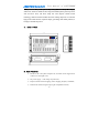
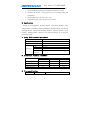
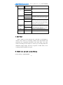
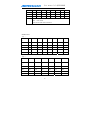
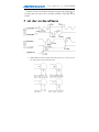
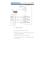
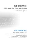
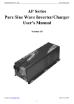
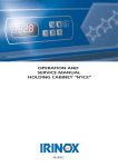
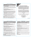
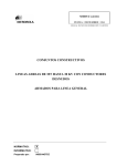
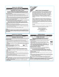
Q2BYG808M
Stepper Driver
User Manual
Adtech (Shenzhen) Technology Co., LTD
Address: F5,Tianxia IC Industrial Park, Yiyuan Rd, Nanshan
District, Shenzhen city, China P.C: 518052
TEL: +86-755-260 99116
FAX: +86-755-2672 2718
Website://www.machine-controller.com
User manual of Q2BYG808M
Copyright Warning
The property right in work regarding all the contents of this manual
is owned by Adtech (Shenzhen) Technology Co., LTD (hereinafter
referred to as Adtech), without the permission of Adtech, any company
or individual is not allowed to imitate, copy, reproduce or translate this
manual. Our company makes no warranty, express representation or
other imply regarding the contents of this manual. Adtech and its
employees assume no responsibility for any direct or indirect
information disclosure, benefit loss or business termination due to this
manual or the products information described in it. In addition, the
products and their information described in this manual are only for the
purpose of reference, we reserve the right to amend the manual without
prior notice.
All Rights Reserved, Reprint Not Allowed .
Adtech (Shenzhen) Technology Co., LTD
-1-
User manual of Q2BYG808M
Q2BYG808M 2-phase step driver equal angle, constant torque and highly
subdivision, which are suitable for drive large and middle hybrid 2-phase step motor
with 4,6 and 8 wires; The driver adopt new series bipolar constant current
technology, subdivision function makes the motor running improved, low vibration
high precision and decrease. Exquisite shapes, good design and stability features, it
belongs to desirable step driver.
1.Install Size
144.00
Mic Step Set:
2
4
Step/r
400
800
1600 3200
SW1
SW2
SW3
SW4
ON
ON
ON
ON
ON
OFF
ON
ON
ON
ON
OFF
ON
88.50
Micro-step
8
16
ON
OFF
OFF
ON
32
64
128
ON
ON
ON
OFF
ON
OFF
ON
OFF
ON
ON
OFF
OFF
Half current when sleep
Half
Full
SW5
ON
OFF
256
5
6400 12800 25600 51200 1000
ON
OFF
OFF
OFF
OFF
ON
ON
ON
10
25
50
125
250
2000 5000 10000 25000 50000
OFF
OFF
ON
ON
OFF
ON
OFF
ON
OFF
OFF
OFF
ON
OFF
ON
ON
OFF
OFF
OFF
ON
OFF
Caution:
1.Step/r=MS*200
2.Don't set current when power on
SW6
SW7
SW8
2.8A
ON
ON
ON
SW
Current Set:
3.5A
OFF
ON
ON
4.2A
ON
OFF
ON
4.9A
OFF
OFF
ON
5.7A
ON
ON
OFF
6.4A
OFF
ON
OFF
7.0A
ON
OFF
OFF
7.7A
OFF
OFF
OFF
6.50
12.00
WORK
FAULT
DR+
DRPU+
PUEN+
EN-
V+
VA+
AB+
B-
Q2BYG808M
46.50
135.00
R2
.5
0
2.Main Features
☆
Be able to drive two-phase composite 56, 85 and 86 series stepper motor
with four, six and eight wires;
☆
DC power supply,with voltage scope 40v-80v;
☆
Bipolar constant current chopping, with a chapping frequency of 20KHz;
☆
Photoelectric Isolation signal input, signal compatible with TTL;
-2-
User manual of Q2BYG808M
☆
Auto current reduction in static state, maximum drive current 8A/phase;
☆
Optional subdivision precisions with maximum subdivision of 256.
☆
Parameter shows shell,,dial up switch set for conveniently testing and
maintenance;
☆
Outline dimension L 144×88.5×46.5(㎜)
☆
Single/double pulse control mode for user selection.
3.Application
Sealing & cutting machine、Shearing machine、Pipe cutting machine、Glass
cutting machine、pack cutting machine、packaging & printing machine、CNC milling
& drilling machine、drilling & brush making machine、Engraving machine、spring
machine、Winding machine、Mortiser、blow-and blow machine etc. for precision
positioning system。
4.Using Environment & parameters
Cool Mode
Nature wind cooling
Saving Temperature
-20℃~70℃
Weight
367 克
Temperature
Environment
-5℃~50℃
Humility
35%~90%
Vibration
5.9m/s2
Work
To be Avoid oil mist, metallic dust and corrosive gas
Max
environment
5.Electronic Features(Tj=25℃)
Q2BYG808M
Project Specification
Max Value
Max Value
Unit
Work Voltage(DC)
40
80
V(DC)
Output current (phase)
2.8
7.7
A
Step Pulse frequency
0
300
KHZ
Insulation Resistance
500
∞
MΩ
6.Pin specification
Name
Mark
Function details
-3-
User manual of Q2BYG808M
Working
-
Power
+
Port of connect
A+
Motor
A-
DC(40V~80V )
B+
DC power supply
Step motor A Phase
Step Motor B phase
BEnable signal
EN+
EN-
Pulse Signal
PU-
Enable signal : The signal used for
Enable/disable. Enable upon high lover enable,
the driver can not work in low level; suspend if
not used.
Pulse signal:it is pulse control signal in single
PU+
pulse control mode and forward stepping pulse
signal in double- pulse control mode, the input
Direction
signal
DR+
DR-
Fault
indication
FAULT
signal pulse is in edge valid mode.
Direction signal:It is high/low level signal in
single pulse control mode and reverse pulse
signal in double-pulse control mode. The input
signal pulse is in edge valid mode.
Power on is normal, indication light off
Work
POWER
Power on working normal,Indication is on
indication
7.Work Power
Work voltage of power between DC (40V-80V) is belonging to
normal work, which are including related mark specification and
parameters for compatible transformer and current plate. User must
connect according to the request, as well as you can adopt other DC
stabilized voltage supply. The wave of power is under 50mc, to be
avoiding unstable supply power grid.
8.Subdivision and work current Setting
Current setting:Q2BYG808M
-4-
User manual of Q2BYG808M
Current
2.8A
3.5A
4.2A
4.9A
5.7A
6.4A
7.0A
7.7A
SW6
ON
OFF
ON
OFF
ON
OFF
ON
OFF
SW7
ON
ON
OFF
OFF
ON
ON
OFF
OFF
SW8
ON
ON
ON
ON
OFF
OFF
OFF
OFF
SW5
ON : Half current
OFF: Full current
Semi-current state when motionless
Subdivision:
Type 一:
Subdivision
2
4
8
16
32
64
128
256
Step/rotation
400
800
1600
3200
6400
12800
25600
51200
SW1
ON
ON
ON
ON
ON
ON
ON
ON
SW2
ON
OFF
ON
OFF
ON
OFF
ON
OFF
SW3
ON
ON
OFF
OFF
ON
ON
OFF
OFF
SW4
ON
ON
ON
ON
OFF
OFF
OFF
OFF
No.
Type 二:
5
10
25
50
125
250
1000
2000
5000
10000
25000
50000
SW1
OFF
OFF
OFF
OFF
OFF
OFF
SW2
ON
OFF
ON
OFF
ON
OFF
SW3
ON
ON
OFF
OFF
ON
ON
SW4
ON
ON
ON
ON
OFF
OFF
Subdivision
No.
Step/Rotati
on
-5-
User manual of Q2BYG808M
Specification:
The Driver Provides two control modes: double pulse (P+P)and single pulse(P+D),User
can setting on/off in the plate of driver conveniently according to output signal mode of
controller.
9.Input signal wave shape and Sequence
☆
Q2BYG808M can drive 2-phase hybrid step motor of 4, 6 and 8 wires for
all current under 6A/8A, details as below:
-6-
User manual of Q2BYG808M
☆
Motor Selection & Driver Features:
A. According to the speed request of system make choose for selecting
step motor or servo motor. The step motor frequency torque will as the
motor speed increase, and output torque will decrease. In generally for
light load, the maximum working speed about 15 rotations per second;
under the heavy load, the maximum working speed is 15 rotations per
second. If the system has higher speed request, you can used servo
motor.
per second
B After confirmed the model of step motor, select available torque based
on the load big or small.
C In the running, you can change the gear ratio according the gearbox,
and it can adjust the relationship for torque and load.
D Increase the power supply for step drive can improving working speed
of motor; Increase the working current can improving the torque;
increase the subdivision can improving precision of motor, as well as
make the motor running stably, decrease the libration and noise
E When the Step motor working with low speed, which will resonance
with machine sometimes, User have to trip off this speed phase.
11.Wiring of driver
A whole set of control system are including controller, driver, step motor, DC
working supply as below:
-7-
User manual of Q2BYG808M
12. Matters need attention
Please read the User manual before you use the driver
Please connect wire as request, avoid power not stably and be sure not
connect against working supply
Working current setting are 1.2 time of motor rated current
If the motor working30~50 minutes,the temperature high continues,
increase the current
-8-
User manual of Q2BYG808M
In generally, 8 wires motor higher speed of parallel connection than series
connection. Torque bigger in series connection than parallel
Be not sure to adjust current or subdivision power on/off when in the
running
Driver can be install in the place of dry and ventilation for conveniently
extend the using life
Be avoid to frequency power on/off working power acute vibration
The input voltage of control parts ( like PLC controller) connect driver,
+24VDC must parallel 2K resistance, +12VDC must parallel 1K
resistance
-9-