1
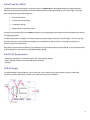
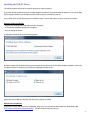
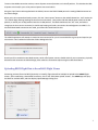
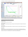
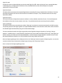
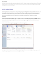
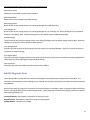
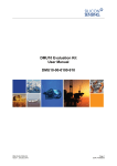
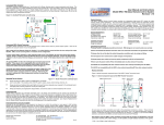
 RRC3 – Rocket Recovery Controller 3 mDACS/USB‐IO User Manual Revision 1.01 Missile Works Corporation
PO Box 1725, Lyons CO 80540
www.missileworks.com
1
mDACS and the USB‐IO The RRC3 altimeter was developed in conjunction with the mDACS (Missile Works Data Acquisition and Configuration Software) to provide the Advanced Flyer with the detailed dynamic data captured during your rocket flights. The Data items captured during your RRC3 flight are: •
20 Hz Pressure Data •
1 Hz Altimeter Temperature •
1 Hz Battery Voltage •
Drogue, Main, and Auxiliary Events Using the 20 Hz pressure RRC3 data, mDACS calculates the corresponding rocket altitude and rocket displacement velocity for graphing purposes. The RRC3 keeps the last 15 flights in its onboard memory, and thereafter writes over the oldest flight. You can fly all day and collect data, then upload and save each flight to your Windows PC after the launch. Each flight records up to a maximum of just over 28 minutes. Flight data is acquired from the RRC3 by your Windows PC using the Missile Works USB‐IO dongle, or the PerfectFlite DT2U or DT3U dongles (in conjunction with the MWPF Adapter Board) mDACS PC Requirements ∙ Windows XP, Windows 7 or Windows 8 with .NET 4.0 framework support ∙ 1024 x 768 pixel minimum recommended display resolution ∙ USB port USB‐IO Dongle The USB‐IO dongle is pictured below. You’ll notice that it has 2 status LED for communication activity, a USB cable connection, a power slide switch, and the same COM connector used on the RRC3. 2
Installing the USB‐IO Driver The USB IO module requires driver support software in order to operate. If you have already installed and run the Featherweight FIP software, PerfectFlite DataCap software, or any of the BRB tracker support software, you already have the necessary drivers installed for your PC. If not, follow either of the following driver installation steps. Your PC will require an active internet connection. Windows Update Installation ‐ Plug the USB‐IO dongle and USB cable into your computer. ‐ A “Found New Hardware” dialog box will appear. ‐ Click this dialog for details. A dialog box should similar to the following appear: Windows Update will automatically locate and install the latest drivers for the FT232R USB UART hardware. When the installation process is complete, you should see a dialog box similar to this: Make note of the COM Port Number (the above port example is COM3) Manual Driver Installation Alternatively, locate and run the file “CDM20828_Setup.exe” from the Missile Works Web Site “Download” page (http://www.missileworks.com/downloads/). This will install the necessary drivers. 3
Installing the mDACS Application Software Locate and run the latest mDACS Setup and Installation program from the Missile Works Web Site “Downloads” page (http://www.missileworks.com/downloads/). Click on the app software installation link, and either download and run the installer directly on your PC or open and run the installer on the web site. After you successfully install your mDACS application, you will have a desktop shortcut available to launch the application. Double click the shortcut to launch the mDACS app. Note: If your PC does not currently have the .NET 4.0 framework support currently installed, the installation program will download and install the necessary support. Click yes if the installer detects the absence of .NET 4.0 support. You will need to have an internet connection to perform this download and install. Running mDACS for the first time The mDACS application is designed to provide a very intuitive and user friendly interface. Navigation and initiating specific mDACS operations are all launched via a single click. Here’s what you should see when you first launch the mDACS app: The mDACS application is designed to provide a very intuitive and user friendly interface. All Navigation and initiating specific mDACS operations are all launched via a single click. 4
Along the top of the mDACS window, there are 5 Primary Tabs used for navigation, providing access to the following tabbed pages: Flight Viewer Page Flight Simulator Page Settings Manager Page Diagnostic Tools Page System Preferences Page Used to upload, display, and load/save flight data from the RRC3 Simulate a flight “virtually” to validate RRC3 performance Manage, review, and load/save settings to/from the RRC3 Check all operations of the RRC3 (inputs, outputs, baro sensor) Setup the mDACS application software to your personal preferences Each page also has a “Button Bar” along the left side of the window. The button operations are specific to each tabbed page. The “Host Connect” and “Host Disconnect” buttons are shared between several pages... these are common operations amongst them. Along the bottom of the mDACS window is the Status Bar, which displays version data and communication status info. The first thing you need to set up in the application is the “COM” port that is assigned to the USB IO dongle you’ll be using with the RRC3. This setting is located on the System Preferences Page. Be sure your USB‐IO or DT2U/DT3U dongle is connected to your PC. Click on the Active Comm Port Drop Down box arrow to display the COM ports available. If you had no drivers previously installed, use the same COM port that was assigned during your driver installation process as noted above. Otherwise, if you are already using the PerfectFlite DT2U/DT3U hardware, select the same COM port used in the DataCap software. 5
After you have selected the appropriate COM port, your status bar should look like this: mDACS System Preferences The System Preferences items are defined as follows: Active Comm Port Establishes the COM port mDACS uses to communicate with the RRC3 Altitude Units Velocity Unit Temperature Units Default Data File Folder Altitude Calculation Method These settings control what units of measure are applied in mDACS Specifies where mDACS reads/writes Settings and Flight Data (defaults to “My Documents”) Use the Standard Atmospheric Model or Geopotential derivations (refer to the “Reference” section for more info on these methods) Viewer Data Smoothing Defines the Flight Viewer Altitude/Velocity smoothing operation Settings Manager Options Controls advanced setting visibility and Settings Manager print format The System Preferences Button Bar provides the following controls: Reset App Defaults This will restore all the mDACS System Preferences back to defaults, and this will reset the mDACS Windows size and position back to original aspects and location. Check for Updates This utility will check the Missile Works web site for the availability of a newer version of the mDACS application than you are currently running. A working internet connection is required for this. Connecting mDACS to the RRC3 in Host Mode The “Host Mode” connection between mDACS and the RRC3 is the primary means of communication between the altimeter and your PC. It’s used for all operations except for the “Flight Simulator” mode. Once you have established a Host Mode connection to the RRC3, you can upload flight data, download and upload settings, or utilize any of the “Diagnostic Tools” that are available. The USB‐IO dongle can provide logic power to the RRC3 in cases where the altimeter may not have an existing power source and power switch. It can also be used passively when the RRC3 does in fact have a power source and switch (like when mounted to a complete av‐bay sled). 6
To start a Host Mode connection session, ensure all power sources/switches are in the off position. This includes the USB‐
IO power switch and/or your av‐bay external power source and switch. Using the 5‐pin/4‐wire cable supplied with the USB‐IO, connect the RRC3 COMM port to the mating COMM connector on the USB‐IO dongle. When you’re all connected and ready to start, click the “Host Connect” button on the mDACS Button Bar. You’ll notice the “TX” LED will begin flashing (sending the host connect command). Next, either slide the USB‐IO power switch to the ON position, or switch your av‐bay/external switch to its ON position. The RRC3 should emit the “Init” tone, and when it recognizes the host connect command, it should stop beeping and send a connection acknowledgement to mDACS. If a successful Host Mode connection was made, your Status Bar should look like this: The mDACS application will attempt to make the Host connection for up to 15 seconds before it gives up and requires you to intervene. Here’s what the Connection Failure Dialog looks like: Should you fail to establish a Host Mode session, switch off all power sources, double check all your connections, physically disconnect and reconnect the USB IO dongle, then restart the connection sequence again as described above. Uploading RRC3 Flight Data to the mDACS Flight Viewer Presuming you have flown the RRC3 (physically or virtually), flight data will be available to upload to the mDACS Flight Viewer. After establishing a Host Mode connection, click on the “RRC3 Data Upload” button. The mDACS app will query the RRC3 for available data, and then display Upload Manager Dialog form. 7
The Data Upload Manager attempts to pre‐select the most recent flight you’ve made, however you can select any available flight from memory. When the flight you want is selected, click the “Upload Flight” button in the dialog. The dialog will then display the message “Data Upload in Progress”, and you should also see a solid RX status LED until all the flight data has been acquired from the RRC3. When this occurs, the dialog briefly displays a message of “Data Upload Complete”, and the RX status LED will go out. The Dialog then displays a final “Generating Graph Data” message, and when the all the calculation processes are finally complete, the Data Upload Manager will close. mDACS Flight Viewer The Flight Viewer Page is where all Flight Data is presented in a graphical “Line Series” chart for detailed flight analysis and evaluation. At the upper left of the chart is the Legend. The units of measure for each item in the legend are established by the System Preferences settings. The 3 Flight Events are also depicted here (Drogue, Main, Aux) for reference. The events are always superimposed on the altitude data series The primary Y‐scale on left side of the chart is always altitude. All other chart Y‐scales are located on the right hand side of the chart. The bottom X‐scale of the chart is always displayed with a seconds “timestamp” that represent the specific data frames captured by the RRC3 during flight. Along the bottom of the Chart are 3 Control/Info panels. From left to right they are: Graph Controls This collection of controls allow you to define the specific data to display in your chart, along with the ability to replot or zoom the chart data. The zoom buttons are a fixed 120%. The visibility of data items in the chart also controls which data items are included in the Flight Data Inspection Window and the Flight Data Export file. In addition to the preset zoom buttons provided, you can select a specific region of the chart for close up inspection. Position your mouse pointer in the desired chart region, the press the SHIFT key. The mouse pointer should change to a magnifying glass. Select and highlight the region to zoom by dragging the mouse pointer. Once highlighted, release the left mouse button and the chart will zoom to the bounds of the highlighted region. Once a zoom has been activated, the chart will display horizontal and vertical slider bars, and the zooming function can also be controlled using your mouse wheel as well. Flight Summary This panel contains several pertinent data items derived from Flight Data upload or the Flight File Load from disk. It also displays the name of the currently Flight File (if applicable) . There’s also a “Note” button that provides access to “Flight Notes Editor” where you can add additional comments about this specific flight. Cursor If you click the “Show Cursor” button, the Chart will display a vertical line along the X‐axis along with the corresponding timestamp. You can use this cursor to select a specific point of interest on the chart. All the data associated with this time stamped data frame are displayed in the cursor panel. 8
The following is an example of a 2‐stage flight made with the RRC3: The Flight Viewer Button Bar provides the following controls: RRC3 Host Connect Establishes a Host Mode connection with the RRC3. RRC3 Data Upload Opens the Flight Data Upload Manager Dialog form, allowing you to upload and graph/save the flight data residing in the RRC3 memory RRC3 Data Delete Opens the Flight Data Deletion Manager Dialog form, allowing you to delete and or all previous flight data residing in the RRC3 memory. Flight File Save Allows you to save the currently displayed Flight Data to file. This can be what you just uploaded from the RRC3, or a previously saved file that you want to load and rename or annotate with comments. When clicked you’ll see a standard Windows “Save Dialog” form. All RRC3 Flight Flies use the .rff file extension (RRC3 Flight File). 9
Flight File Load Provides the means to load and display a previously saved Flight File (.rff) . When clicked you’ll see a standard Windows “Load Dialog” form. All flight data is stored in its raw, normalized format, so each file load requires a complete regeneration of all the chart data. Flight Data Export This utility allows you to export the captured Flight Data to a secondary file using a standard Excel .CSV format. The items specifically displayed in the chart are the items that are included in the export. Time, Altitude and Pressure are always exported by default. Flight Data Inspect This control will open the Flight Data Inspection window in a easily readable row/column format. The items displayed in this window are the items currently shown in the chart. Time, Altitude and Pressure are always shown by default. Flight Log Manager This utility provides access to the altimeter resident “Flight Log” record that is stored and maintained in the RRC3 memory. The primary purpose of the Flight Log data is to support additional data for users that don’t need or don’t want to examine the detailed Flight Data obtained by using a PC and the USB‐IO dongle. The items tracked and saved in the Flight Log provide previous flight data that goes beyond the “how high” did it go question. In addition there is a small collection of statistical items, that include Total Flights (32767 max), Total Flight Time (3276.7 minutes), and Total Ascent Elevation (999,999 ft). A small collection of Flight Log Data is available to users via the DIP Switch/Pushbutton interface, or it is fully accessible via the plug‐in RRC3 LCD Terminal. When the Flight Log Manager Form is displayed, click on the “Read Log” button to acquire the Flight Log data. You can also reset the statistical items contained in the Flight Log by clicking on the “Reset Stats” button. Here’s a sample of the Flight Log Manager Form: 10
Host Disconnect Terminates the active Host Mode connection session with the RRC3. The only time you should require the use of this would be if you wanted to switch between “Host” and “Sim” connection modes. If you’re done interacting with the RRC3 using mDACS, just shut down the mDACS app. mDACS Settings Manager The Settings Manager is you your portal to reading, writing, saving, and loading of all the settings available in the RRC3. All of the settings and their operations are covered extensively in the RRC3 User Manual, so they won’t be duplicated here. One can choose to display some or all of the settings by checking the associated “Show” checkbox in the System Preferences. All the controls on the Settings Manager page are “grayed out” until you load a collection of settings into mDACS. This can be accomplished by loading a settings file from your PC, or by requesting a settings “read” from an RRC3 connected to mDACS in Host Mode. Here’s a snapshot of the Settings Manager page once loaded with settings data: Note: If you set the Aux Output Controls “OCS” for an operation, you will see a corresponding flow diagram appear in the Diagram Group. Its purpose is to reinforce this OCS Logic Flow visually. 11
The Settings Manager Button Bar provides the following controls: RRC3 Host Connect Establishes a Host Mode connection with the RRC3. RRC3 Setting Read Reads all the current settings in the RRC3 memory.. RRC3 Setting Write Writes all the current settings shown in the Settings Manager to the RRC3 memory. Save Settings File Writes all the current settings shown in the Settings Manager to a PC “Settings” File. When clicked you’ll see a standard Windows “Save Dialog” form. All RRC3 Setting Files use the .rsf file extension (RRC3 Settings File). Default Settings This will override all the current settings shown in the Settings Manager with the default settings used by RRC3. Note that settings are not saved to a file or written to RRC3 memory. Print Settings Sheet Provides a printed hardcopy of all the settings currently shown in the Settings Manager. Use this as a reference sheet on the field or to validate settings. Print Legend Sheet This control will open the Legend Sheet Printer Utility. All the sheets printed here are intended to provide a supplemental reference for the setup and programming of all RRC3 settings. Host Disconnect Terminates the active Host Mode connection session with the RRC3. mDACS Diagnostic Tools These tools provides a comprehensive means of evaluating the overall performance and operation of the RRC3. The barometric and temperature sensor readings can be checked, and all inputs and outputs to the RRC3 can also be exercised and validated. Some of these tools will require the connection of an external battery to the RRC3 in order to operate and will not function if you’re running the RRC3 from the UBS‐IO dongle power. These tool groups are labeled accordingly, however the specific tools requiring a battery are: Continuity Monitor ‐ RRC3 battery required for all continuity status. Output Controls ‐ RRC3 battery required for output activation power. Voltage Monitor ‐ No battery, no voltage. 12
All the Diagnostic Tool groups with the exclusion of the “Output Controls” are “Inputs”, and thusly are all processed and displayed simultaneously when you run the Manual Monitor or the Auto Loop Monitor operations on the Diagnostic Tools page. Note that the Auto Loop Monitor runs continuously until you click the Manual Monitor button. The Batch Date query provides the means to display the date that the unit was flashed and tested for operations and can establish the service life of the RRC3. The Output Controls allow you to individually activate each output of the RRC3. IMPORTANT: ALWAYS USE EXTREME CAUTION and ensure that you have NO LIVE PYRO CHARGES attached to RRC3 when activating this Output test operation. Here’s a screenshot of the Diagnostic Tools page: mDACS Flight Simulator The Flight Simulator provides a means to fly your altimeter “virtually” on your bench and directly test and observe its operation during the course of the simulated flight. This feature is especially nice to validate the operation of the Aux Output when programmed to provide a specific OCS (Output Control Sequence). In order to run a simulated flight, the RRC3 needs to boot up and establish a “Sim Mode” connection just like a Host Mode connection. Follow the same steps as Host Mode connection, except the only difference is you’ll be using the “Sim Connect” button on the Simulator Page. 13
The Sim Connect feature is exclusive to the Flight Simulator. Along the bottom of the page are two panels: Simulation Monitor The indicators in the Simulation Monitor panel display the real‐time data altitude, velocity and time while the simulation is active and in progress. When the RRC3 has booted up completely and is finally in Launch Detect mode, the Simulation Monitor Panel will be enabled. Simulation Controls Operating the Slider Bars allows you to create an Altitude and Velocity profile that will be similar in scope to your anticipated flight regime. Click the “Plot” button at any time to see how your slider settings stack up on the graph. The “POST” checkbox allows you to enable or bypass the RRC3’s POST validation should you not wish to wait for it to complete. To run a Flight Simulation: ‐ Boot up the RRC3 and establish a “Sim Mode” connection ‐ A Dialog form will appear, advising you the RRC3 is “Initializing” (Click OK) ‐ Both TX and RX LED’s should start to blink repeatedly ‐ When the RRC3 is in Launch Detect Mode, the “Start Simulation” button and “Monitor” is enabled ‐ Click on the “Start Simulation” button to Launch 14
Once the RRC3 has “landed” in Simulation Mode, the mDACS software will automatically disconnect from the RRC3. At this point, you can reboot the RRC3 into host mode and upload the captured “Simulated” Flight Data into the Flight Viewer. The Flight Simulator Button Bar provides the following controls: RRC3 Sim Connect Establishes a Sim Mode connection with the RRC3. Start Simulation Launches the Simulation Flight when the RRC3 is ready in Launch Detect Mode Sim Disconnect Terminates the active Sim Mode connection session with the RRC3. Product Warranty Missile Works Corporation has exercised reasonable care in the design and manufacture of this product and warrants the original purchaser that the RRC3 is free of defects and that it will operate at a satisfactory level of performance for a period of one year from the original date of purchase. If the system fails to operate as specified, then return the unit (or units) within the warranty period for repair or replacement (at our discretion). The system must be returned by the original purchaser, and be free of modification or any other physical damage which renders the system inoperable. Upon repair of replacement of the unit, Missile Works Corporation will return the unit postage‐paid to the original purchaser. Product Disclaimer and Limit of Liability Because the use and application of this equipment are beyond our control, the purchaser or user agrees to hold harmless Missile Works Corporation and their agents from any and all claims, demands, actions, debts, liabilities, judgments, costs, and attorney fees arising out of, claimed on account of, or in any manner predicated upon loss or damage to property of, or injuries to or the death of any and all persons arising out of the use this equipment. Due to the nature of electronic devices, and the application and environments for those devices, the possibility of failure can never be totally ruled out. It is the responsibility of the purchaser or user of this equipment to properly test and simulate the actual conditions under which the device is intended to be used to ensure the highest degree of reliability and success. 15