1
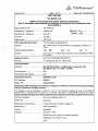
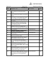
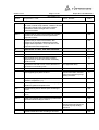
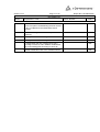
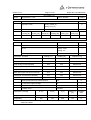
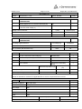
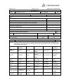
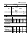
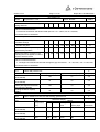
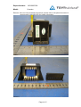
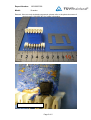
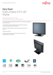
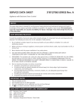
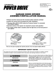
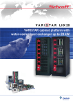
www.tuv.com
Page 2 of 18
Report No:<12012835 002>
Copy of marking plate and summary of test results (information/comments):
See appendix 1 on original report 12012835 001 for marking plates.
Summary of testing:
1. The appliance has been tested according to IEC 60335-1/IEC 60335-2-40.
2. The clauses of 7.12, 7.16, 7.101, 10, 11.8, 13, 17, 19.2, 19.14, 24.1, 29, 30 were evaluated.
3. The tests of clauses 10,11.8,13, 17,19.2, 19.14 , 30 were conducted on model K24RC with a
connection to the outdoor unit GC24RC, and the refrigerant is R22, the discharged quantity is 1660g.
4. The appliances were pre-production samples without serial numbers.
5. Please refer to the original report 12012835 001 for further information.
Test items particulars:
Serial Number................................................................: Prototype samples without serial numbers.
Additional information....................................................: N/A
Test case verdicts
Test case does not apply to the test object...................: N(.A.)
Test item does meet the requirement...........................: P(ass)
Test item does not meet the requirement.....................: F(ail)
Testing
Date of receipt of test item ...........................................: 2007.04.10
Date(s) of performance of test ......................................: 2007.04.10-2007.05.15
www.tuv.com
Page 3 of 18
Report No:<12012835 002>
General remarks
This report is not valid as a CB Test Report unless signed by an approved CB Testing Laboratory and
appended to a CB Test Certificate issued by an NCB in accordance with IECEE 02.
The test results presented in this report relate only to the item tested.
This test report shall not be reproduced except in full, without the written approval of the issuing testing
laboratory.
Clause numbers between brackets refer to clauses in IEC 60335-1
"(see Enclosure #)" refers to an additional information appended to the report.
"(see appended table)" refers to a table appended to the report.
Throughout this report a comma is used as the decimal separator.
Factory information:
Factory 1: Electra Air-Conditioning (Shenzhen) Co., Ltd.
Address:
2 Wuhe Avenue S., Bantian, Buji, Shenzhen, Guangdong, P. R. China
Factory 2:
Address:
ELECTRA CONSUMER PRODUCTS LTD.
Sapir 1, Rishon Lezion, 75704, Israel
History of amendments and modifications:
Ref.No.12012835 001, dated 2006.02.15 (original report);
Ref.No.12012835 002, dated 2007.05.24 (modification report)
Description of modification:
This report is based on 12012835 001 for alternate components for all models, please refer to the
original report for further information.
The fan motor transformer is changed from EI 54X18 to GLP-060798.
Two new pumps were used.
The fuse on the control board is changed from 3,15A to 5,0A.
Remark : see table 24.1 for details.
www.tuv.com
List of models:
Page 4 of 18
Report No:<12012835 002>
No.
Model name
Rated Voltage
Rated input
Refrigerant
1
K9RC
220-230V
42W
R22
2
K9ST
220-230V
42W
R22
3
K11RC
220-230V
42W
R22
4
K11ST
220-230V
42W
R22
5
K15RC
220-230V
54W
R22
6
K15ST
220-230V
54W
R22
7
K18RC
220-230V
66W
R22
8
K18ST
220-230V
66W
R22
9
K24RC
220-230V
78W
R22
10
K24ST
220-230V
78W
R22
11
K9RH
220-230V
1692W
R22
12
K11RH
220-230V
1692W
R22
13
K15RH
220-230V
2304W
R22
14
K18RH
220-230V
2616W
R22
15
K24RH
220-230V
2778W
R22
16
K9SH
220-230V
942W
R22
17
K11SH
220-230V
942W
R22
18
K15SH
220-230V
1554W
R22
19
K18SH
220-230V
1866W
R22
20
K24SH
220-230V
1878W
R22
21
K9RC R407C
220-230V
42W
R407C
22
K9ST R407C
220-230V
42W
R407C
23
K11RC R407C
220-230V
42W
R407C
24
K11ST R407C
220-230V
42W
R407C
25
K15RC R407C
220-230V
54W
R407C
26
K15ST R407C
220-230V
54W
R407C
27
K18RC R407C
220-230V
66W
R407C
28
K18ST R407C
220-230V
66W
R407C
29
K24RC R407C
220-230V
78W
R407C
30
K24ST R407C
220-230V
78W
R407C
31
K9RH R407C
220-230V
1692W
R407C
32
K11RH R407C
220-230V
1692W
R407C
33
K15RH R407C
220-230V
2304W
R407C
34
K18RH R407C
220-230V
2616W
R407C
www.tuv.com
List of models:
Page 5 of 18
Report No:<12012835 002>
35
K24RH R407C
220-230V
2778W
R407C
36
K9SH R407C
220-230V
942W
R407C
37
K11SH R407C
220-230V
942W
R407C
38
K15SH R407C
220-230V
1554W
R407C
39
K18SH R407C
220-230V
1866W
R407C
40
K24SH R407C
220-230V
1878W
R407C
41
K9RC R410A
220-230V
42W
R410A
42
K9ST R410A
220-230V
42W
R410A
43
K11RC R410A
220-230V
42W
R410A
44
K11ST R410A
220-230V
42W
R410A
45
K15RC R410A
220-230V
54W
R410A
46
K15ST R410A
220-230V
54W
R410A
47
K18RC R410A
220-230V
75W
R410A
48
K18ST R410A
220-230V
75W
R410A
49
K9RH R410A
220-230V
1692W
R410A
50
K11RH R410A
220-230V
1692W
R410A
51
K15RH R410A
220-230V
2304W
R410A
52
K18RH R410A
220-230V
2625W
R410A
53
K9SH R410A
220-230V
942W
R410A
54
K11SH R410A
220-230V
942W
R410A
55
K15SH R410A
220-230V
1554W
R410A
56
K18SH R410A
220-230V
1875W
R410A
Remark : see model description in original report 12012835 001 for model difference.
www.tuv.com
Page 6 of 18
Report No:<12012835 002>
IEC 60335-2-40
Clause
Requirement + Test
7
MARKING
7.12
Instructions for safe use provided
Result - Remark
P
Stated in user manual.
Classification of 6.101 included, for appliances not
accessible to general public (IEC 60335-2-40:1995)
7.12.1
Verdict
P
N/A
Sufficient details for installation or maintenance
supplied:
P
- national wiring regulations for installation (IEC
60335-2-40:1995)
Stated in user manual.
P
- dimensions of space for installation (IEC 60335-240:1995)
Stated in user manual.
P
- wiring diagram (IEC 60335-2-40:1995)
Provided.
P
- range of external static pressures (only heat pumps No static pressure required
and appliances with electric resistance heaters) (IEC
60335-2-40:1995)
N/A
- minimum clearance from appliances with
No supplementary heaters
supplementary heaters to combustible surfaces (IEC
60335-2-40:1995)
N/A
- indication of suitable parts for outdoor use (IEC
60335-2-40:1995)
N/A
Indoor unit
- method of connection to the electrical supply and
interconnection of separate components (IEC 603352-40:1995)
P
- type and rated characteristics of fuses (IEC 60335-2- 5,0A T
40:1995)
P
- details of supplementary heating elements, including
fitting instructions (IEC 60335-2-40:1995)
N/A
- maximum and minimum water or brine operating
temperatures (IEC 60335-2-40:1995)
N/A
- maximum and minimum water or brine operating
pressures (IEC 60335-2-40:1995)
N/A
- indication of open water storage tanks (IEC 60335-240:1995)
N/A
7.12.2
Means for disconnection with contact separation at
Power cord with plug
least 3 mm or instruction regarding means of
disconnection in the fixed wiring (IEC 60335-1/A2:99)
N/A
7.12.3
Insulation in contact with parts exceeding 50 K;
instruction
N/A
7.12.4
Information with regard to building-in:
Stated in the installation manual
P
- dimensions of space
P
- dimensions and position of support
P
www.tuv.com
Page 7 of 18
Report No:<12012835 002>
IEC 60335-2-40
Clause
7.12.5
Requirement + Test
Result - Remark
Verdict
- ventilation openings
P
- connection/interconnection plug accessible
P
Replacement cord, type X attachment
N/A
Replacement cord, type Y attachment
P
Replacement cord, type Z attachment
N/A
7.16
Marking of a possible replaceable thermal link or fuse Current fuse rating marked on
link clearly visible with regard to replacing the link
the PCB, near the fuse
holder:5,0A T , AC250V
P
7.101
Marking of fuses and overload protective devices, if
replaceable (IEC 60335-2-40:1995):
P
- fuse rated current in amperes, type and rated
voltage (IEC 60335-2-40:1995)
Current fuse rating marked on
the PCB, near the fuse
holder:5,0A T , AC250V
- manufacturer and model of the overload protective
device (IEC 60335-2-40:1995)
P
N/A
10
POWER INPUT AND CURRENT
P
10.1
Power input at rated voltage and normal operating
(see appended table)
temperature not deviating from rated input by more
than shown in table; measured power input (W); rated
input (W); deviation ................................................. :
P
10.2
Current at normal operating temperature not deviating Not marked on rating label
from rated current by more than shown in table;
measured current at rated voltage under normal
operation (A); rated current (A); deviation .............. :
11
HEATING
11.8
Monitored temperatures not exceeding the values of
Table 3 (IEC 60335-2-40:1995)
N/A
P
(see appended table)
P
Protective devices do not operate
P
Sealing compound not flowing out
P
Temperature of the air in the outlet duct not exceeding
90 °C (IEC 60335-2-40:1995)
N/A
13
LEAKAGE CURRENT
P
13.1
Leakage current not excessive and electric strength
adequate
P
13.2
Leakage current measured by means of circuit
described in Annex G (IEC 60335-2-40:1995)
P
13.3
Leakage current measurements
(see appended table)
P
Electric strength test of insulation. See Note in
Interpretation Sheet I-SH 02, August 1994
(see appended table)
P
No breakdown during the test
P
www.tuv.com
Page 8 of 18
Report No:<12012835 002>
IEC 60335-2-40
Clause
Requirement + Test
17
OVERLOAD PROTECTION OF TRANSFORMERS
AND ASSOCIATED CIRCUITS
P
No excessive temperatures in transformer or
associated circuits in event of short-circuits likely to
occur in normal use
P
Appliance supplied with 1,06 or 0,94 times rated
voltage and the most unfavourable short-circuit or
overload likely to occur in normal use applied
Result - Remark
(see appended table)
Verdict
P
Temperature rise of insulation of the conductors of
safety extra-low voltage circuits not exceeding the
relevant value specified in table 3 by more than 15 K
P
Temperature of the winding not exceeding the value
specified in table 6
P
Except fail-safe transformer complying 15.5 of IEC
61558-1 (IEC 60335-1/A2:1999)
Not fail-safe transformer
N/A
19
ABNORMAL OPERATION
P
19.2
Test of appliance with motor rotors, other than motor- (see appended table)
compressors, operated for 15 days (360 h) or until a
protection device opens the circuit (IEC 60335-240:1995)
P
Insulation of motor windings (IEC 60335-2-40:1995)
.................................................................................. :
(see appended table)
P
Temperature of enclosure does not exceed (°C) (IEC (see appended table)
60335-2-40:1995) ................................................... :
P
Temperature of the windings does not exceed the
values shown in the table; temperature (°C) (IEC
60335-2-40:1995) ................................................... :
P
19.14
(see appended table)
Electric strength test as specified in 16.3, 72 h after
the beginning of the test (IEC 60335-2-40:1995)
P
A 30 mA residual current device does not open (IEC
60335-2-40:1995)
P
At the end, the leakage current between the windings
and the enclosure does not exceed 2 mA (IEC 603352-40:1995)
P
No flames, molten metal, poisonous or ignitable gas
or deformed enclosures (IEC 60335-2-40:1995)
P
Temperatures rise shall not exceed the values shown The temperature rise of test
in Table 7 (IEC 60335-2-40:1995)
corner, sheath of supply cord
are lower than 175°C
P
The electric strength test, the test voltage being:
P
- basic insulation: 1000 V
P
- supplementary insulation: 2750 V
P
www.tuv.com
Page 9 of 18
Report No:<12012835 002>
IEC 60335-2-40
Clause
Requirement + Test
Result - Remark
Verdict
- reinforced insulation: 3750 V
P
24
COMPONENTS
P
24.1
Components comply with safety requirements in
relevant IEC standards
P
24.1.1
Motor-compressors not tested according to IEC
60335-2-34 (not necessary to meet all requirements
of IEC 60335-2-34) (IEC 60335-2-40:1995)
N/A
Fixed capacitors for radio interference suppression,
compliance with annex Q (IEC 60335-1/A2:1999)
P
Small lampholders: compliance with requirements for
E10 lampholders
N/A
Isolating transformers and safety isolating
transformers: compliance with IEC 61558-2-6 or
comply with annex R (IEC 60335-1/A2:1999)
N/A
Appliance couplers for IPx0 appliances: compliance
with IEC 60320
N/A
Other appliance couplers: compliance with IEC 309
N/A
Automatic controls: compliance with IEC 60730,
unless tested with the appliance
Thermal links for the
transformer and pump are
approved type.
P
Switches: compliance with IEC 61058-1, unless tested
with the appliance (IEC 60335-1/A2:1999)
N/A
24.1.2
Automatic controls complying with IEC 60730:
additional tests according to this standard and 11.3.5
to 11.3.8 and Cl. 17 of IEC 60730 as type 1 controls
(see number of cycles of operation IEC 60335-240:1995)
N/A
24.1.3
Switches tested under the conditions occurring in the
appliance, comply with annex S (IEC 603351/A2:1999)
N/A
Switch tested separately according to IEC 61058-1for
10 000 cycles of operation (IEC 60335-1/A2:1999)
N/A
Switches for no-load-operation and operable only with
the aid of a tool, are not subjected to the tests of
clauses of IEC 61058-1 This applies also to switches
operated by hand, and with interlock for no-loadoperation (IEC 60335-1/A2:1999)
N/A
Switches without this interlock subjected to the test of
Cl. 17.2.7 for 100 cycles of operation (IEC 603351/A2:1999)
N/A
24.1.4
Components marked with their operating
characteristics are used in the appliance in
accordance with these markings
P
www.tuv.com
Page 10 of 18
Report No:<12012835 002>
IEC 60335-2-40
Clause
24.1.5
Requirement + Test
Result - Remark
Verdict
Component which have to comply with other standard
is tested separately, according to the relevant
standard
P
Component used within the limits of its marking,
tested in accordance with conditions occurring in the
appliance
P
Component not marked, or not used in accordance
with its marking, or no IEC standard exists, tested
under the conditions occurring in the appliance
P
Components not mentioned in table 3 tested as part
of the appliance
P
Voltage across capacitors in series with a motor
winding does not exceed 1,1 times rated voltage,
when the appliance is supplied at 1,1 times rated
voltage under minimum load
P
Capacitors for which 30.2.3. is applicable and
permanently connected in series with a motor shall be
class P1 or P2 of IEC 60252 (IEC 60335-1/A2:1999)
P
List of components
29
CREEPAGE DISTANCES, CLEARANCES AND
DISTANCES THROUGH INSULATION
29.1
Creepage distances and clearances not less than
specified in table 13
(see appended table)
P
P
(see appended table)
Values increased by 4 mm in case of reinforced
insulation when resonance voltage
Creepage distances and clearances for circuits with
voltages greater than 250 V r.m.s. (345 V peak)
comply with table (IEC 60335-2-40:1995)
P
N/A
P
For motor-compressors with working voltages ≤
250 V, 29.1 of IEC 60335-2-34 applies (IEC 60335-240:1995)
N/A
Creepage distances and clearances for motorcompressors with working voltages > 250 V r.m.s. and
≤ 600 V r.m.s. not less than stated in Table 101 (IEC
60335-2-40:1995)
N/A
29.2
Distances through insulation not less than 1,0 mm for
supplementary insulation, and 2,0 mm for reinforced
insulation. Interpretation of this requirement: see
Interpretation Sheet I-SH 02, August, 1994
P
29.2.1
Supplementary insulation applied in thin sheet form, No such constructions.
other than mica or similar scaly material, consists of at
least two layers, each of the layers withstands the
electric strength test of 16.3 for supplementary
insulation
N/A
www.tuv.com
Page 11 of 18
Report No:<12012835 002>
IEC 60335-2-40
Clause
Requirement + Test
Result - Remark
Verdict
Reinforced insulation applied in thin sheet form, other No such constructions.
than mica or similar scaly material, consists of at least
three layers, and any two of the layers together
withstand the electric strength test of 16.3 for
reinforced insulation
N/A
Supplementary or reinforced insulation inaccessible
and does not exceed the maximum permissible
temperature values
N/A
Supplementary or reinforced insulation, after
conditioning as specified, withstands the electric
strength test as specified in 16.3, both at the oven
temperature and room temperature
N/A
30
RESISTANCE TO HEAT, FIRE AND TRACKING
P
30.1
See Annex H
P
Relevant external parts of non-metallic material
P
Parts supporting live parts and parts providing
supplementary or reinforced insulation sufficiently
resistant to heat
P
29.2.2
Ball-pressure test with a force of 20 N, diameter of
impression not exceeding 2 mm ............................. :
(see appended table)
P
External parts: at 75 °C
Transformer enclosure
P
Parts supporting live parts: at 125 °C
Transformer bobbin, terminal
support for transformer;pump
winding enclosure.
P
Parts providing supplementary or reinforced
insulation: temperature (°C)..................................... :
P
30.2
Relevant parts of non-metallic material adequately
resistant to ignition and spread of fire
P
30.2.1
Possible burning test of relevant parts according to
Annex J
N/A
Glow-wire test of Annex K made at temperature
550 °C
30.2.3
P
Appliances operated while unattended, possible badconnection test according to Annex L
Glow-wire test of Annex K made at 750 °C
Possible needle-flame test according to Annex M
N/A
Transformer bobbin, trnaformer
enclosure,terminal support for
transformer;pump winding
enclosure.
P
N/A
www.tuv.com
Page 12 of 18
Report No:<12012835 002>
IEC 60335-2-40
Clause
Requirement + Test
Result - Remark
Verdict
30.2.4
Parts of non-metallic material within a distance of
50 mm from parts not withstanding the tests of 30.2.2
or 30.2.3, subjected to the needle-flame test of
Annex M
N/A
30.3
Relevant insulating material have adequate resistance
to tracking
N/A
Tracking test at 175 V according to Annex N
N/A
Tracking test at 250 V according to Annex N
N/A
No hazard other than fire, tracking test at 175 V
according to Annex N, and in addition needle-flame
test of surrounding parts according to Annex M
N/A
Possible needle-flame test of non-metallic material
N/A
www.tuv.com
Page 13 of 18
Report No:<12012835 002>
IEC 60335-2-40
Clause
Requirement + Test
Result - Remark
Verdict
10
TABLE: input power and current
P
Operation mode: ................................
Cooling: 32/23(°C)
P
Heating: 27/-(°C)
Model
Test voltage (V): ................................
230
Rated
Rated
Measured
cooling (W) heating (W) cooling (W)
Measured
heating (W)
Deviation
cooling (%)
Deviation
heating (%)
K24RC
78
83
5,1%
6,0%
78
82
—
Limit
20%
Remark: the test was performed with all critical components and highest value was listed.
11.8
TABLE: TEMPERATURE RISE MEASUREMENTS
K24RC
t1 (°C) ...................................................................... :
25
--
t2 (°C) ...................................................................... :
Cooling: 32/23
--
P
Heating: 27/test voltage (V) ........................................................ :
temperature of part/at:
1,06x230=244V
--
Cooling (°C)
Heating (°C)
required T (°C)
Power cord
16,6
51,1
75
Pump winding enclosure(PSB-7A)
23,6
47,7
Material test
Pump winding enclosure(PSB7)
19,6
54,2
Material test
Pump wire (PSB-7A)
17,3
48,4
T105
Pump wire (PSB7)
17,3
48,4
T105
Plastic part support transformer terminal
34,2
30,2
Material test
Transformer enclosure(GLP-060798)
34,2
30,2
Material test
Test corner
32,3
26,6
90
winding temperature rise measurements:
25°C
P
K = 234,5 for copper windings ................................ : Yes
--
K = 225 for aluminium windings ............................. : --
--
insulation class ....................................................... : See below
--
temperature of winding:
R1 (Ω)
R2 (Ω)
T(°C)
required T
(°C)
insulation
class
Pump(PSB-7A)
385
451
63,6
115
E
Pump(PSB7)
399
443
53,6
115
E
Remark : The temperature rise of winding were tested in both cooling and heating modes and the highest
values were listed.
www.tuv.com
Page 14 of 18
Report No:<12012835 002>
IEC 60335-2-40
Clause
Requirement + Test
Result - Remark
13.2
TABLE: LEAKAGE CURRENT MEASUREMENTS AT OPERATING
TEMPERATURE
Verdict
P
heating appliances: at 1,15 times rated input (W) . :
N/A
--
motor-operated and combined appliances: at
1,06 times rated voltage (V) ................................... :
1,06X230=244
--
leakage current I between:
I (mA)
required I (mA)
L/N- enclosure (with aluminum foil)
0,09
0,25
L/N- earthed metal part
0,84
3,5
13.3
TABLE: ELECTRIC STRENGTH MEASUREMENTS AT OPERATING
TEMPERATURE
test voltage applied between:
P
test voltage (V)
breakdown
L/N- earthed metal part
1000
No
L/N - enclosure (with aluminum foil)
3750
No
17
TABLE: OVERLOAD PROTECTION, TEMPERATURE RISE MEASUREMENTS
P
at 1,06 or 0,94 times rated voltage (V) ................... : 1,06x230=244V
--
Ambient temperature(°C)…………………………..: 25
--
Test model…………………………………………..: GLP-060798
--
Test condition………………………………………..: Short-circuit of secondary
winding
--
Thermal couples location:
Measured temperature (°C)
Limit temperature
(°C)
Result
Primary Winding
55,4
225
P
Secondary Winding
71,2
225
P
Remark 1: 13 seconds later, the protector was operated.
Remark 2: Resistance method is not applicable due to severe complications are involved.
19.2
TABLE: LOCK MOTOR TEST, TEMPERATURE RISE MEASUREMENTS
P
Abnormal conditions:
Lock motor rotor
-
Duration:
15 days
-
Test voltage:
230V
-
T1(°C)
25
-
T2(°C)
25
-
Model
PSB7
-
Temperature of part/at (°C)
Temperature(°C)
Required temperature(°C)
Enclosure temperature
99
150
www.tuv.com
Page 15 of 18
Report No:<12012835 002>
IEC 60335-2-40
Clause
Requirement + Test
Result - Remark
Winding temperature
128
Verdict
165(impedance protected)
Result:
Protective device operated?
No
If yes ,what was the protective device?
--
How long was the operation until protective device operated?
--
Deformation of enclosure, which affect the compliance of cl.8?
No
Poisonous or ignitable gas?
No
Emit flames?
No
Molten metal?
No
LEAKAGE CURRENT MEASUREMENT
P
at 2 times rated voltage (V) .....................................:
leakage current I between:
L/N – enclosure
24.1
2x230=460V
--
I (mA)
required I (mA)
0,04
2,0
TABLE: COMPONENTS
P
Remark :For thermal links of pump which have been approved according to relevant IEC standards, the
manufacturer, types and characters not listed in the CDF but should be in this scope authorized by
original certification bodies
object/part No.
manufacturer/
trademark
type/model
Pump
for K series
Sanhua
PSB-7A
Alternate
Zhongbao
PSB7
Thermal link for
PSB-7A
Desheng
BR
Alternate
Changhong
Tongli
KW-A1
Thermal link for
PSB7
Aupo
P7
Connector for
PSB7
JST
VHR-3N
Winding of PSB7
Chengdu SouthQZY/180
west Electric
180°C
--
Winding
enclosure
Jiangyin
Longshan
--
--
PBT10%
5310G
technical data
Standard
Mark(s) of
1
conformity )
220-40V 50/60Hz
TUV
385Ω±5% (20℃) IEC 60335-1
R 50061033
Class E
220-240V
50/60Hz
Tested with
333Ω±10% (20℃) IEC 60335-2-40 appliance
Class E
250V,2A,
VDE
IEC 60691
Temp:140℃
132813
250V,2A,
VDE
IEC 60691
Temp:140℃
40020906
250V, 6A
TUV
IEC 60691
Temp:150 °C
R 50049926
TUV
250V 10A
IEC 61984
R 00075122
UL
E178366
Tested with
appliance
www.tuv.com
Page 16 of 18
Report No:<12012835 002>
IEC 60335-2-40
Clause
Requirement + Test
Result - Remark
Transformer
for K series
GREEN
GLP-060798
Input :
L-1:218Ω±5%
L-2:229Ω±5%
L-3:238Ω±5%
L-4:249Ω±5%
L-5:272Ω±5%
L-6:282Ω±5%
Output :
M-M : 218Ω±5%
Class B
Thermal link in
transformer
GLP-060798
Aupo
A4-F
AC250V,
2A ,130°C
IEC 60691
Alternate
Xiamen Set
K4
AC250V,
2A ,130°C
IEC 60691
50T
250V, 5A
IEC 60127
Fuse in controller hollyland
29.1
Verdict
IEC 60335-2-40
Tested with
appliance
VDE
40008720
VDE
40017055
VDE
139231
TABLE: CREEPAGE DISTANCE AND CLEARANCE THROUGH INSULATION
MEASUREMENTS
creepage (cr) and clearance (cl)
distance (mm):
Class III
appliances
--
--
--
cr
cl
P
Other appliances, U working
remark
< 130 V
130-250 V
250-240 V
--
cr
cr
cr
--
cl
cl
cl
between live parts of different polarity:
- if protected against deposition of dirt
1,0
1,0
1,0
1,0
2,0
2,0
2,0
2,0
N/A
- if not protected against deposition of
dirt
2,0
1,5
2,0
1,5
3,0
2,5
4,0
3,0
P
- if lacquered or enamelled windings
1,0
1,0
1,5
1,5
2,0
2,0
3,0
3,0
P
Cl and Cr measured between :
1. Output of transformer: Cl = 4,0 mm; min.Cr = 8,0mm;
2. winding of pump: Cl = 3,0mm; min Cr = 4,0mm;
The shortest value is considered.
between live parts and other metal parts over basic insulation:
- if protected against deposition of dirt:
. if of ceramic material or pure mica
and the like
N/A
1,0
1,0
1,0
1,0
2,5
2,5
-,-
-,-
N/A
1,5
1,0
1,5
1,0
3,0
2,5
-,-
-,-
N/A
- if not protected against deposition of
dirt
2,0
1,5
2,0
1,5
4,0
3,0
-,-
-,-
P
- if the live parts are lacquered or
enamelled windings
1,0
1,0
1,5
1,5
2,0
2,0
-,-
-,-
N/A
. if of other material
www.tuv.com
Page 17 of 18
Report No:<12012835 002>
IEC 60335-2-40
Clause
Requirement + Test
Result - Remark
- at the end of tubular sheathed-type
heating elements
-,-
-,-
1,0
1,0
1,0
1,0
Verdict
-,-
-,-
N/A
Cl and Cr measured between :
1. terminal of transformer and earthed metal part: min. Cl = 9,0mm; min.Cr = 20,0mm;
The shortest value is considered.
between live parts and other metal parts over reinforced insulation
- if the live parts are lacquered or
enamelled windings
-,-
-,-
6,0
6,0
6,0
6,0
-,-
-,-
N/A
- for other live parts
-,-
-,-
8,0
8,0
8,0
8,0
-,-
-,-
P
between metal parts separated by
supplementary insulation
-,-
-,-
4,0
4,0
4,0
4,0
-,-
-,-
N/A
2,0
2,0
6,0
6,0
6,0
6,0
-,-
-,-
N/A
between live parts in recesses in the
mounting face of the appliance and the
surface to which it is fixed
Cl and Cr measured between :
1. test fingers and transformer terminals through the gap of enclosure : Cl = 20,0 mm; min. Cr =50,0 mm;
The shortest value is considered.
30.1
Table: Ball pressure test
Part
P
Test temperature(ºC)
Transformer bobbin
(GLP-060798)
Transformer enclosure
(GLP-060798)
Plastic part support transformer
terminal (GLP-060798)
Winding enclosure of pump
(PSB7)
30.2
Impression diameter(mm)
Limit (mm)
125
1,7
2,0
75
1,5
2,0
125
1,0
2,0
75
1,5
2,0
Table: resistance to heat, fire and tracking, glow-wire test
P
Glow-wire test(ºC)
--
Part
Transformer bobbin
(GLP-060798)
Transformer bobbin
(GLP-060798)
Transformer enclosure
(GLP-060798)
Test
temperature
(ºC)
Ti=
Te=
Result
Max high of
Ignition of
flame
tissue paper
Other
observation
850
0,7s
32,7s
40mm
No
--
750
--
--
--
--
Not burning
850
0,6s
47,3s
80mm
No
--
www.tuv.com
Page 18 of 18
Report No:<12012835 002>
IEC 60335-2-40
Clause
Requirement + Test
Transformer enclosure
(GLP-060798)
Plastic part support
transformer terminal
(GLP-060798)
Plastic part support
transformer terminal
(GLP-060798)
Winding enclosure of
pump (PSB7)
Winding enclosure of
pump (PSB7)
Result - Remark
Verdict
750
--
--
--
--
Not burning
850
30,9s
50,0s
20mm
No
--
750
--
--
--
--
Not burning
850
0,1s
1,2s
20mm
No
--
750
--
--
--
--
Not burning
----- End of test report -----
Report Number:
12012835 002
Model:
K series
Remark : Here are only deviated components ,please refer to the photo document of
original report 12012835 001 for further information.
Picture 1 to 4 denotes for pump PSB7
Picture 1
Picture 2
Page 1 of 5
Report Number:
12012835 002
Model:
K series
Remark : Here are only deviated components ,please refer to the photo document of
original report 12012835 001 for further information.
Picture 3
Picture 4
Page 2 of 5
Report Number:
12012835 002
Model:
K series
Remark : Here are only deviated components ,please refer to the photo document of
original report 12012835 001 for further information.
Picture 5 to 10 denotes for transformer GLP-060798
Picture 5
Functional insulation between output
terminals of the transformer:
Cl=4,0mm; min.Cr=8,0mm
Picture 6
Page 3 of 5
Report Number:
12012835 002
Model:
K series
Remark : Here are only deviated components ,please refer to the photo document of
original report 12012835 001 for further information.
Picture 7
Picture 8
Page 4 of 5
Report Number:
12012835 002
Model:
K series
Remark : Here are only deviated components ,please refer to the photo document of
original report 12012835 001 for further information.
Picture 9
Thermal link in the transformer
Picture 10
Page 5 of 5