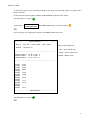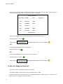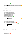
1
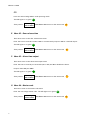
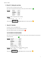
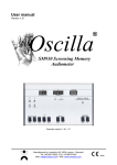
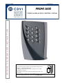
Edition 06/2004
G0301FR0222V01
PROMI 1000
WIRING DIAGRAM AND INSTRUCTION
STAND ALONE ACCESS CONTROL SYSTEM
This device comes with a varistor.
The varistor must be connected on the strike terminal (electromagnet…) operated by the device.
If this product operates more than one strikes, each of them
should have a varistor.
The varistor controls the overload produced by the strike coil –
back emf.
If you are using a « Shear Lock » electromagnetic lock, it is recommended to use a separate power supply than the one connected to the PROMI 1000 !
Edition 10/2003
PROMI 1000
USER MANUAL
I. PRESENTATION DU PRODUIT .................................................................................................................................. 3
A. Product presentation................................................................................................................................ 3
B. Factory Default Values ............................................................................................................................ 4
C. Audible signals .............................................................................................................................................. 4
D. Visual signals ................................................................................................................................................. 4
E. Current consumption ................................................................................................................................ 4
F. Recommended printer.............................................................................................................................. 4
II. PROGRAMMing .......................................................................................................................................................... 6
A. Colors and audible signals ................................................................................................................ 6
B. Main menu .................................................................................................................................................. 6
C. Menu 00 – Program badges and Pin codes ............................................................................ 6
D. Menu 01 – Operating mode ............................................................................................................... 7
E. Menu 02 – Door release time ........................................................................................................... 8
F. Menu 03 – Alarm time output ......................................................................................................... 8
G. Menu 04 – Master code ........................................................................................................................ 8
H. Menu 05 – Setting date and hour .................................................................................................. 9
I.
Menu 06 – Schedules ............................................................................................................................. 9
J. Menu 07 – Holidays ..............................................................................................................................10
K. Menu 08 – Anti pass back .................................................................................................................10
L. Menu 09 – Printer and event ..........................................................................................................10
M. Menu 10 – Badge enrolment unit ................................................................................................12
N. Menu 11 Delete schedules...............................................................................................................13
O. Menu 12 – Delete holidays...............................................................................................................13
P. Menu 13 – Setting accesses during the holidays ................................................................13
Q. Exit from programming ....................................................................................................................14
III. OPERATING INSTRUCTIONS ................................................................................................................................14
A. Reset.............................................................................................................................................................14
B. Operating modes...................................................................................................................................15
C. Lockout .......................................................................................................................................................15
D. Event printing .........................................................................................................................................16
E. Door contact - Alarm..........................................................................................................................16
F. Memory .......................................................................................................................................................17
G. Anti pass – back .....................................................................................................................................17
H. Setting Date and Hour .......................................................................................................................17
V. WIRING DIAGRAM...................................................................................................................................................20
VI. TEMPLATE ..............................................................................................................................................................23
It is recommended to read the user manual to familiarize yourself with all the
features and the operating instructions.
An synoptic is available at the end of the user manual.
The synoptic is usefull to have a general overview on the complete programming
instructions.
2
Edition 10/2003
I. PRESENTATION DU PRODUIT
A. Product presentation
- Input voltage 12V AC/DC
- 12-digit keypad with LED visual indicator
- EPROM memory storage
- Date and hour saving with 3V CR2032 battery
- 1000 programmable proximity badges and Pin codes
- 1000 event stored in memory buffer
- Up to 16 holidays
- Removable memory unit
- RS232 output
- Event thermal printing
- Printing of all events and configuration
- Print badge and code list
- Printer with or without DTR signal (MTP640 Kyoline printer recommended)
- Capability to connect an external reader up to 50 meter
- Anti pass back (PROMI 1000 to exit and reader to enter)
- 1 relay output RT contact 3A/125V~
- 1 alarm relay output N/O contact 3A/125V~
- 3 operating modes:
Mode 0: Badge and Pin code
Mode 1: Badge only
Mode 2: Badge or Pin code
- 3 time zones to operate the 3 operating modes
- 5-digit programmable master code
- Proximity readers and keypad lockout during 2 minutes after 3 invalid Pin code badge
- Buzzer for audible signal
- 1 request-to-exit input
- Door contact input
- Minimum distance of 60 cm between the controller and the reader
3
Edition 10/2003
B. Factory Default Values
Operating mode: 0 badge and Pin code
Door open time: 1 second
Alarm time delay: 00 alarm disabled
Key-in keypad time: 10 seconds
Master code: 12345
No time zone
No Holiday
Anti pass back disabled
DTR signal on for printer
Programming time : 2 minuts
C. Audible signals
1
1
2
4
short beep
long beep
short beeps
short beeps
keypad digit key pressed
Access granted or valid data computing
Start or exit from programming or invalid badge read
Error computing data or badge already programmed
D. Visual signals
LED color
En lecture
En programmation
Orange flashing
Orange
Green
Red
Stand-by
Error computing data
Main menu
Validate computing data
Validate menu
Access granted
Alarm
E. Current consumption
200 mA
F. Recommended printer
MTP 640 KYOLINE
KYOSHA
Paper: thermal, black printer
width 112 mm
diameter 38 mm
4
Edition 10/2003
reference: TP50XSE2C
RS232 with DTR signal (printer on line)
9600 bauds
1 start
Dip switchs set up on the printer
ON
7 bits
Parity: even
1 2 3 4 5 6 7 8
1 stop
IBM mode
40 characters
CR = skip line
DTR signal:
high: printer on line
low: printer off line
Brown
Terminal
White
TX
DT
M
RX
3
Green
2
1
4
5
Yellow
Back side
Paper error:
When paper roll is finished, the printer LED flashes fast, The data is stored in the memory
buffer of the printer until it is full.
Place another paper roll in the printer and press on the feed button until the paper is placed
properly and put back the top cover of the printer, the LED flashed slowly, press promptly on
the feed paper button, the printer starts printing the data stored in its buffer.
The LED stops flashing.
5
Edition 10/2003
II. PROGRAMMING
A. Colors and audible signals
O2
The letter in bolt represents the LED color.
(O for orange, G for green and R for red)
the digit represents the number of beep emitted.
G1
The LED turns green and the 1 beep is emitted.
R1
The LED turns Red and 1 beep is emitted.
B. Main menu
Important: Refer to the one page programming
Enter the master
code twice
O2
Enter the master code twice (12345 default). The LED turns on to orange
and 2 audible beeps are emitted.
A time delay of 2 minutes is set before the main menu is being shut down.
Once in the main menu, the LED lights on in orange.
Enter the 2-digit number of the menu to select a menu (from 00 to 13 )
R1
Once you enter in the menu, the LED lights in red.
Press on the # to exit from programming.
C. Menu 00 – Program badges and Pin codes
Press 00 to enter in badge & Pin code programming menu. The badges and Pin codes are stored in
a slot (pigeon hole) defined as a user number.
Once in the badge programming menu, an automatic search is launch to select the next available
user number.
Once a free user number is selected the LED lights on in Green G1
6
Edition 10/2003
--- Present the badge in front of the PROMI1000 or in front the external reader
(nal reader: see Menu 10)
O1
OR
Select a user number, enter the 3-digit user number from 000 to 999
--- If the user number is available the LED lights on in Green G1 present the badge in front the
PROMI 1000 or in front of the external reader O1
--- If the user number is not available R1 enter another user number or press on * twice G1 to
delete the badge and Pin code.
Then present a badge in front of the PROMI 1000 or external reader.
---------------------------------------------------------------------------------------------------------------------------- Enter the 5-digit Pin code O1
OR
--- Press * to skip the pin code O1
Another search is launch to select an available user number.
------------------------------------------------------------------------------------------------------------------------When all the user numbers are full then the PROMI 1000 displays an error. O4
------------------------------------------------------------------------------------------------------------------------An error is displayed when a badge has been already programmed O4
------------------------------------------------------------------------------------------------------------------------If the printer is connected during the programming then the user number, code of badge and Pin
code are printed.
The last 8-digit of the code of the badge are printed.
D. Menu 01 – Operating mode
Press 01 to enter in the operating mode menu
Press 0 to select Badge & Pin code operating mode.
The LED lights on in green G1
OR
Press 1 to select badge only operating mode.
The LED lights on in green G1
7
Edition 10/2003
OR
Press 2 to select badge OR Pin code operating mode.
The LED lights on in green G1
Press # go
Then press #. back to MENU
The PROMI 1000 returns to the main menu O1
E. Menu 02 – Door release time
Enter 02 to enter in the door release time menu
Enter the time in seconds from 01 to 99 for a momentarily output or 00 for a latched output.
The LED lights on in green G1
Press # go
Then press #. back to MENU
The PROMI 1000 returns to the main menu
O1
F. Menu 03 – Alarm time output
Enter 03 to enter in the alarm time output menu
Enter the time in seconds per 10 seconds (01 to 99 ) and 00 to disable the alarm.
01 pour 10s et 99 pour 990s.
The LED lights on in green G1
Press # go
Then press #. back to MENU
The PROMI 1000 returns to the main menu
O1
G. Menu 04 – Master code
Press 04 to enter in the master code menu
Enter the new 5-digit master code. The LED lights on in green G1
Then press #.
8
Press # go
The PROMI 1000 returns to the main menu O1
back to MENU
Edition 10/2003
H. Menu 05 – Setting date and hour
Enter 05 to enter in the date and hour menu
Enter the hour and minutes then the day, month, year and the week day
Week day:
G1
Monday --------- enter 1
Tuesday -------- enter 2
Wednesday --- enter 3
Thursday ------ enter 4
Friday ---------- enter 5
Saturday ------- enter 6
Sunday --------- enter 7
Example: 09h26, 02 September 2003, Tuesday.
Enter 09 26 02
Then press #.
09
03
2
Press # go
O1
back to MENU The PROMI 1000 returns to the main menu
I. Menu 06 – Schedules
Press 06 to enter in the schedule menu
Each operating mode can be associated with one schedule.
Enter the schedule number of the operating mode
R1
0 for the schedule of the operating mode 0
1 for the schedule of the operating mode 1
2 for the schedule of the operating mode 2
Enter the hour and the minutes for the start time then the hour and the minutes for the stop time
And the week day
G1
Week day: Everyday ---------------- enter 0
Monday ------------------ enter 1
Tuesday ------------------ enter 2
Wednesday ------------- enter 3
Thursday ---------------- enter 4
Friday -------------------- enter 5
Saturday ----------------- enter 6
Sunday ------------------- enter 7
Monday to Friday ------- enter 8
Saturday and Sunday --- enter 9
Example: start time 9h30, stop time 22h50, Monday to Friday.
Enter
09 30
22 50
8
Press # go
Then press#. back to MENU The PROMI 1000 returns to the main menu
O1
9
Edition 10/2003
J. Menu 07 – Holidays
Press 07 to enter in the holidays menu
16 different holidays can be programmed, enter the a holiday number from 01 to 16
R1
Then enter the day and month for this holiday
Example: 25 October, enter 25 10
The LED lights on in green
Then press #.
V1
Press # to go back
to the Main MENU
The PROMI 1000 returns to the main menu
O1
OR
Enter another holiday.
K. Menu 08 – Anti pass back
Press 08 to enter in the anti pass back menu
Press 0 to deactivate the anti pass back mode. Wait 5 seconds for the complete deactivation.
Press 1 to activate the anti pass back. The PROMI 1000 must be used as the exit reader and the
remote reader as the entry reader.
The LED lights on in green
Then press #.
G1
Press # to go back
to the Main MENU
The PROMI 1000 returns to the main menu
O1
L. Menu 09 – Printer and event
Press 09 to enter in the printer setup and event printing menu
Press 0 to delete all the events from the controller
The LED lights on in green
Then press #.
R1
then press # to confirm R1 wait 15 sec
G1
Press # to go back
to the Main MENU
The PROMI 1000 returns to the main menu O1
OR
Press 1 to print all the events stored in the memory buffer G1 then press # to confirm G1
10
Edition 10/2003
To stop the printer at any time keep pressing on the 0 key until the LED lights on in green and a
beep is emitted.
At the end of the printing the a message “END PRINTING” appears on the report.
The LED lights on in green G1
Then press #.
Press # to go back
to the Main MENU
The PROMI 1000 returns to the main menu O1
OR
Press 2 to print the configuration report of the PROMI 1000 control unit.
--------------------------START PRINTING--------------------------Mod 2
DTR off
Touv 01s
Talarm 640s
Mait 12345
Pass back on
------------------------------------------------------------------------Schedule mode 0
Schedule mode 1
Schedule mode 2
12.56 14.23 0
13.19 15.45 3
19.12 22.47 7
Mod = Operating mode
Touv = door release time
Talarm = alarm output time
Master = Master Code
------------------------------------------------------------------------Holiday
Holiday
Holiday
Holiday
Holiday
Holiday
Holiday
Holiday
Holiday
Holiday
Holiday
Holiday
Holiday
Holiday
Holiday
01.01
16.02
01.04
08.05
14.07
15.08
25.10
11.11
31.12
15.12
----------------------------END PRINTING----------------------------
The LED lights on in green G1
OR
11
Edition 10/2003
Press 3 to print all the code of badge and Pin code. To abord the printing report, keep pressing on
the 0 key until the LED lights on in green and a beep is emitted.
--------------------------START PRINTING--------------------------User number Badge
Code
Username
------------------------------------------------------------------------000
022DC567
12458
001
023ABD99
54831
002
023AA1C0
003
023A9305
89657
004
02397F8A
55632
--------------------------END PRINTING--------------------------Only the last 8-digit of the code of the badge are printed on the report.
The LED lights on in green G1
Then press #.
Press # to go back
The PROMI 1000 returns to the main menu
to the Main MENU
O1
OR
Press 4 if the DTR signal is off on the printer.
G1
The LED lights on in green
OR
Press 5 if the DTR signal is on the printer (printer on line)
The LED lights on in green
Then press #.
G1
Press # to go back
to the Main MENU
The PROMI 1000 returns to the main menu O1
M. Menu 10 – Badge enrolment unit
Press 10 to enter in the badge enrolment unit menu
The default badge enrolment unit is the controller built-in reader.
Press 0 to select the controller built-in as the badge enrolment reader, press 1 to select the remote reader as the badge enrolment reader.
12
Edition 10/2003
The LED lights on in green G1
Then press #.
Press # to go back
The PROMI 1000 returns to the main menu
to the Main MENU
O1
To program badges and Pin code selec t Menu 00.
The built-in reader of the controller is set back as the default badge enrolment unit once you exit
from programming.
N. Menu 11 Delete schedules
Press 11 to enter in the delete schedule menu
Enter the schedule of the operating mode to delete
R1
0 to delete schedule of operating mode 0
1 to delete schedule of operating mode 1
2 to delete schedule of operating mode 2
Press on * twice to delete the schedule
Then press #.
Press # to go back
to the Main MENU
G1
The PROMI 1000 returns to the main menu
O1
O. Menu 12 – Delete holidays
Press 12 to enter in the delete holiday menu
Enter the holiday number to delete (from 01 to 16 )
R1
Press * twice to delete the holiday. The LED lights on in green G1
Then press #.
Press # to go back
to the Main MENU
The PROMI 1000 returns to the main menu
O1
OR
Enter another holiday number.
P. Menu 13 – Setting accesses during the holidays
Press 13 to enter in the setting holiday menu
Enter the user number (000 to 999)
The LED lights on in red
R1
13
Edition 10/2003
Press 1 to authorize the access for the selected user number (cardholder) or press 0 to deny access for the selected user number during the holidays.
The LED lights on in green G1
Then press #.
Press # to go back
to the Main MENU
The PROMI 1000 returns to the main menu O1
OR
Press * to authorize the access to all the cardholder O1
Press # to confirm and wait 5s until the new configuration is set for all the cardholder.
The LED lights on in green V1
OR
Press # to deny access to all the cardholder during the holiday periods
O1
Press # to confirm your choice and wait 5 seconds until the new configuration is set for all the
cardholder.
The green LED lights on V1
Then press #.
Press # to go back
to the Main MENU
The PROMI 1000 returns to the main menu O1
Q. Exit from programming
# Exit
You must be in the main menu to exit from programming, press #
O2
Once you exit from programming the PROMI 1000 is on stand-by the LED flashes in orange.
III. OPERATING INSTRUCTIONS
The key-in time between two digit is set at 10 seconds. Behond that time the data computed
is canceled.
A. Reset
Place the ST1 jumper in 2-3 position.
The LED flashes in green during 5 seconds. The default master code is restored to 12345.
14
Edition 10/2003
The LED flashes in red and a beep is emitted.
Remove the jumper from 2-3 position then the unit goes back to stand-by mode.
OR
Keep the jumper on 2-3 position to reset the badges, pin codes, schedules and holidays from
the PROMI 1000 memory.
The LED flashes in red during 5 seconds then the LED lights on in red during the reset.
The LED starts flashing in orange when the reset is completed and a beep is emitted.
Remove the jumper from 2-3 position to go back to stand-by mode.
OR
Keep the jumper on 2-3 position to reset the events.
The LED flashes in orange during 5 seconds then lights on in orange during the reset.
The LED lights off when the reset of all the events is completed.
Remove the jumper from 2-3 position to go back to stand-by mode.
B. Operating modes
--- Mode 0 (badge and Pin code)
Present the badge in front of the PROMI 1000 unit. A beep is emitted when the badge is valid.
Enter the 5-digit pin code. If the Pin code is valid the relay is activated and the access is
granted. Two beeps are emitted to indicate that the badge or Pin code are invalid.
--- Mode 1 (badge only)
Present the badge in front of the PROMI 1000 unit. The access is granted if the badge is valid.
Two beeps are emitted to indicate that the badge is invalid.
--- Mode 2 (badge or Pin code)
Present the badge in front of the PROMI 1000 unit. The access is granted if the badge is valid.
Two beeps are emitted to indicate that the badge is invalid.
OR
Enter the 5- digit Pin code. If the Pin code is valid the access is granted.
C. Lockout
15
Edition 10/2003
After 3 incorrect badge and/or PIN code are entered, the PROMI 1000 reader and the second proximity reader are locked out during 2 minutes and the alarm relay is activated. 2 audible beeps
sound when the badge/PIN code are not valid. The LED lights on in red during the time of the
lockout. The LED flashes in orange when the lockout is finished.
D. Event printing
When a badge is presented or a Pin code is entered, the user number code of badge or Pin Code
date, hour and operating mode are printed.
Valid badge
Invalid badge
User number
Code of badge
Date
Heure
Mode
Rang 521
Badge 022DC567 25.09.03
17.38
2
521
Badge 022DC567
25.09.03
17.38
2
xxx
Badge 0236AD7C
25.09.03
17.40
2
The last 8-digit of the code of the badge are printed.
1000 events are stored in the memory buffer of the controller. The 1001 event replaces the first
one.
E. Door contact - Alarm
The tamper switch activates the relay of the alarm when the front panel is removed. If the alarm
time delay is different to 00, the door monitoring (door ajar or door forced open) is enabled:
When the door is opened, without being activated by the request-to-exit button or a badge, the
alarm relay is activated after 1 second and the red LED lights on (forced open door).
When the badge or the request-to-exit button are used to open a door, if the door stays open, the
open contact will trigger the alarm relay according to the door relay output.
Momentary output
The alarm time delay begins at the end of the door release time. If the door is maintained open
after the alarm time delay, the alarm relay is activated and the red LED lights on. Closing back the
door will deactivate the alarm relay and the LED start flashing orange.
Latched output
The alarm time delay begins only when the door stays open after ordering the closing by presenting back the badge or pressing on the request-to-exit button, the alarm relay is activated and the
red LED lights on. Closing back the door will deactivate the alarm relay and the LED flashes orange.
16
Edition 10/2003
Note:
1. During an alarm the reader and the request-to-exit are enabled.
2. To cancel the alarm go to Menu 03 in programming and enter 00.
Events
Quand l’alarme est commandée (forced door open, door ajar or lockout alarm) the following
messsages are printed on the event report «Alarm» and «Alarm end» with the day and hour of
the event.
Event
Alarm
Alarm cleared
Date
25.09.03
25.09.03
Heure Mode
17.38
17.44
2
2
F. Memory
The memory unit on the PROMI 1000 can be removed. The time outputs, the schedules, the holiday periods, the badges, the Pin codes and the events are stored in the memory unit.
All the data on the memory
G. Anti pass – back
To start the anti passback mode go to menu 08. The PROMI 1000 must used as an exit unit and the
remote reader as the entry reader.
It is important to present the badge on the entry reader and on the exit reader. The access is
granted only when the badge was presented on the exit reader.
H. Setting Date and Hour
The PROMI 1000 has a buit-in clock calender with time and date. The clock must always be
powered by the 12V power supply or the 3V CR1225 battery.
The battery is used only in case of power failure.
17