1
USER MANUAL
AD11030 Bio Controller
Firmware Version 2.2X, March 1999
BIO CONTROLLER
AD11030
USER MANUAL
appiKon8
DEPENDABLE INSTRUMENTS
V1UECE0012b
CE CONFORMITY
EU DECLARATION OF CONFORMITY
The company Applikon Dependable Instruments B.V.,
Schiedam, The Netherlands, hereby certifies that the
instrument:
AD11030 BIO CONTROLLER
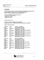
meets the requirements of the EU Directives 89/336/EEC
(Electromagnetic Compatibility) and 73/23/EEC (Low
Voltage).
SOURCE OF THE SPECIFICATIONS:
89/336/EEC:
73/23/EEC
EN 50081-1 (1992) EMC Generic emission standard.
Residential, commercial and light industry.
EN 61000-3-2 (1995) EMC Limits for harmonic current
emissions (equipment input current < 16A per phase).
EN 61000-3-3 (1995) EMC Limits concerning voltage
fluctuations and flicker for equipment having an input current up
to and including 16 A per phase.
EN 50082-1 (1992) EMC Generic immunity standard.
Residential, commercial and light industry.
EN 50082-2 (1995) EMC Generic immunity standard. Industrial
environment (including table A.4).
EN 61010 Safety requirements for electrical equipment for
measurement, control and laboratory use.
ing J. van Burg, President.
Applikon Dependable Instruments
3125 AE Schiedam
Tel.:(31)(0)10-2983555
21.08.96
De Brauwweg 13
The Netherlands
Fax.: (31)(0)10-4379648
appiiKorf
DEPENDABLE INSTRUMENTS
USER MANUAL
AD11030 Bio Controller
CO NTE
Firmware V2.2x, March 1999
TABLE OF CONTENTS
Chapter
Description
Page
Introduction and Main Menu
1-1
Process Menu
Process Control
2.1.1 Individual Variable Selection
2.1.2 General Variable Selection
Process Setpoint
Process Display
2.3.1 Display Dose Monitor Values
2.3.2 Display Outputs
2.3.3 Display Process Time
2.3.4 Display Setpoints
2.3.5 Display Controller Outputs
2-1
2-2
2-2
2-3
2-4
2-5
2-5
2-6
2-7
2-7
2-8
3.2
3.3
3.4
Manual Menu
Manual Calibration
3.1.1 pH Calibration
3.1.2 Temp. Calibration
3.1.3 dO2 Calibration
3.1.4 dCO2 Calibration
3.1.5 Level Calibration
3.1.6 mV/mA Calibration
Reset Dose Monitor Values
Manual Outputs
Manual Print
3-1
3-2
3-3
3-4
3-6
3-7
3-7
3-8
3-9
3-10
3-11
4
Parameter Menu
4-1
5
5.1
Configuration Menu
Configuration Setup
5.1.1 Controller Definitions
5.1.1 Alarm Defintions
5.1.3 Timer Definitions
5.1.4 Recording Definitions
5.1.5 Manual Definitions
5-1
5-2
5-2
5-8
5-11
5-12
5-15
2
2.1
2.2
2.3
3
3.1
appiikorf
DEPENDABLE INSTRUMENTS
NTS
USER MANUAL
MAIN MENU
ADI 1030
Firmware V2.2x, March 1999
CHAPTER 1
INTRODUCTION
AND MAIN MENU
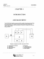
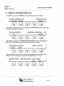
The ADI 1030 Bio Controller is a process controller, capable of measuring and controlling
up to four parameters. The controller contains an 8-bit micro processor, loaded with
flexible firmware that can control four parameters through eleven outputs (nine solid state
and two analog outputs).
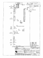
See figure below:
D
RS232 '
G
A
Schematic configuration of the Bio Controller ADI 1030
A = Controller Board ADI 1030
C = LCD Display
E = Digital Outputs (9x)
G = Bio Process
B = Keyboard
D = Analog Outputs (2x)
F = Sensor Modules (4x)
H = Host Computer
1-1
DEPENDABLE INSTRUMENTS
USER MANUAL
MAIN MENU
ADI 1030
Firmware V2.2x, March 1999
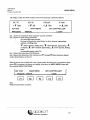
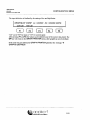
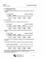
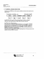
The display of the ADI 1030 consists of four lines (example is presented below):
36.7°C
29.3%
6.50 pH
0.3 bar
f T 25%
3 T 5%
6 £.75%
11 A. 25%
MAIN MENU
AD11030
PROCESS
BIO CONTROLLER
MANUAL
LOGIN
line 1 shows the (maximum four) measured "process variables",
line 2 shows for each running controller:
the controlled output number,
the trend of the process value (below or above setpoint, approaching
setpoint or drifting away:
• : below setpoint, drifting away, 1 : below setpoint, approaching, ~i :
at setpoint, J _ : above setpoint, approaching, J L : above setpoint, drifting
away,
the controller output value (%).
line 3 showes the menu line of the firmware.
line 4 showes the functions of the function keys F1 through F5 (these functions depend
on the selected menu, see line 3).
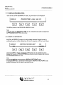
When de power was switched off in the "logout-mode" and the power is switched on again
(press F 3 to continue), the lowest two display lines show the MAIN MENU status and
the available MENU FUNCTIONS:
ADI 1030
PROCESS
F1
-
MAIN MENU
BIO CONTROLLER
MANUAL
F2
LOGIN
F3
F4
F5
Note:
• Shaded function keys are active.
L.-: appiikorf
DEPENDABLE INSTRUMENTS
1-3
USER MANUAL
PROCESS MENU
ADI 1030
Firmware V2.2x, March 1999
CHAPTER 2
PROCESS MENU
After accessing the PROCESS menu (use F1 in the MAIN menu), the lowest two
display lines show:
PROCESS:
SELECTACTION
CONTROL
SETPOINT
DISPLAY
F1
F2
F3
F4
F5
The functions in this menu are explained in the following paragraphs.
The UP or the MAIN key will return to the MAIN menu.
The FREEZE key can be used to freeze active control loops; display message:
PROCESS: FREEZE
SELECT CONTROL LOOP
•VAR#1"
"VAR#2"
'VAR#3"
F1
F2
F3
I
VAR#4"
F4
ALL
F5
The function keys F1 through F4 can be used to freeze one of the (active) loops; F 5 can
be used to freeze all loops at the same time.
Function keys of loops that are not active are not presented.
When one (or more) control loops are frozen, the PROCESS: CONTROL: menu will
contain the UNFREEZE option (see chapter 2.1.1 and 2.1.2)
When no control loops are started (active), the FREEZE-function can not be used (error
message "NO ACTIVE CONTROL LOOP").
appiikorr
DEPENDABLE INSTRUMENTS
2-1
USER MANUAL
PROCESS MENU
ADI 1030
Firmware V2.2x, March 1999
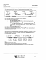
2.1.2 GENERAL VARIABLE SELECTION:
With function key F5 (ALL), all four process variables are selected at the same time; the
display shows:
PROCESS: CONTROL: ALL:
START
F1
(STOP)
F2
"PROCESS TIME"
(UNFREEZE)
T-START
F3
F4
T-RESET
F5
With F1/F2, control loops of all four process variables are started or stopped.
When one or more control loops are frozen, F 3 can be used to undo this.
Key F4 has three different functions:
• If the process time = 0000:00:00 (HHHH:MM:SS) and not running, F 4 = T-START
(pressing this key will start the process time counter); in this case, F 5 has no function.
• If the process time is not 0000:00:00 and not running, F4 = T-CONT. and F5 = TRESET; F4 will continue the process time counter, F5 will reset the process time to
0000:00:00 (conformation is requested first).
• If the process time is running, F 4 = T-STOP (pressing this key will stop the process time
counter); in this case, F5 has no function.
cppiiKorf
DEPENDABLE INSTRUMENTS
2-3
USER MANUAL
PROCESS MENU
ADI 1030
Firmware V2.2x, March 1999
2.3 PROCESS-DISPLAY:
After selecting F 3 in the P R O C E S S menu, the display presents:
PROCESS: DISPLA Y:
SELECT OPTION
DOSED
OUTPUTS
PTIME
F1
F2
F3
SETPOINT
F4
CONTROL
F5
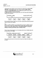
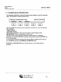
2.3.1 DISPLAY DOSE MONITOR VALUES:
After selecting F 1 , three groups of recorded values of dose monitor-outputs (1 - 3; 4 - 6
and 7 - 9 ) can be selected:
PROCESS:DISPLAY:DOSE MONITORS:
(1-3)
(4-6)
(7-9)
F1
F2
F3
F4
F5
The function keys are used to select a group; pressing F1 will result in the following
display:
DM(1-3)
F1
XXXX.X"xxx" XXXX.X"xxx"
(4-6)
(7-9)
F2
F3
XXXX.X"xxx"
F4
F5
After use of key F2 or F 3 , key F1 will select Dose Monitors 1-3.
• The dose monitor values can be configured (see chapter 5) to present values in the
following dimensions:
time (mn or hs),
volume (ml or 1),
weight (g or kg),
power (J or kJ).
The dose monitor values are presented with floating point.
When a dose monitor value reaches 99999, it will be reset to 0.
2-5
DEPENDABLE INSTRUMENTS
USER MANUAL
PROCESS MENU
ADI 1030
Firmware V2.2x, March 1999
2.3.3 DISPLAY PROCESS TIME:
After selection of F3 in the DISPLAY menu, the process time will be displayed:
DISPLAY:
F1
PROCESS TIME: HHHH: MM: SS
F2
F3
F4
F5
The UP key returns to the PROCESS-DISPLAY menu.
Note:
- Using this menu, the PROCESS TIME can only be recalled, not started or stopped (see
the PROCESS-CONTROL-ALL menu).
2.3.4 DISPLAY SETPOINTS:
Key F4 in the DISPLAY menu can be used to change the normal display lay-out; by
enabling this option, the third display line will show the setpoints of all four control loops:
DISPLAY:
SETPOINT ON 3RD LINE?
YES
F1
NO
CONFIRM
F2
F3
F4
F5
After pressing F1 its function will change in NO; in this way the required lay-out of
display line 3 can be set. F5 (CONFIRM) key activates the selected option and returns to
the PROCESS-DISPLAY menu.
Note:
• Pressing the MAIN key will activate the DISPLAY-SETPOINT mode.
• Pressing the MAIN key a second time will interrupt the DISPLAY-SETPOINT mode
and the third display line will return to its normal lay-out.
appiikorf
DEPENDABLE INSTRUMENTS
2-7
USER MANUAL
MANUAL MENU
ADI 1030
Firmware V2.2x, March 1999
CHAPTER 3
MANUAL MENU
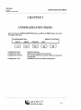
After accessing the MANUAL menu (use F2 in the MAIN menu), the lowest two display
lines show:
MANUAL:
CALIBR
F1
SELECT ACTION
D RESET
OUTPUTS
F2
F3
PRINT
F4
F5
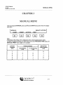
Note:
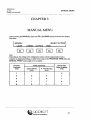
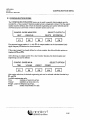
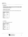
• Depending on the setting in the configuration menu, (serial communication with a
computer or graphical printing, see table below) and on the PROCESS TIME status, the
MANUAL-PRINT menu might not be available.
Computer
Connected
(Y/N)
Printer Connected
Manual Print
Option Available
(Y/N)
Graph Defined
(Y/N)
P. Time Running
(Y/N)
Y
-
-
N
N
N
N
Y
N
Y
N
Y
N
Y
Y
N
N
N
Y
Y
Lappikorf
DEPENDABLE INSTRUMENTS
3-1
USER MANUAL
MANUAL MENU
ADI 1030
Firmware V2.2x, March 1999
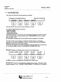
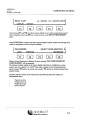
3.1.1 P H CALIBRATION:
After selection of pH, the following options are available:
MANUAL:CALIBRATION:pH
SELECT OPTION
EXECUTE
DATA
DEFAULT
CORRECT
F1
F2
F3
F4
F5
After pressing F 1 , the actual (two point) calibration is started.
In a cycle, the following data is requested:
- BUFFER TEMP,
- FIRST BUFFER,
- SECOND BUFFER,
The buffer temperature is used for the Nernst potential correction; after entering a buffer
value, the sensor signal is scanned (display shows "MEASURING") until it is stable
(drift<0.02pH/6sec).
If a calibration is executed once, the used buffer values are supposed to be default.
With help of these values and the two measured electrode signals, the calibration
parameters are calculated: SLOPE (in relation to the Nernst potential) and OFFSET
(differance from pH 7 at 0 mV) of the electrode.
At the end of the calibration procedure, the slope and offset are displayed at line three for
five seconds (the UP key returns to the MANUAL-CALIBRATE menu).
F2 (DATA) displays the calibration data on the two lower display lines:
CALIB: "VAR#": SLOPE
X.XXX
F1
F2
OFFSET
VALUE1
XX.XX
XXX.XX
F3
VALUE2
XXX.XX
F4
F5
The UP key returns to the MANUAL-CALIBRATE-"VAR#" menu.
F3 (DEFAULT) resets the calibration data to default values: slope = 1.00, offset = 0.00
(display message for 5 sec: "CALIBR "VART RESET TO DEFAULT VALUES").
, . appiikort
DEPENDABLE INSTRUMENTS
3-3
USER MANUAL
MANUAL MENU
ADI 1030
Firmware V2.2x, March 1999
3.1.2 CALIBRATION OF TEMPERATURE:
The temperature calibration is required to ensure accurate readings over the full measuring
range. The temperature calibration display shows:
MANUAUCALIBRA TlON:Temp
EXECUTE
F1
DATA
DEFAULT
F2
F3
SELECT OPTION
F4
F5
After pressing F 1 , the actual (two point) calibration is executed. In a cycle, the following
data is requested:
- FIRST VALUE,
- SECOND VALUE,
After entering a temperature value, the sensor signal is scanned (display shows
"MEASURING") until it is stable (drift < 0.2°C / 6 sec).
With help of these values and the two measured electrode signals, the calibration
parameters are calculated: SLOPE (in relation to the theoretical slope) and OFFSET (at
0 °C) of the electrode.
At the end of the calibration procedure, the slope and offset are displayed at line three (5
sec). The UP key returns to the MANUAL-CALIBRATE menu.
F2 (DATA) and F3 (DEFAULT) have the same function as in the pH calibration
procedure.
3-5
DEPENDABLE INSTRUMENTS
USER MANUAL
MANUAL MENU
AD11030
Firmware V2.2x, March 1999
3.1.4 dCO2 CALIBRATION:
After selection of the dCO2 calibration menu, the following options are available:
MANUALCALIBRA TION:dCO2
EXECUTE
DATA
DEFAULT
F1
F2
F3
SELECT OPTION
F4
F5
After pressing F 1 , the actual (two point) calibration is started.
Apart from the possibility to specify the buffer temperature, the dCO2 calibration
procedure is identical to the pH calibration.
Refer to the calibration instructions that come with the electrode.
F2 (DATA) and F 3 (DEFAULT) have the same function as in the pH calibration
procedure.
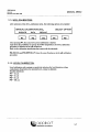
3.1.5 LEVEL CALIBRATION:
Level calibration only contains a sensitivity selection for level detection; when
conductance drops below the selected level, contact is detected.
Possible selections:
F 1 = 10MS,
F 2 = 15 yuS,
F3 = 23 MS,
F4 = 100 A^S,
3-7
DEPENDABLE INSTRUMENTS
USER MANUAL
MANUAL MENU
ADI 1030
Firmware V2.2x, March 1999
3.2 RESET DOSE MONITOR VALUES:
In the RESET DOSE MONITOR menu, lines three and four of the display are
presented in the following manner:
MANUAL-RESET DOSE MONITORS:
ALL
SELECT
F1
F2
F3
F4
F5
After selection of F 1 , a confirmation is requested before all dosed values are reset:
RESET ALL DOSED VALUES?
YES
F1
NO
F2
F3
F4
F5
In case F1 is pressed, all dosed values are reset (set to 0); pressing F 5 will return to the
previous menu.
After selection of F2, the display shows the lowest output number that is defined as dose
monitor:
RESET DOSED VALUE: OUTPUTS
NEXT
F1
X.XXX "UNITS"
PREVIOUS
F2
RESET
F3
F4
F5
F2 is functional after pressing F1 once. Pressing F 5 will reset the dose monitor value to
0. When the highest output number is displayed, F1 has no function.
If no output is defined as dose monitor, the error message." NO DOSE
MONITORS
DEFINED is generated.
The UP key will return to the MANUAL menu.
3-9
DEPENDABLE INSTRUMENTS
USER MANUAL
MANUAL MENU
ADI 1030
Firmware V2.2x, March 1999
3.4 MANUAL-PRINT:
In case in the CONFIGURATION-SERIAL menu the printer option is selected, F4 in
the MANUAL menu can be used to select manual print-outs:
MANUAL: PRINT
SELECT A CTION
STATUS
INTERVAL
F1
¥2
CONFIG
PARAM
F3
F4
F5
Note:
- In case the non-graphical printer mode is configured, manual print commands are valid at
any time.
- In case the graphical printer mode is configured, manual print commands can only be
issued when the Process Time counter is not running; in case the Process Time counter is
running, the MANUAL-PRINT menu is not accessable (see also the table at page 3-1).
F1 (STATUS) generates a print-out of all input and output values (measured process
variables, controller outputs, dose monitor values, analog outputs).
F2 (INTERVAL) will generate the same list of all input and output values periodically;
the interval time must be set in minutes. Interval printing is deactivated by setting the
interval time to 0 min.
F3 (CONFIG) generates a print-out of the configuration (per control loop: name and
controller output## (normal and additional), alarm limits and output; also undefined or
manual defined outputs are listed.
F4 (PARAM) generates the listing of all parameter settings of the four control loops.
Note:
• After entering a printer command, the message "XXXXXXXX:PRINTING" will be
displayed for a 3 sec. period.
• In case the connected printer is not ready for data transfer (X-off) for an uninterrupted
period of 2 minutes, a printer time-out message will be generated.
3-11
DEPENDABLE INSTRUMENTS
USER MANUAL
PARAMETER MENU
ADI 1030
Firmware V2.2x, March 1999
CHAPTER 4
PARAMETER MENU
After accessing the PARAMETER menu (use F 3 in the MAIN menu), the lowest two
display lines show:
PARAMETER:
SELECT VARIABLE
"VAR#1"
"VAR#2"
"VAR#3"
F1
F2
F3
"VAR#4"
F4
F5
After selection of the required process variable, the display shows:
PARAMETER: "VAR#"
INPUT
CONTROL
F1
F2
SELECT PARAM TYPE
F3
F4
F5
After selection of F 1 , the input parameters are presented; after selection of F2, the control
parameters are presented. Display (in case of control par.):
PARAMETER: "VARW
P-GAIN: XXX.XX
NEXT
PREVIOUS
F1
F2
EDIT
F3
F4
F5
F2 only has the function PREVIOUS after pressing F1 once; when the final parameter
is reached, F1 becomes functionless.
After pressing F 5 (EDIT), the parameter value can be updated with the numerical keyboard; the menu now remains in the EDIT mode until the UP or ENTer key is issued.
lu-: appiikorf
DEPENDABLE INSTRUMENTS
4-1
USER MANUAL
CONFIGURATION MENU
AD11030
Firmware V2.2x, March 1999
CHAPTER 5
CONFIGURATION MENU
After accessing the CONFIGURATION menu (use F4 in the MAIN menu), the lowest
two display lines show:
CONFIGURA TION:
SELECT OPTION
SETUP
SERIAL
DOSE MN
F1
F2
F3
Configuration Setup:
Configuration Serial:
Configuration Dose Mn:
Configuration View:
VIEW
F4
F5
hardware definition.
definitions and setting of the serial port.
dose monitor definition of actuators that are connected to
control loops.
possibility to recall the defined configuration.
ii appiiKorf
DEPENDABLE INSTRUMENTS
5-1
USER MANUAL
CONFIGURATION MENU
ADI 1030
Firmware V2.2x, March 1999
The proposed output number is the one with the lowest number that is undefined (F5 =
DEFINE) or already defined in this control loop in cascade order (F5 = EDIT).
The function of F2 (PREVIOUS) is only available after use of F 1 ; when no extra
outputs are available, F1 becomes functionless.
Key F5 defmes/edits the proposed output number, after which the position regarding the
setpoint must be specified:
PLACE OUTPUT ##
CONTROL:"VAR#"
SP
Ft
F2
F3
F4
F5
F1 will define the selected output to be active below setpoint, F2 will define the selected
output to be active above setpoint.
Note:
• In case of LEVEL CONTROL, the controller definition procedure is different, since in
this case only one output can be defined, editted or deleted. After selecting the output
number, the only other available selection is "NORMAL/INVERSE11 as a manner of
defining the actuator type (Normally Open or Normally Closed).
The next step is only presented in case of an analog output (in case of digital outputs, the
next step will be: LOW LIMIT).
CONTROL:"VAR#":AO#: "UNITS"
OUTPUT%
F1
AGITATN
FLOWRTE
F2
F3
SELECT OPTION
POWER
F4
UNDEF
F5
The engineering units that can be selected for each option, are listed in the table on the
next page.
5-3
DEPENDABLE INSTRUMENTS
USER MANUAL
CONFIGURATION MENU
ADI 1030
Firmware V2.2x, March 1999
After entering numeric values for the limits, the cycle time of the selected output must be
entered (only in case of digital outputs):
CONTROL:"VAR#":
CYCLE TIME:
XXXXX sec
CONT
F1
F2
F3
F4
EDIT
F5
Use the numeric keyboard to enter this value.
Now the output can be defined to be a Normal or Inverse output (Inverse output means:
Actuator Output = 100% when process value is at setpoint):
CONTROL "VAR#":
OUTPUT ## NORMAL
CONFIRM
INVERSE
F1
F2
F3
F4
F5
F1 toggles between NORMAL and INVERSE. After the Normal/Inverse definition of
the output, the output configuration is finished; the configured output can be edited (see
page 5-7) or an additional output can be configured by returning to the
CONFIGURATION-SETUP-CONTROL menu.
DANGER: INVERSE definition of an output means
that the actuator output is 100% when the process
value is at setpoint or the control loop is not running.
Before INVERSE definition of an output, disconnect
the power supply of the output module of the ADI
1030. Do not reconnect this power supply of the
output module before alle precautions are taken to
prevent any accidents.
applikorf
DEPENDABLE INSTRUMENTS
5-5
USER MANUAL
CONFIGURATION MENU
ADI 1030
Firmware V2.2x, March 1999
EDITTING AND/OR DELETING OUTPUTS FROM A CONTROLLER
SETUP:
If a controller setup (outputs assignment or corresponding data) needs to be updated, this
can easily be done according to the following procedure.
Enter the SETUP-CONTROL and select the corresponding process variable (control
loop):
CONTROL: "VAR#"
OUTPUT: ##
NEXT
PREVIOUS
F1
F2
DELETE
F3
F4
EDIT
F5
Use F1 and/or F2 until the output is displayed that should be updated or deleted.
In case F5 (EDIT) is selected, the definition procedure is followed (same procedure as in
case of the original setup definition) and each definition/setting can be editted.
In case F4 (DELETE) is selected, the specified output is deleted from the Controller
Setup Definition. After deleting an output by using F4, the display message "OUTPUT
# # DELETED" is displayed (line 3; 5 sec. interval), after which will be returned to the
Setup Control "Var#" menu.
*>, appikorf
DEPENDABLE INSTRUMENTS
5-7
USER MANUAL
CONFIGURATION MENU
ADI 1030
Firmware V2.2x, March 1999
The proposed output number (only digital outputs) is the one with the lowest number that
is still undefined (F5 = DEFINE) or already defined as an alarm output (F4 =
DELETE).
The function of F2 (PREVIOUS) is only available after use of F 1 ; when no extra
outputs are available, F1 becomes functionless.
Key F5 defines the proposed output number as an alarm output.
If no outputs are available for alarm definition, an error message is generated.
F2 (DISPLAY): in case of an occurring alarm, the alarm message is presented on display
line 3; F3 is used for acknowledge-purposes.
ALARM:"VAR#":LOW/HIGH:
TO DISPLAY:
YES
F1
NO
CONFIRM
F2
F3
F5
F4
F1 toggles between YES and NO. F5 confirms the selected action.
With F3 (FREEZE), the alarm status can be defined to Freeze the control loop:
ALARM:"VAR#":LOW/HIGH:
FREEZE:
YES
F1
NO
CONFIRM
F2
F3
F4
F5
F1 toggles between YES and NO. F5 selects the required action.
Note:
• In case an output is frozen because of an alarm, this Freeze status can be reset with help of
the Process-Control menu.
&:> appiikorf
DEPENDABLE INSTRUMENTS
5-9
USER MANUAL
CONFIGURATION MENU
ADI 1030
Firmware V2.2x, March 1999
5.1.3 TIMER DEFINITIONS:
The function key F3 (TIMER) in the CONFIGURATION SETUP is used for Timer
definitions (a timer is a manual controlled output). Display:
SETUP TIMER:
OUTPUT #
NEXT
PREVIOUS
F1
F2
DELETE
F3
F4
EDIT/DEFINE
F5
The proposed output number is the one with the lowest number that is still undefined (F5
= DEFINE) or already defined as a timer output (F4 = DELETE, F5 = EDIT).
The function of F2 (PREVIOUS) is only available after use of F 1 ; when no extra
outputs are available, F1 becomes functionless.
Key F5 selects the proposed output number as a timer output; in case the output number
was already defined as a timer, function key F4 can be used to delete this timer definition.
If no outputs are available for timer definition, an error message is generated.
Now the timer data must be set (HH:MM:SS):
SETUP TIMER #:
F1
F2
XXXXXX
XXXXXX
XXXXXX
DELAY
ON
OFF
F3
F4
F5
The UP key is used to return to the SETUP TIMER menu.
Note:
• Periods between 60 and 100 seconds are illegal and must be specified as 1 minute and a
number of seconds.
• The timer function is an action that is manually defined; in the configuration menu, a
delay-time, an on-time and an off-time can be set. In the MANUALOUTPUTS menu
the Timer can be started or stopped. After starting a Timer, first the programmed Delay
time will elapse, after which a continuous cycle of On- and Off-times will occur.
appikorf
DEPENDABLE INSTRUMENTS
5-11
USER MANUAL
CONFIGURATION MENU
ADI 1030
Firmware V2.2x, March 1999
LL=XXXXX
REC#: "VAR":
LOW LIM
HGH LIM
F1
F2
F3
HL = XXXXX UNITS
F4
F5
After pressing F1 and F2, the values can be editted by use of the numerical key-board.
After setting the limits, the UP key is used to return to the SETUP RECORDER
menu.
When DOSE MN is selected, the dose monitor (digital output) number and the high limit
(value to correspond to 20 mA) must be defined.
RECORDERS
NEXT
SELECT DOSE MONITOR: #
PREVIOUS
F1
F2
EDIT/DEFINE
F3
F4
F5
When no Dose Monitors are defined, the error message "NO DOSE MONITOR
CONFIGURED" will be generated.
The proposed output number is the lowest digital output that is configured as a dose
monitor (see also chapter 5.3); with F1 the output number can be incremented (only
digital outputs). F 5 selects the actual dose monitor. F4 deletes an already selected dose
monitor output.
The dose monitor values can be expressed in the following units (see chapter 5.3:
configuration dose):
Time (hs or mn),
Volume (ml or 1),
Weight (g or kg),
Power (J or kJ).
5-13
DEPENDABLE INSTRUMENTS
USER MANUAL
CONFIGURATION MENU
ADI 1030
Firmware V2.2x, March 1999
5.1.5 MANUAL DEFINITIONS:
An analog output can also be configured for manual operation; in this case, the output
value can be manually controlled.
In this case, the following data must be specified:
- the engineering units of the available options (see table below),
- the maximum value that can be obtained (corresponds to 20 mA),
- the low limit of this output,
- the high limit of this output.
SETUP MANUAL: ANALOG 1
ANALOG2
F1
DELETE
F2
F3
EDIT/DEFINE
F4
F5
Key F1 toggles between ANALOG2 and ANALOG 1. (In case one of the analog outputs
is configured in the RECORD mode, only one output remains; when both analog outputs
are configured in the R E C O R D mode, the error message: NO ANALOG
AVAILABLE is generated).
If an analog output was already defined as manual, the EDIT key can be used to change
the maximum value, low and high limit values of this output.
F5 defines the actual selection. If the analog output is already configured for manual
operation, it can be edited or deleted.
Next the desired option must be specified:
MANUALS
SELECT OPTION
AGITATN
FLOWRTE
F1
F2
UNDEF
F3
F4
: appikorf
DEPENDABLE INSTRUMENTS
F5
5-15
USER MANUAL
CONFIGURATION MENU
ADI 1030
Firmware V2.2x, March 1999
5.2 CONFIGURATION SERIAL:
This menu is used to define the type and settings of serial communication:
CONFIG:SERIAL:
INTERF
-F1
SELECT OPTION
SETTINGS
CONNECT
F2
F3
F4
F5
Note:
• Information about the Applikon communication protocol and function codes to perform
serial communication can be found in the ADI 1030 Serial Communication Manual.
5.2.1 INTERFACE SELECTION:
In case F1 is selected in the SERIAL menu, the following menu is presented:
CONFIG:SERIAL:INTERF:
RS232
F1
RSXXX
RS422
RS485
F2
F3
CONFIRM
F4
F5
With function keys F1 through F 3 , followed by F5, an interface type can be selected.
Default interface selection is RS232; in case one of the other interfaces is selected, printerfunctions are not longer valid.
However, if in the CONNECT menu the option PRINTER is selected, the options
R S 4 2 2 and R S 4 8 5 are not present since the printer cannot communicate with these
types of interfaces.
Note:
• If serial communication, using RS442/RS485 is required, the switch-positions 1, 2 and 3
at the controller board of the ADI 1030 must be altered. Refer to the Installation Manual
of the ADI 1030 Bio Controller, chapter 1.3.5: Serial Communication.
i U *~-
5-17
DEPENDABLE INSTRUMENTS
USER MANUAL
CONFIGURATION MENU
ADI 1030
Firmware V2.2x, March 1999
5.2.3 PRINTER / COMPUTER CONNECTION:
In case F3 is selected in the SERIAL menu, the following menu is presented:
xxxxxxxxxxx
SERIALCONNECTION:
COMPUTER
CONFIRM
PRINTER
F3
F2
•-F1
m
F4
With function key F2, followed by key F5, the option PRINTER is selected, after which
the following message is presented:
GRAPHICAL PRINTING?
SERIAL-PRINTER:
YES
NO
CONFIRM
F2
F1
F3
F4
F5
When NO is confirmed, the CONFIGURATION-SERIAL menu is presented again.
When YES is confirmed, the graphical printing mode must be defined:
GRAPHICAL PRINTER:
GRAPH
SELECT OPTION
EVENT
F1
F2
F3
F4
F5
After selecting F 1 , the trend of six signals can be configured; however, first the time
(HH:MM) per 20 cm paper feed must be selected (default value = 12 hours):
GRAPH PRINT:
TIME PER 20 CM: XXXX HHMM
CONT
F1
F2
F3
F4
EDIT
F5
5-19
DEPENDABLE INSTRUMENTS
USER MANUAL
CONFIGURATION MENU
ADI 1030
Firmware V2.2x, March 1999
The input definition is finalized by the setting of low and high limits:
GRAPH#:XX "VAR#": LL = XXXXX HL = XXXXX UNITS
LOW LIM
HGH LIM
F1
F2
F3
F4
F5
"XX" can be "IN" for input or "CO" for control signal.
After pressing F1 and F2, the values can be editted by use of the numeric key-board. The
UP key will return to the GRAPH PRINTER menu; other graph# can now be defined.
If the sixth was just defined, the GRAPH PRINTER generates the message: "6
GRAPHS DEFINED".
5-21
DEPENDABLE INSTRUMENTS
USER MANUAL
CONFIGURATION MENU
ADI 1030
Firmware V2.2x, March 1999
After output selection, the low and high limits must be specified (same procedure as for
inputs):
GRAPH#: AO1/2 LL = XXXXX
LOW LIM
HGH LIM
F1
F2
HL = XXXXX UNITS
F4
F3
F5
If F4 (DOSE MN) is selected, a dose monitor function can be assigned to the solid state
outputs and be recorded (see also 5.1.4: recording definitions).
GRAPH#:
NEXT
F!
SELECT DOSE MN: #
PREVIOUS
F2
CONFIRM
F4
F3
F5
The proposed output number is the lowest digital output that is defined as a dose monitor;
with F1 the output number can be incremented (only digital outputs). F 5 defines the
actual selection.
Now the high limit must be specified:
GRAPH#:DOSE MN #
HIGH LIMIT:
XXX.XX "UNITS"
CONT
F1
F2
F3
F4
EDIT
F5
The high limit of the dose monitor can be entered, using the numeric key-board.
The UP key returns to the GRAPH PRINTER menu. Pressing the U P key again will
return to the GRAPHICAL PRINTER menu.
.• appiikorf
DEPENDABLE INSTRUMENTS
5-23
USER MANUAL
CONFIGURATION MENU
AD11030
Firmware V2.2x, March 1999
5.3 CONFIGURATION DOSE:
The CONFIGURATION-DOSE menu can be used to specify which outputs must be
recorded by a "dose monitor" function (output action is integrated in time). First the output
number must be defined, after which the desired engineering unit can be selected and the
conversion factor (conversion of time to actuator action) can be set:
CONFIG: DOSE MONITOR
NEXT
PREVIOUS
F1
F2
SELECT OUTPUT #
DELETE
m
F3
EDIT/DEFINE
F5
The proposed output number is 1; with F1 the output number can be incremented (only
digital outputs). F 5 defines the actual selection.
If the actual output # is already defined as a dose monitor, the edit and delete option are
displayed (F4 and F5).
After selecting an output number for a dose monitor function, the desired option and
engineering unit can be defined:
CONFIG: DOSE MN #:
TIME
F1
SELECT OPTION
VOLUME
WEIGHT
F2
F3
POWER
F4
F5
After option selection, the desired engineering unit can be selected with the function keys
F1 and F2.
Available engineering units:
Time
: minutes or hours (mn or hs),
Volume
: milliliters or liters (ml or 1),
Weight: grams or kilograms (g or kg),
Power
: Joules or kilo Joules (J or kJ).
i£ appiikorf
DEPENDABLE INSTRUMENTS
5-25
USER MANUAL
CONFIGURATION MENU
ADI 1030
Firmware V2.2x, March 1999
5.4 CONFIGURATION VIEW:
The CONFIGURATION-VIEW menu can be used to recall the different configuration
definitions.
SELECT OPTION
CONFIG.VIEW:
INPUT
OUTPUT
F1
F2
F3
F4
F5
5.4.1 VIEW INPUT:
In the VIEW-INPUT menu first the process variable must be selected:
VIEW INPUT:
SELECT OPTION
"VAR1"
"VAR2"
F1
F2
"VAR3"
"VAR4"
F3
F4
F5
After selection of the required process variable, the following three options can be
selected:
SELECT OPTION
VIEW "VAR#":
CONTROL
ALARM
RECORD
F1
F2
F3
F4
F5
If no alarm limits or record configuration is programmed, the corresponding function key
are omitted.
After pressing F 1 , the outputs that are assigned to this process variable are displayed:
VIEW "VAR#1" CONTROL:
F1
F2
"x" "x" "x" "x" SP "x" "x" "x" "x"
F3
F4
F5
On the positions "x" configured output numbers are be displayed (max. 4); positions left of
SP are active below setpoint, positions right of SP are active above setpoint.
Inverse outputs are presented as "-x".
Itappiikorf
DEPENDABLE INSTRUMENTS
5-27
USER MANUAL
CONFIGURATION MENU
ADI 1030
Firmware V2.2x, March 1999
5.4.2 VIEW OUTPUT:
In the VIEW-OUTPUT menu the function of the digital and analog outputs can be
scanned:
VIEW DIGITAL/ANALOG OUTPUT #: "FUNCTION"
NEXT
PREVIOUS
F1
F2
F3
F4
F5
Possible functions are:
- Control (in case of digital outputs, the dose monitor function is also presented),
- Alarm (only digital outputs) (the dose monitor function is also presented),
- Timer (only digital outputs) (the dose monitor function is also presented),
- Recorder (only analog outputs),
- Manual (only analog outputs),
- Not Defined.
The VIEW-OUTPUT menu starts with digital output 1; after digital output 9, analog
output 1 is presented.
&.•: appikorf
DEPENDABLE INSTRUMENTS
5-29
USER MANUAL
UTILITY MENU
AD11030
Firmware V2.2x, March 1999
CHAPTER 6
UTILITY MENU
The UTILITY menu is used for additional settings and verifications; it has the following
lay-out:
SELECT OPTION
UTILITY:
LOGOUT
F1
SET
VERIFY
F2
F3
TEST
F4
INITIATE
F5
After selection of F 1 , the Logout procedure is executed:
UTILITY:LOGOUT:
F1
F2
ENTER PASS CODE:
F3
F4
F5
After entering the proper pass code, the Bio Controller is logged out; only the
P R O C E S S and MANUAL menu are available for operator actions; parameter settings,
configuration definitions and utility settings are secured.
6-1
DEPENDABLE INSTRUMENTS
USER MANUAL
UTILITY MENU
AD11030
Firmware V2.2x, March 1999
Display-example of verification of an analog output:
UTIUTY:VERIFY: ANALOG 1:
25.00 %
EDIT
ANA 2
F1
F2
F3
F4
F5
The default value of undefined outputs is "0".
After pressing F4 (TEST), the following menu is presented:
UTILITY:TEST:
NVRAM
EPROM1
EPROM2
F1
F2
F3
RSXXX
F4
F5
F1 will start the test of the NVRAM: result: "OK" or "NOT OK".
F2 will start the test of the EPROM1: result: "OK" or "NOT OK" plus checksum.
F3 will start the test of the EPROM2: result: "OK" or "NOT OK" plus checksum.
F4 will start the test of the serial port: result: "SERIAL PORT OK" or "NOT OK" (in case
of RS232/422 interface, the operator will be prompted to disconnect the cable for serial
communication and to install a loop back connector; in case of RS485 interface, the
network should be disconnected).
After pressing F5 (INITIATE), it is possible to reset the input and PID control parameters
or the whole system:
UTILITY:INITIATE:
PARAM
SYSTEM
F1
F2
SELECT OPTION
F3
F4
F5
After pressing F 1 , the control variable that should be reset must be selected (VAR#1,
VAR#2, VAR#3, VAR#4 or ALL); now all parameters are reset to default values; see
table on next page.
After pressing F2, the confirmation for system-reset must be given (system-reset means
deleting all configuration definitions; see next page for default settings).
itappiikorf
DEPENDABLE INSTRUMENTS
6-3
OPERATOR MANUAL
AD11030 Bio Controller
Firmware Version 2.2X, March 1999
BIO CONTROLLER
ADI 1030
OPERATOR MANUAL
appikorf
DEPENDABLE INSTRUMENTS
V1UECE0012C
OPERATOR MANUAL
ADI 1030 Bio Controller
CONTENTS
Firmware V2.2x, March 1999
TABLE OF CONTENTS
Chapter
2
2.1
2.2
2.3
3
3.1
3.2
3.3
3.4
Description
Page
Introduction and Main Menu
1-1
Process Menu
Process Control
2.1.1 Individual Variable Selection
2.1.2 General Variable Selection
Process Setpoint
Process Display
2.3.1 Display Dose Monitor Values
2.3.2 Display Outputs
2.3.3 Display Process Time
2.3.4 Display Setpoints
2.3.5 Display Controller Outputs
2-1
2-2
2-2
2-3
2-4
2-5
2-5
2-6
2-7
2-7
2-8
Manual Menu
Manual Calibration
3.1.1 pH Calibration
3.1.2 Temp. Calibration
3.1.3 dO2 Calibration
3.1.4 dCO2 Calibration
3.1.5 Level Calibration
3.1.6 mV/mA Calibration
Reset Dose Monitor Values
Manual Outputs
Manual Print
3-1
3-2
3-3
3-4
3-6
3-7
3-7
3-8
3-9
3-10
3-11
appikorf
DEPENDABLE INSTRUMENTS
OPERATOR MANUAL
MAIN MENU
ADI 1030
Firmware V2.2x, March 1999
CHAPTER 1
INTRODUCTION
AND MAIN MENU
The ADI 1030 Bio Controller is a process controller, capable of measuring and controlling
up to four parameters. The controller contains an 8-bit micro processor, loaded with
flexible firmware that can control four parameters through eleven outputs (nine solid state
and two analog outputs).
See figure below:
D
RS232 '
RS422
RS485
B
Schematic configuration of the Bio Controller ADI 1030
A = Controller Board ADI 1030
C = LCD Display
E = Digital Outputs (9x)
G = Bio Process
B = Keyboard
D. = Analog Outputs (2x)
F = Sensor Modules (4x)
H = Host Computer
Uapplikorf
DEPENDABLE INSTRUMENTS
1-1
OPERATOR MANUAL
ADI 1030
MAIN MENU
Firmware V2.2x, March 1999
The display of the ADI 1030 consists of four lines (example is presented below):
36.7 °C
29.3%
6.50 pH
0.3 bar
f T 25%
3T 5%
6JL75%
11 ±25%
AD11030
BIO CONTROLLER
MAIN MENU
PROCESS
MANUAL
LOGIN
line 1 shows the (maximum four) measured "process variables",
line 2 shows for each running controller:
:
the controlled output number,
the trend of the process value (below or above setpoint, approaching
setpoint or drifting away:
T~: below setpoint, drifting away, T : below setpoint, approaching,
at setpoint, _&_: above setpoint, approaching, _!_: above setpoint, drifting
away.
the controller output value (%).
line 3 showes the menu line of the firmware.
line 4 showes the functions of the function keys F1 through F5 (these functions depend
on the selected menu, see line 3).
When de power was switched off in the "logout-mode" and the power is switched on again
(press F3 to continue), the lowest two display lines show the MAIN MENU status and
the available MENU FUNCTIONS:
AD11030
MAIN MENU
PROCESS
MANUAL
F1
F2
BIO CONTROLLER
LOGIN
F3
F4
F5
Note:
• Shaded function keys are active.
• Operator actions can be executed with function keys F1 and F2.
• The login procedure and configuration instructions can be found in the User Manual.
appiikorf
DEPENDABLE INSTRUMENTS
1-3
OPERATOR MANUAL
PROCESS MENU
ADI 1030
Firmware V2.2x, March 1999
CHAPTER 2
PROCESS MENU
After accessing the P R O C E S S menu (use F1 in the MAIN menu), the lowest two
display lines show:
PROCESS:
SELECTACTION
CONTROL
SETPOINT
DISPLAY
F1
F2
F3
F4
F5
The functions in this menu are explained in the following paragraphs.
The UP or the MAIN key will return to the MAIN menu.
The FREEZE key can be used to freeze active control loops; display message:
PROCESS: FREEZE
"VAR#1"
F1
SELECT CONTROL LOOP
'VAR#2"
"VAR#3"
'VAR#4"
ALL
F2
F3
F4
F5
The function keys F1 through F4 can be used to freeze one of the (active) loops; F 5 can
be used to freeze all loops at the same time.
Function keys of loops that are not active are not presented.
When one (or more) control loops are frozen, the PROCESS: CONTROL: menu will
contain the UNFREEZE option (see chapter 2.1.1 and 2.1.2)
When no control loops are started (active), the FREEZE-function can not be used (error
message "NO ACTIVE CONTROL LOOP").
appikorf
DEPENDABLE INSTRUMENTS
2-1
OPERATOR MANUAL
PROCESS MENU
AD11030
Firmware V2.2x, March 1999
2.1.2 GENERAL VARIABLE SELECTION:
With function key F5 (ALL), all four process variables are selected at the same time; the
display shows:
PROCESS: CONTROL: ALL:
START
(STOP)
F1
F2
"PROCESS TIME"
(UNFREEZE)
T-START
T-RESET
F4
F5
F3
With F1/F2, control loops of all four process variables are started or stopped.
When one or more control loops are frozen, F 3 can be used to undo this.
Key F4 has three different functions:
• If the process time = 0000:00:00 (HHHH:MM:SS) and not running, F 4 = T-START
(pressing this key will start the process time counter); in this case, F 5 has no function.
• If the process time is not 0000:00:00 and not running, F4 = T-CONT. and F 5 = TRESET; F4 will continue the process time counter, F 5 will reset the process time to
0000:00:00 (conformation is requested first).
• If the process time is running, F4 = T-STOP (pressing this key will stop the process time
counter); in this case, F5 has no function.
t appiikorf
DEPENDABLE INSTRUMENTS
2-3
OPERATOR MANUAL
ADI 1030
PROCESS MENU
Firmware V2.2x, March 1999
2.3 PROCESS-DISPLAY:
After selecting F3 in the PROCESS menu, the display presents:
PROCESS: DISPLA Y:
SELECT OPTION
DOSED
OUTPUTS
P TIME
SETPOINT
CONTROL
F1
F2
F3
F4
F5
2.3.1 DISPLAY DOSE MONITOR VALUES:
After selecting F 1 , three groups of recorded values of dose monitor-outputs (1 - 3; 4 - 6
and 7 - 9 ) can be selected:
PROCESS:DISPLAY:DOSE MONITORS:
(1-3)
(4-6)
(7-9)
F1
F2
F3
F4
F5
The function keys are used to select a group; pressing F1 will result in the following
display:
DM(1-3)
F1
XXXX.X"xxx" XXXX.X"xxx"
(4-6)
(7-9)
F2
F3
XXXX.X"xxx"
F4
F5
After use of key F2 or F 3 , key F1 will select Dose Monitors 1-3.
• The dose monitor values can be configured (see chapter 5) to present values in the
following dimensions:
time (mn or hs),
volume (ml or 1),
weight (g or kg),
power (J or kJ).
The dose monitor values are presented with floating point.
When a dose monitor value reaches 99999, it will be reset to 0.
U: appliKorf
DEPENDABLE INSTRUMENTS
2-5
OPERATOR MANUAL
PROCESS MENU
ADI 1030
Firmware V2.2x, March 1999
2.3.3 DISPLAY PROCESS TIME:
After selection of F3 in the DISPLAY menu, the process time will be displayed:
DISPLAY:
F1
PROCESS TIME: HHHH: MM: SS
F2
F3
F4
F5
The UP key returns to the PROCESS-DISPLAY menu.
Note:
- Using this menu, the PROCESS TIME can only be recalled, not started or stopped (see
the PROCESS-CONTROL-ALL menu).
2.3.4 DISPLAY SETPOINTS:
Key F4 in the DISPLAY menu can be used to change the normal display lay-out; by
enabling this option, the third display line will show the setpoints of all four control loops:
DISPLAY:
SETPOINT ON 3RD LINE?
YES
F1
NO
CONFIRM
F2
F3
F4
F5
After pressing F1 its function will change in NO; in this way the required lay-out of
display line 3 can be set. F5 (CONFIRM) key activates the selected option and returns to
the PROCESS-DISPLAY menu.
Note:
• Pressing the MAIN key will activate the DISPLAY-SETPOINT mode.
• Pressing the MAIN key a second time will interrupt the DISPLAY-SETPOINT mode
and the third display line will return to its normal lay-out.
Happen
DEPENDABLE INSTRUMENTS
2-7
OPERATOR MANUAL
MANUAL MENU
ADI 1030
Firmware V2.2x, March 1999
CHAPTER 3
MANUAL MENU
After accessing the MANUAL menu (use F2 in the MAIN menu), the lowest two display
lines show:
MANUAL:
SELECT ACTION
CALIBR
D RESET
OUTPUTS
PRINT
F1
F2
F3
F4
F5
Note:
• Depending on the setting in the configuration menu, (serial communication with a
computer or graphical printing, see table below) and on the P R O C E S S TIME status, the
MANUAL-PRINT menu might not be available.
Computer
Connected
(Y/N)
Printer Connected
Manual Print
Option Available
(Y/N)
Graph Defined
(Y/N)
P. Time Running
(Y/N)
Y
-
-
N
N
N
N
Y
N
Y
N
Y
N
Y
Y
N
N
N
Y
Y
: appiikorf
DEPENDABLE INSTRUMENTS
3-1
OPERATOR MANUAL
MANUAL MENU
AD11030
Firmware V2.2x, March 1999
3.1.1 PH CALIBRATION:
After selection of pH, the following options are available:
MANUAL:CALIBRATION:pH
SELECT OPTION
EXECUTE
DATA
DEFAULT
CORRECT
F1
F2
F3
F4
F5
After pressing F 1 , the actual (two point) calibration is started.
In a cycle, the following data is requested:
- BUFFER TEMP,
- FIRST BUFFER,
- SECOND BUFFER,
The buffer temperature is used for the Nernst potential correction; after entering a buffer
value, the sensor signal is scanned (display shows "MEASURING") until it is stable
(drift<0.02pH/6sec.).
If a calibration is executed once, the used buffer values are supposed to be default.
With help of these values and the two measured electrode signals, the calibration
parameters are calculated: SLOPE (in relation to the Nernst potential) and OFFSET
(differance from pH 7 at 0 mV) of the electrode.
At the end of the calibration procedure, the slope and offset are displayed at line three for
five seconds (the UP key returns to the MANUAL-CALIBRATE menu).
F2 (DATA) displays the calibration data on the two lower display lines:
CALIB: "VAR#": SLOPE
X.XXX
F1
F2
OFFSET
VALUE1
VALUE2
XX.XX
XXX.XX
XXX.XX
F3
F4
F5
The UP key returns to the MANUAL-CALIBRATE-"VAR#" menu.
F3 (DEFAULT) resets the calibration data to default values: slope = 1.00, offset = 0.00
(display message for 5 sec: CALIBR "VART RESET TO DEFAULT VALUES").
H appli Kort
DEPENDABLE INSTRUMENTS
3-3
OPERATOR MANUAL
MANUAL MENU
ADI 1030
Firmware V2.2x, March 1999
3.1.2 CALIBRATION OF TEMPERATURE:
The temperature calibration is required to ensure accurate readings over the full measuring
range. The temperature calibration display shows:
SELECT OPTION
MANUALCAUBRA TION:Temp
EXECUTE
DATA
DEFAULT
F1
F2
F3
F4
F5
After pressing F 1 , the actual (two point) calibration is executed. In a cycle, the following
data is requested:
- FIRST VALUE,
- SECOND VALUE,
After entering a temperature value, the sensor signal is scanned (display shows
"MEASURING") until it is stable (drift < 0.2°C / 6 sec).
With help of these values and the two measured electrode signals, the calibration
parameters are calculated: SLOPE (in relation to the theoretical slope) and OFFSET (at
0°C) of the electrode.
At the end of the calibration procedure, the slope and offset are displayed at line three (5
sec). The UP key returns to the MANUAL-CALIBRATE menu.
F2 (DATA) and F3 (DEFAULT) have the same function as in the pH calibration
procedure.
g] applikorf
DEPENDABLE INSTRUMENTS
3-5
OPERATOR MANUAL
MANUAL MENU
ADI 1030
Firmware V2.2x, March 1999
3.1.4 dCO2 CALIBRATION:
After selection of the dCO2 calibration menu, the following options are available:
SELECT OPTION
MANUALCALIBRA TION:dCO,
EXECUTE
F1
DATA
DEFAULT
F2
F3
F4
F5
After pressing F 1 , the actual (two point) calibration is started.
Apart from the possibility to specify the buffer temperature, the dCO2 calibration
procedure is identical to the pH calibration.
Refer to the calibration instructions that come with the electrode.
F2 (DATA) and F 3 (DEFAULT) have the same function as in the pH calibration
procedure.
3.1.5 LEVEL CALIBRATION:
Level calibration only contains a sensitivity selection for level detection; when
conductance drops below the selected level, contact is detected.
Possible selections:
F1 = 10 MS,
F2 = 15yuS,
F 3 = 23 yuS,
F4=100 / uS,
I I appiikorf
DEPENDABLE INSTRUMENTS
3-7
OPERATOR MANUAL
MANUAL MENU
AD11030
Firmware V2.2x, March 1999
3.2 RESET DOSE MONITOR VALUES:
In the R E S E T D O S E MONITOR menu, lines three and four of the display are
presented in the following manner:
MANUALRESET DOSE MONITORS:
ALL
SELECT
F1
F2
F3
F4
F5
After selection of F 1 , a confirmation is requested before all dosed values are reset:
RESET ALL DOSED VALUES?
NO
YES
F1
F2
F3
F4
F5
In case F1 is pressed, all dosed values are reset (set to 0); pressing F 5 will return to the
previous menu.
After selection of F2, the display shows the lowest output number that is defined as dose
monitor:
RESET DOSED VALUE: OUTPUTS:
NEXT
PREVIOUS
F1
F2
X.XXX "UNITS"
RESET
F3
F4
F5
F2 is functional after pressing F1 once. Pressing F 5 will reset the dose monitor value to
0. When the highest output number is displayed, F1 has no function.
If no output is defined as dose monitor, the error message: NO DOSE
MONITORS
DEFINED is generated.
The U P key will return to the MANUAL menu.
21 appiikorf
DEPENDABLE INSTRUMENTS
3-9
OPERATOR MANUAL
MANUAL MENU
AD11030
Firmware V2.2x, March 1999
3.4 MANUAL-PRINT:
In case in the CONFIGURATION-SERIAL menu the printer option is selected, F 4 in
the MANUAL menu can be used to select manual print-outs:
MANUAL PRINT
STATUS
Ft
SELECT ACTION
INTERVAL
¥2
CONFIG
PARAM
F3
F4
F5
Note:
- In case the non-graphical printer mode is configured, manual print commands are valid at
any time.
- In case the graphical printer mode is configured, manual print commands can only be
issued when the Process Time counter is not running; in case the Process Time counter is
running, the MANUAL-PRINT menu is not accessable (see also the table at page 3-1).
F1 (STATUS) generates a print-out of all input and output values (measured process
variables, controller outputs, dose monitor values, analog outputs).
F2 (INTERVAL) will generate the same list of all input and output values periodically;
the interval time must be set in minutes. Interval printing is deactivated by setting the
interval time to 0 min.
F 3 (CONFIG) generates a print-out of the configuration (per control loop: name and
controller output## (normal and additional), alarm limits and output; also undefined or
manual defined outputs are listed.
F 4 (PARAM) generates the listing of all parameter settings of the four control loops.
Note:
• After entering a printer command, the message "XXXXXXXX:PRINTING" will be
displayed for a 3 sec. period.
• In case the connected printer is not ready for data transfer (X-off) for an uninterrupted
period of 2 minutes, a printer time-out message will be generated.
:
t applikort
DEPENDABLE INSTRUMENTS
3-11
SERIAL COMMUNICATION MANUAL
AD11030 Bio Controller
Firmware Version 2.2/., March 1999
BIO CONTROLLER
AD11030
SERIAL COMMUNICATION MANUAL
appikorf
DEPENDABLE INSTRUMENTS
V1UECE0012d
SERIAL COMMUNICATION MANUAL
ADI 1030 Bio Controller
CONTENTS
Firmware V2.2x, March 1999
TABLE OF CONTENTS
Chapter
Description
Page
1
2
Introduction
Command String
2.1
Node Section
2.2
Instruction Section
2.3
Unit Mode
2.4
Command Seperator
2.5
Data Section
2.6
Checksum Section
Function Codes
Additional Remarks
Error Codes
Compatiblity with former Communication Protocol
Identical Functions in Old and New Protocol
1
4
6
7
11
12
13
15
16
23
25
27
31
3
4
5
6
7
applirorf
DEPENDABLE INSTRUMENTS
SERIAL COMMUNICATION MANUAL
ADI 1030
SERIAL COMMUNICATION
Firmware V2.2x, March 1999
SERIAL COMMUNICATION
1. INTRODUCTION:
The ADI 1030 has a serial-interface that can be used for several purposes:
1.
2.
3.
Connection with a PRINTER, print-out configuration, etc.
Connection with a COMPUTER (through RS232 or RS422 communication), reading
values, changing settings, etc.
Connection with a NETWORK (through RS485 communication), reading values,
changing settings, etc. at multiple devices.
The Printer option is already discussed in the chapter Manual Operation.
The options RS232/422 and RS485 provide a bidirectional communication link between the
Bio Controller and a HOST (e.g. PC). The serial-interface should be set to R232 or
RS422/RS485 (see the Configuration-Serial menu) in order to communicate with a HOST.
Note that the interface-selection in the Configuration-Serial menu only selects the "firmwareinterface" (i.e. the way the firmware handles the serial-interface); the hardware-selection is
done on the Controller Board (refer to the ADI 1030 Installation Manual).
When the serial-interface is set to RS232, the Bio Controller can communicate with a HOST
(only a one-to-one connection can be made: single Bio Controller, single HOST).
When the serial interface is set to RS422, up to 10 Bio Controllers can be connected to a
single HOST.
Note:
When the RS-422 interface is used with multiple Bio Controllers, a strict master-slave
mechanism should be used; the host should not send a next command before the reply to the
previous command is returned, else (undetectable) data-collision will occur.
appiikorf
DEPENDABLE INSTRUMENTS
SERIAL COMMUNICTION MANUAL
SERIAL COMMUNICATION
ADI 1030
Firmware V2.2x, March 1999
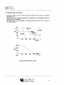
RS 422 CONFIGURATION:
Using the RS422 interface, one or more Bio Controllers (max. 10) can be connected to a
(personal) computer, using the multi-drop principle; see figure below:
When more than
one Bio Controller is connected to a computer, using the RS422 interface, the computer uses
the station number of each Bio Controller as an ID#; this is called multi-drop.
The typical characteristic is that this is always a "master"-"slave" configuration.
RS 485 CONFIGURATION:
When using the RS485 interface, the computer and Bio Controllers can be configured as a
'network'; see figure below:
maximum 32 devices
Typical characteristic of a network is that each station can become the master.
§t applikorf
DEPENDABLE INSTRUMENTS
SERIAL COMMUNICTION MANUAL
ADI 1030
SERIAL COMMUNICATION
Firmware V2.2x, March 1999
The Command-separator has 3 possible forms: the character "C", the character "A" or the
character "E".
When the command-string is send by the HOST, "C" is used to denote a COMMAND (this
can be a request for data or a command).
When the Bio Controller replies to the command, "A" is used to return the requested data or
to acknowledge the command; "E" is used to report an error.
The DATA-section holds the data to be used for the function(s). When the HOST sends data
to the Bio Controller, it uses the Data-section to transport it; when the HOST requests data
from the Bio Controller, the Data-section must be empty (in fact, an empty data-section marks
a request).
Note that when a function is an implicit command (i.e. a function that doesn't need data to
perform some action) the Data-Section is also empty.
The CHECKSUM-section is optional and holds both the Checksum-separator 7' and the
checksum itself. The checksum consists of two characters which represent a byte-value. This
byte-value is the checksum of the transmitted data.
The command-string always ends with a <CR> (carriage return), the use of a <LF> (line
feed) is optional.
$k cpotorr
DEPENDABLE INSTRUMENTS
SERIAL COMMUNICATION MANUAL
AD. 1030
SERIAL COMMUNICATION
Firmware V2.2x, March 1999
2.2 INSTRUCTION-SECTION:
The instruction-section is the section that addresses a specific function or a group/list of
functions of the Bio Controller. Therefore, this section should always be used.
The Instruction-Section starts with the Mode-Character (F, B or L) which selects the mode
to be used.
The other data in the instruction-section depends on the Mode being used, so the different
modes will be discussed now with the relevant data.
FUNCTION-MODE:
The FUNCTION-Mode is the primary-mode, used by the ADI-protocol; all other modes are
supersets of the Function-Mode.
All information that is retrieved from or send to the Bio Controller uses the Function-Code
to address a specific function.
The Function-Code is build hierarchically, formed by several base-groups.
These base-groups are: 0 - utilities
1 - input-values
2 - input-control
3 - controller output/configuration
4 - output-control
5 - output
6 - operation-control
The base-groups are divided into several sub-groups. These are discussed later in this section.
These groups and sub-groups are addressed using numbers; together, these numbers form the
Function-Code.
All numbers are separated by periods, creating the format: ¥n.m.o.p... z (e.g. F3.3.1).
The maximum number of sub-groups (or items) is not defined by the protocol itself; the ADI
1030 Bio Controller has a maximum of 6 items.
When a function-code is not available, an error will be returned:
example:
command:
reply:
<STX>¥0.5AC<CR>
(unknown function)
<m>F0.5.1E32<Ci?><Z,F> (error-32)
Note that the <STX>, <CR> and <LF> character will be omitted in the examples from now
on.
Eiappikorf
DEPENDABLE INSTRUMENTS
SERIAL COMMUNICATION MANUAL
SERIAL COMMUNICATION
ADI 1030
Firmware V2.2x, March 1999
LIST-MODE:
The LIST-mode can be used to request (not command) a predefined (programmed) LIST of
function-codes that are addressed with a corresponding List-Number.
This list of functions is programmed using the ADI-protocol.
A LIST can be programmed in the following order:
- Clear any previous items of list x,
- Program line 1 of list x,
- Program line 2 of list x,
- Program line last of list x.
Clearing an existing list: <STX>LHstNumberCO<CR>
Programming a new line: <STX>hlistNumberClineNumber/unctionCode<CR>
Example of programming lists:
Command:
Reply:
Command:
Reply:
Command:
Reply:
Command:
Reply:
Command:
Reply:
Command:
Reply:
L1C0
L1A
L1C1,O.3.2
L1A
L1C2,3.2.1.1
L1A
L1C3,3.2.2.1
L1A
L1C4,3.2.3.1
L1A
L1C5,3.2.5.1
L1A
(clear list-1 completely)
(acknowledge by ADI 1030)
(program: list-1, line-1: time)
(acknowledge by ADI 1030)
(program: list-1, line-2: controller output pHl)
(acknowledge by ADI 1030)
(program: list-1, line-3: controller output tempi)
(acknowledge by ADI 1030)
(program: list-1, line-4: controller output DO1)
(acknowledge by ADI 1030)
(program: list-1, line-5: controller output level 1)
(acknowledge by ADI 1030)
Command:
Reply:
Command:
Reply:
Command:
Reply:
Command:
Reply:
Command:
Reply:
Command:
Reply:
L2C0
L2A
L2C1,O.3.2
L2A
L2C2,1.1.1.1
L2A
L2C3,1.1.2.1
L2A
L2C2,1.1.3.1
L2A
L2C2,1.1.5.1
L2A
(clear list-2 completely)
(acknowledge by ADI 1030)
(program: list-2, line-1: time)
(acknowledge by ADI 1030)
(program: list-2, line-2: input value of pHl)
(acknowledge by ADI 1030)
(program: list-2, line-2: input value of tempi)
(acknowledge by ADI 1030)
(program: list-2, line-2: input value of DO1)
(acknowledge by ADI 1030)
(program: list-2, line-2: input value of level 1)
(acknowledge by ADI 1030)
applikorf
DEPENDABLE INSTRUMENTS
SERIAL COMMUNICTION MANUAL
ADM030
SERIAL COMMUNICATION
Firmware V2.2x, March 1999
2.3 UNIT-MODE:
The maximum length of the command string is limited (128 characters). The unit mode
however makes it possible to exceed this maximum number of characters.
When one of the ADI Instruments (working with this ADI protocol) creates a reply-string that
contains more than 128 characters, it automatically splits the string into UNITs. Only the first
unit is send:
example:
command:
L4c
(request List-4)
reply:
L4U1 aO@ .. 0@0@
(reply of first UNIT)
The host must acknowledge this first unit:
command:
L4Ulc
(acknowledge Unit-1)
reply:
L4U2a0@0@ .. 0@0@ (reply second Unit)
this process continues until the last Unit is replied by the ADI Instrument:
command:
reply:
L4U4c
L4UOaO@0@0@0@
(acknowledge Unit-4)
(reply last Unit, always Unit-0)
The last unit is always marked as Unit-0, so the receiver can see that this is the last unit. The
host does not have to acknowledge the last unit.
When the ADI Instrument decides to switch to the Unit-mode (because the reply string
exceeds 128 characters) and the host does not acknowledge this but requests another function,
error 39 (compound message error) is generated; whenever error 39 is generated, the internal
Unit-mode mechanism is put in hold until the proper reply is received.
The UNIT-mode mechanism can be reset (without generating an error) by sending (from Host
to ADI Instrument) the command FO.
The UNIT-mode can also handle the REPEAT command to request the last unit once again.
In that case the ADI Instrument simply replies the same unit again:
example:
command:
L4U3c
(acknowledge Unit-3)
reply:
L4U4a0@0@ .. 0@0@ (reply unit-4)
command:
L4U4cR
(repeat command Unit-4)
reply:
L4U4a0@0@ .. 0@0@ (reply unit-4 again)
Note:
- The ADI 1030 Bio Controller does not make use of up/down loadable user programs, so the
application of the unit-mode will not occur very often. An example where the unit mode will
be used is requesting all four display lines in a block.
appiikorf
DEPENDABLE INSTRUMENTS
SERIAL COMMUNICTION MANUAL
ADI 1030
SERIAL COMMUNICATION
Firmware V2.2x, March 1999
2.5 DATA-SECTION:
The DATA-section holds the data to be used for the function(s). When the HOST sends data
to the Bio Controller, it uses the Data-section to transport it; when the HOST requests data
from the Bio Controller, the Data-section must be empty (in fact, an empty data-section
normally marks a request).
When a function is an implicit command (i.e. a function that doesn't need data to perform
some action) the Data-Section is also empty.
When the command-separator indicates an error, the data-section contains the error-code. The
error-code is a 2-digit number representing the type of error; see the ERROR-CODES section
for a complete list and discussion of all possible errors.
The contents of the data-section can be numeric (digits) as well as alpha-numeric (characters
and digits), depending on the function. The fast-float notation is an alpha-numeric notation
of numeric-data.
The length of the data-sections is restricted by the maximum length of the command-string,
which is 128 bytes. When all sections in the command-string are used to the maximum, only
92 characters remain for the data-section; not using the module-section and not padding with
0's (e.g. F000.001.001, which is legal) leaves 100 characters to the data-section in worst-case.
The characters in the data-sections should all be readable 7-bits ASCII-characters (to be
precise, ASCII only defines 7-bits characters). Readable means that the first 32 ASCIIcharacters (which are control-characters, like <CR> or <TAB>) should not be used.
The IBM-extension on the ASCII-definition is not supported; this means that the degree
Celsius sign (tO1), which is available in the IBM-extension characterset, can not be transmitted
by the ADI-protocol. When for example the contents of the display lines are requested, all non
ASCII-characters are replaced by underscore ('_').
The number of characters returned for a numeric-value totally depends on the function that
is requested. The total number of digits (including the minus and decimal-point) is always
restricted to 8. The number of digits on the right-side of the decimal-point depends on the
function. Some functions are integer by nature (e.g. output-number), others have a fixed
number of decimals (e.g. pH-value) and some have a floating number of decimals (e.g. dose
monitor values).
However, the maximum number of decimals is restricted to 2. When the magnitude of the
numeric-value is too large to be represented using its predefined format, first the number of
decimals is diminished. If the magnitude is still too large, the digits are replaced by the
overflow notation ' » » » » ' (the number of greater-than signs is equal to the maximum
number of characters).
When the numeric-value has an underflow (e.i. too low to be represented using the maximum
number of decimals), the overflow-notation is also used.
i) appiikorf
DEPENDABLE INSTRUMENTS
13
SERIAL COMMUNICATION MANUAL
ADI 1030
SERIAL COMMUNICATION
Firmware V2.2x, March 1999
2.6 CHECKSUM-SECTION:
The CHECKSUM-section is optional and holds both the Checksum-separator V and the
checksum itself. The checksum consists of two characters which represent a byte-value. This
byte-value is the checksum of the transmitted data, starting with the <STX>-character
inclusive and ending at the Checksum-separator inclusive. The checksum is calculated by
adding all ASCII-values of the characters (e.g A = 65) discarding the carry (overflow when
the sum exceeds 255, result is the remainder of sum / 256). The checksum is transmitted using
a method like the ADI-fastfloat notation, in this case thefastbyte notation. First the low-nibble
(lowest 4-bits) of the byte-value is converted into a character on the range [0..?], second the
high-nibble is converted into a character in the range [@..O] (see Fast-Float mode for more
details).
The transmitted checksum (the checksum in the checksum-section) should be equal to the
checksum of the received characters (calculated by the receiver); if the checksum is not equal,
the Bio Controller returns error-24 (checksum error).
If the Host uses the checksum-option, the ADI 1030 Bio Controller will also return it.
example of checksum calculation:
command:
<STX>F0.1.1C/
byte-values:
sum:
checksum:
low-nibble:
high-nibble:
2 + 70 + 48 + 46 + 49 + 46 + 49 + 67 + 47
424
424 mod 256 = 168
168 mod 1 6 = 8
character = '8'
168 div 16 = 1 0
character = T
command-string:
<STX>¥0.1.1C/8 J< CR>
appiikorf
DEPENDABLE INSTRUMENTS
15
SERIAL COMMUNICATION MANUAL
SERIAL COMMUNICATION
ADI 1030
Firmware V2.2x, March 1999
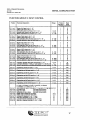
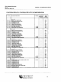
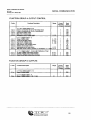
FUNCTION GROUP 2: INPUT CONTROL
F-code
Functional Description
Range
Format
float or #
of chars.
Read
Write
Command
0-20
0-20
0-150
f
f
f
f
f
R
R
R
R
R
0-150
0-150
f
f
f
f
R
R
R
R
0-500
0-500
f
f
f
f
R
R
R
R
0-100
0-100
f
f
f
f
R
R
R
R
R
R
R
R
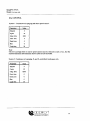
2.1.1.n.1
2.1.1.n.2
2.1.1.n.3
2.1.1.n.4
2.1.1.n.5
Slope of pH input n (n = 1 - 4)*
Offset of pH input n (n = 1 - 4)*
First buffer value for pH input n (n = 1 - 4)*
Second buffer value for pH input n (n = 1 - 4)*
Buffer temperature for pH input n (n = 1 - 4)*
2.1.2.n.1
2.1.2.n.2
2.1.2.n.3
2.1.2.n.4
Slope of temp input n (n = 1 - 4)*
Offset of temp input n (n = 1 - 4)"
First calibration value for temp input n (n = 1 - 4)*
Second calibration value for temp input n (n = 1 - 4)*
2.1.3.n.1
2.1.3.n.2
2.1.3.n.3
2.1.3.n.4
Slope of dO2 input n (n = 1 - 4)*
Offset of dO2 input n (n = 1 - 4)*
First calibration value for dO2 input n (n = 1 - 4)*
Second calibration value for dO, input n (n = 1 - 4)*
2.1.4.n.1
2.1.4.n.2
2.1.4.n.3
2.1.4.n.4
Slope of dCO2 input n (n = 1 - 4)"
Offset of dCO2 input n (n = 1 - 4)*
First calibration value for dCO2 input n (n = 1 - 4)*
Second calibration value for dCO7 input n (n = 1 - 4)*
2.1.7.n.1
2.1.7.n.2
2.1.7.n.3
2.1.7.n.4
Slope of mV/mA input n (n = 1 - 4)*
Offset of mV/mA input n (n = 1 - 4)*
First calibration value for mV/mA input n (n = 1 - 4)*
Second calibration value for mV/mA input n (n = 1 - 4)'
0-1000
0-1000
f
f
f
f
2.2.1.n.1
2.2.1.n.2
2.2.1.n.3
Correction Sample value (and command)(n = 1-4)*
0-20
Correction Method (1 = fixed, 2 = use input)(n = 1-4)* see 1.4
1,2
Value for temperature correction (temperature or input number " 0-150
f
f
f
W
RW
RW
2.3.1.n.1
Engineering unit of pH input (n = 1 -4)*
0-33
f
RW
2.3.2.n.1
Engineering unit of temp input (n = 1 - 4)*
0-33
f
RW
2.3.3.n.1
Engineering unit of dO, input (n = 1 - 4)*
0-33
f
RW
2.3.4.n.1
Engineering unit of dCO, input (n = 1 - 4)*
0-33
f
RW
2.3.5.n.1
Engineering unit of level input (n = 1 - 4)*
0-33
f
RW
2.3.6.n.1
Engineering unit of Redox input (n = 1 - 4)*
0-33
f
RW
2.3.7.n.1
Engineering unit of mV/mA input (n = 1 - 4)*
0-33
f
RW
2.4.t.n.1
2.4.t.n.2
2.4.t.n.3
2.4.t.n.4
2.4.t.n.5
2.4.t.n.6
2.4.t.n.7
2.4.t.n.8
2.4.t.n.9
2.4.t.n.1O
t = 1:pH, t = 2:Temp., t = 3:dO2> t = 4: dCO2, t = 5:Level
t = 6:Redox, t = 7:mV/mA, n = 1 - 4*
Alarm status of input (0 = no alarm, 1 = low alarm, 2 = high ala m) 0,1,2
Low alarm limit
(not valid for level input)
High alarm limit
(not valid for level input)
Hysteresis on alarm limits
(not valid for level input)
Digital output number for Low alarm
0-9
Digital output number for High alarm
0-9
Low alarm to display (0 = no, 1 = yes)
0,1
High alarm to display (0 = no, 1 = yes)
0,1
Low alarm freezes controller (0 = no, 1 = yes)
0,1
High alarm freezes controller (0 = no, 1 = yes)
0,1
f
f
f
f
f
f
f
f
f
f
R
RW
RW
RW
RW
RW
RW
RW
RW
RW
\ appiikorf
DEPENDABLE INSTRUMENTS
17
SERIAL COMMUNICATION MANUAL
SERIAL COMMUNICATION
ADI 1030
Firmware V2.2x, March 1999
FUNCTION GROUP 3: CONTROLLER OUTPUT/CONFIGURATION
F-code
Functional Description
Range
3.1.1.n.1
3.1.1.n.2
3.1.1.n.3
3.1.1.n.4
3.1.1.n.5
3.1.1.n.6
3.1.1.n.7
3.1.1.n.8
3.1.1.n.9
n = 1 - 4*
Setpoint of pH control loop
Dead zone of pH control loop
"currently not in use"
"currently not in use"
P gain of pH control loop
I interval of pH control loop
D interval of pH control loop
Bias of pH control loop
Freeze value of pH control loop
3.1.2.n.1
3.1.2.n.2
3.1.2.n.3
3.1.2.n.4
3.1.2.n.5
3.1.2.n.6
3.1.2.n.7
3.1.2.n.8
3.1.2.n.9
n = 1 - 4'
Setpoint of temp control loop
Dead zone of temp control loop
"currently not in use"
"currently not in use"
P gain of temp control loop
I interval of temp control loop
D interval of temp control loop
Bias of temp control loop
Freeze value of temp control loop
3.1.3.n.1
3.1.3.n.2
3.1.3.n.3
3.1.3.n.4
3.1.3.n.5
3.1.3.n.6
3.1.3.n.7
3.1.3.n.8
3.1.3.n.9
n = 1 - 4"
Setpoint of dO2 control loop
Dead zone of dO2 control loop
"currently not in use"
"currently not in use"
P gain of dO2 control loop
I interval of dO2 control loop
D interval of dO2 control loop
Bias of dO2 control loop
Freeze value of dO, control loop
3.1.4.n.1
3.1.4.n.2
3.1.4.n.3
3.1.4.n.4
3.1.4.n.5
3.1.4.n.6
3.1.4.n.7
3.1.4.n.8
3.1.4.n.9
n = 1 - 4*
Setpoint of dCO2 control loop
Dead zone of dCO2 control loop
"currently not in use"
"currently not in use"
P gain of dCO2 control loop
I interval of dCO2 control loop
D interval of dCO2 control loop
Bias of dCO2 control loop
Freeze value of dCO, control loop
3.1.5.n.1
3.1.5.n.2
3.1.5.n.3
3.1.5.n.4
3.1.5.n.5
3.1.5.n.6
3.1.5.n.7
3.1.5.n.8
3.1.5.n.9
n = 1 - 4*
Desired situation of level control loop (0 or 100)
"currently not in use"
"currently not in use"
"currently not in use"
"currently not in use"
Lag time of level control loop
Maximum on-time of level control loop
"currently not in use"
"currently not in use"
Siappiikorf
DEPENDABLE INSTRUMENTS
Format
Read
float or #
Write
of chars. Command
-/+400
-/+400
f
f
f
f
f
f
f
f
f
RW
RW
R
R
RW
RW
RW
RW
RW
-/+400
-/+400
f
f
f
f
f
f
f
f
f
RW
RW
R
R
RW
RW
RW
RW
RW
-/+400
-/+400
f
f
f
f
f
f
f
f
f
RW
RW
R
R
RW
RW
RW
RW
RW
-/+400
-/+400
f
f
f
f
f
f
f
f
f
RW
RW
R
R
RW
RW
RW
RW
RW
f
f
f
f
f
f
f
f
f
RW
R
R
R
R
RW
RW
R
R
0,100
19
SERIAL COMMUNICTION MANUAL
SERIAL COMMUNICATION
ADI 1030
Firmware V2.2x, March 1999
FUNCTION GROUP 4: OUTPUT CONTROL
F-code
Functional Description
Range
Format
float or #
of chars.
Read
Write
Command
f
f
f
f
f
RW
RW
RW
RW
RW
4.5.0.1
4.5.0.2
4.5.0.3
4.5.0.4
4.5.0.5
o = 1 or 2: analog output 1 or 2
Value to correspond with 0/4 mA of analog output
Value to correspond with 20 mA of analog output
Low limit of analog output
High limit of analog output
Engineering unit of analog output
4.6.0.1
4.6.0.2
4.6.0.3
4.6.0.4
4.6.0.5
4.6.0.6
4.6.0.7
4.6.0.8
o = 1-9: digital output 1-9
Value of digital output
0-100
Cycle time of digital output
0, 0.4 Low limit % of digital output
0-100
High limit % of digital output
0-100
Dose monitor value of digital output
Addition rate of dose monitor
Engineering unit of dose monitor
0-33
Map dose monitor value to recorder (0 = unmapped, 1,2 = outp ut) 0,1,2
f
f
f
f
f
f
f
f
R
RW
RW
RW
R
RW
RW
RW
4.7.0.1
4.7.0.2
4.7.0.3
o = 1-9: digital output 1-9 (only valid if defined as Timer)
On time of digital output (timer function)
Off time of digital output (timer function)
Delay time of digital output (timer function)
f
f
f
RW
RW
RW
0-33
0, 0.2 0, 0.2 0, 0.2 -
FUNCTION GROUP 5: OUTPUTS
F-code
Functional Description
Range
5.1.0
o = 1 or 2: analog output 1 or 2
Value of analog output
5.2.0
o = 1-9: digital output 1 - 9
Status of digital output (0 = off, 1 = on)
appiikorf
DEPENDABLE INSTRUMENTS
0,1
Format
Read
float or #
Write
of chars. Command
f
RW
f
RW
21
SERIAL COMMUNICATION MANUAL
SERIAL COMMUNICATION
ADI 1030
Firmware V2.2x, March 1999
4. ADDITIONAL REMARKS:
- Serial configuring of outputs is only valid when the controller is not running or not
configured at all.
- Low and high limits of outputs can only be editted when the controller is not running.
- List of commands for serial keyboard emulation:
# = Clear
> = Enter
@ = Freeze
M = Main
P — UP
B = F2
A = F1
C = F3
E = F5
D = F4
1=1
0=0
2=2
4=4
3=3
o — o
6 =6
5=5
7=7
9=9
. = . (period) - = - (minus)
Table of number codes used in operation control:
6.1.t.nC ontroller
6.2 Procejss Timer
6.3.0 Timer
6.4.0 Dos e Monitor
Data
Read
Command
Read
Command
Read
Command
Read
Command
1
Not Active
Stop
Not Active
at 0 sec.
Stop
Not Active
Stop
Undefined
Undefine
2
Active
Start
Active
Start
Active
Start
Active
Define
3
Frozen
Freeze
Interrupted
Reset
Alarm or
Controller
Define
Free
Undefine
4
Unfreeze
Reset
• The I- and D-intervals (3.1.t.n.6 and 3.1.t.n.7) must be given in seconds.
• Writing data to outputs using the functions 4.5.o.x and 4.6.o.x is only valid when these
outputs are properly configured.
• Mapping a Dose Monitor (output 1 - 9) to a recorder is only valid when the corresponding
analog output was not yet in use. Writing function 4.6.0.8 will define the analog output as a
recorder and copy the engineering unit from the dose monitor to the analog output.
• The maximum time value in the ADI 1030 display is 9999:59:59 (HHHH:MM:SS). This
gives a range in seconds of 0 - 35999999. The On, Off and Delay times have a resolution of
1 sec. The sum of On and Off time (= cycle time) may not exceed 35999999 sec.
Values become effective immediately if possible; otherwise at the beginning of the next cycle.
• In case the temperature correction method and corresponding data is done by serial
communication, the following procedure must be used:
In case a fixed correction needs to be changed in a temperature input correction: first
write the temperature input number to 2.2.1.3, next write value 2 to 2.2.1 .n.2.
In case a temperature input correction needs to be changed to a fixed correction: first
write the value 1 to 2.2.1.n.2, next write the correction temperature to 2.2.1.n.3.
applikorf
DEPENDABLE INSTRUMENTS
23
SERIAL COMMUNICATION MANUAL
ADI 1030
SERIAL COMMUNICATION
Firmware V2.2x, March 1999
5. ERROR CODES:
Whenever and error occurs in receiving or interpreting the command-string, the ADI 1030 Bio
Controller responds with an error-message. An error-message is coded by using an !E'
character at the position of the command separator:
<stx>[Ntofrom] [Fcode\Bcode\Lcode] [UunitJEcode<ci>[<\f>]
The data-section contains a number that represent an error-code. Each error (error-source) has
its own error-code. These errors are:
Communication-Line Errors (all starting with 1)
11
12
13
parity error
parity fault during the reception of the command-string; check for correct setting of
the parity (none, even, odd) on both devices (Bio Controller and host).
framing error
no stop-bit is, or not enough stopbits are, detected at the end of the character. Check
the number of stop-bits (1 or 2) and data-bits (7 or 8) on both devices.
USART overrun error
a character of the command-string is not read in time (by the Bio Controller), the next
character has overrun its predecessor; set the correct baud-rate (i.e. use a lower
baudrate) or use handshake (X-on / X-off)
Data-Errors (starting with 2)
21
22
23
24
25
syntax error
the received command-string can not be interpreted by the Bio Controller.
numerical error
the numerical data in a section is not correct, the numeric-field (i.e the section where
the number is expected) contains no numerical characters, contains a non-numerical
character, or contains too much numerical-characters.
internal buffer overflow
too many data is send to the Bio Controller in one command-string. The maximum
length of the command-string is 128 characters including the <stx> and <cr>.
checksum error
the received checksum is not correct.
checksum expected / checksum not expected
no checksum is received while expected or a checksum is received while not
expected.
< applikorf
DEPENDABLE INSTRUMENTS
25
SERIAL COMMUNICTION MANUAL
SERIAL COMMUNICATION
ADI 1030
Firmware V2.2x, March 1999
6. COMPATIBILITY WITH FORMER COMMUNICATION PROTOCOL:
An ADI 1030 Bio Controller with a previous firmware version (e.g. VI .3X) uses a different
(old) protocol. For this reason, the firmware version V2.0X also supports this old protocol,
however its application is limited.
Note:
- The format of the first request by the host after "power up" of the ADI 1030 Bio Controller
determines which protocol is selected by the ADI 1030. Switching of communication protocol
is only valid after "power off/on".
Communication with use of the "old" protocol is based on the following strings:
Data request (or command) string: Bl, B2, B3, B4, B5.
Byte
Description
B1
Start of text (ASCII 2)
CHR$(2)
B2
Bio Controller device number to be addressed
followed by command separator <,>
MA (A=1 to 99)
B3
Request or command followed by command
separator <,>
See tables on next pages
B4
Value (optional, only in case of a command)
B5
String termination
CR
Reply string: Bl, B2, B3, B4, B5
Byte
Description
B1
Start of text (ASCII 2)
CHR$(2)
B2
Bio Controller device number identification
followed by command separator <,>
MA (A=1 to 99)
B3
Request or command followed by command
separator <,>
See tables on next pages
B4
Reply
B5
String termination
CR, LF
27
DEPENDABLE INSTRUMENTS
SERIAL COMMUNICTION MANUAL
SERIAL COMMUNICATION
ADI 1030
Firmware V2.2x, March 1999
COMMANDS FOR SERIAL COMMUNICATION (old protocol):
On these pages, the commands (function codes, composed like FXYZ) that can be used in
serial communication (old protocol), are listed. The page number indicates at which page in
the corresponding user manual the function is explained.
The code R means "read only", the code R/W means "read and write".
GENERAL GROUP:
FX
Sensor input value (X = 1 .. 4), p 2-3
F5
Uref value (service menu), p 2-25
F6
Ubat value (service menu), p 2-25
F7
Firmware version (service menu), p 2-25
F62
Device number, p 2-24
R
R
R
R
R
GROUP 1: P.I.D. parameters (Y = 1 .. 4, controller number)
F1Y0 Setpoint, p2-15
R/W
F1Y1 P-gain,p2-15
R/W
F1Y2 Integral time, p 2-15
R/W
F1Y3 Derivative time ,p2-16
R/W
F1Y4 Dead zone, p 2-16
R/W
F1Y5 Process time, p 2-22
R/W
F1Y6 Range low, p 2-17
R/W
F1Y7 Range high, p 2-17
R/W
F1Y8 Output #,p 2-18
R/W
F1Y9 Bias value, p 2-16
R/W
GROUP 2a: Output status (Y = 1 .. 9, solid state number)
F2Y
Solid state output number (0 = off, 1 = on), p 2-12 R
GROUP 2b:
F2Y1
F2Y2
F2Y3
F2Y4
F2Y5
F2Y6
Calibration (Y = 1 .. 4, input number)
Value of first buffer, p 2-8
Value of second buffer, p 2-8
Obtained slope, p 2-8
Obtained offset ,p2-8
Buffer temperature, p 2-8
Temp, correction (pH calib. only), p 2-11
1 = fixed temp, correction
2 = automatic temp, correction
F2Y7 Data for F2Y6:
temperature for fixed correction or
number of temp, amplifier (auto corr.)
1 appiikorf
DEPENDABLE INSTRUMENTS
R
R
R
R
R
R
R
29
SERIAL COMMUNICTION MANUAL
SERIAL COMMUNICATION
ADI 1030
Firmware V2.2x, March 1999
7. IDENTICAL FUNCTIONS IN OLD AND NEW PROTOCOL:
The firmware V2.0 does not use the following parameters any longer:
Process Time (F1Y5),
Range Low (Fl Y6) and
Range High (F1Y7).
In the firmware V2.0, the Freeze values are defined per control loop in stead of per output
(F5Y4 and F7Y5).
As a result, these functions can not be found in the function list of the new Applikon
communication protocol.
In the list below, the corresponding functions can be found; if a direct replacement does not
exist due to changes in the firmware, the alternative is given between braces.
Old protocol
Fx
F5
F6
F7
F62
F1 Yx
F2Y
F2Y1
F2Y2
F2Y3
F2Y4
F2Y5
F2Y6
F2Y7
F3Y
F3Y0
F3Y1
F3Y2
F4Y0
F4Y1
F4Y2
F4Y3
F4Y4
F5Y0
F5Y1
F5Y2
F5Y3
F5Y4
Description
Sensor input value (x = 1 - 4)
Uref value
Ubat value
Firmware version
Device number
Parameter list (x = 0 - 9)
Digital output status
First buffer value
Second buffer value
Obtained slope
Obtained offset
Buffer temperature
Temperature correction
Data for F2Y6
Analog output value
Dosed value
Addition rate of dose monitor
To output 10/11 (analog 1/2)
Value to output 10/11 (analog 1/2)
Low alarm limit
High alarm limit
Low alarm output
High alarm output
Low limit of analog output
High limit of analog output
Engineering unit
Suffix code
Freeze value
New protocol
1.1 .t.n
0.1.1
0.1.2
0.2.2
0.2.3
3.1 .t.n.y
5.2.0
2.1 .t.n.3
2.1 .t.n.4
2.1.t.n.l
2.1 .t.n.2
2.1.t.n.5
2.2.t.n.2
2.2.t.n.3
5.1.o
4.6.O.5
4.6.0.6
4.6.O.8
2.5.t.n
2.4.t.n.2
2.4.t.n.3
2.4.t.n.5
2.4.t.n.6
4.5.0.3
4.5.0.4
4.5.0.2
4.5.o.5
(3.1 .t.n.9)
appiikorf
DEPENDABLE INSTRUMENTS
31
PID CONTROL MANUAL
ADI 1030
Firmware V2.2x, March 1999
BIO CONTROLLER
AD11030
PID CONTROL MANUAL
applikorf
DEPENDABLE INSTRUMENTS
PID CONTROL MANUAL
ADI 1030
Firmware V2.2x, March 1999
TABLE OF CONTENTS
Chapter
Description
Page
Introduction
1
1.
Controller Variables
2
2.
Controller Tuning Parameters
3
3.
Actuator Variables
7
4.
Actuator Parameters
7
5.
Types of Control
8
6.
Parameters and Actuators
10
7.
Optimizing Control Parameters
14
appiikorf
DEPENDABLE INSTRUMENTS
PID CONTROL MANUAL
ADI 1030
Firmware V2.2x, March 1999
PID CONTROL MANUAL
INTRODUCTION
This manual deals with practice and theory of P.I.D. control with the ADI 1030 Biocontroller; it is an addition to the User and Operator manual.
In this manual, controller variables and controller parameters are defined and the way of
optimizing the settings is explained.
Abbreviations, used in this manual, in alphabetical order:
AO
B
CO
D
DZ
HL
I
LL
P
PV
SP
- Actuator Output
- Bias
- Controller Output
- Derivative time
- Dead Zone
- High Limit
- Integral time
- Low Limit
- Proportional gain
- Process Value
- SetPoint
appikorf
DEPENDABLE INSTRUMENTS
PID CONTROL MANUAL
ADI 1030
Firmware V2.2x, March 1999
2. CONTROLLER-TUNING PARAMETERS
2.1 PROPORTIONAL GAIN: P (% pereng. unit)
Proportional gain is the parameter for proportional control. The controller action due to
proportional control is relative to the deviation from setpoint. The proportional gain is defined
as the change in controller output per engineering unit. The equation for proportional control
is:
C0p=P*(SP-PV)
CO (%)
A 100
32
T(°C)
•100-
HEATING BLANKET
OUTPUT 1
COLD WATER VALVE +
HEATEXCHANGER
OUTPUT 2
Temperature control with two actuators.
This paragraph is continued on the next page.
appiikorf
DEPENDABLE INSTRUMENTS
PID CONTROL MANUAL
ADI 1030
Firmware V2.2x, March 1999
2.3 DERIVATIVE TIME: D (time units)
Derivative time is the parameter for derivative control. Derivative control is used to
compensate for very fast changes of a process value. The mathematical expression for
derivative control is:
dt
Due to the fact that biotechnological processes are relatively stable and slow, this derivative
part of P.I.D. control is normally not in use in these kind of applications.
2.4 BIAS: B (%)
The bias can be used to compensate for a constant offset from setpoint and is defined as the
controller action at setpoint in the absence of integral and derivative action. Bias is added to
the controller output, which results in:
CO=B+COp+COi+COd
CO(%)
100
BIAS = 0
BIAS =20
20
0
32
T("C)
•100-
Bias in temperature control
If the integral part of the controller action is constant, it can be replaced by a bias value; as
a result, the controller will reach the setpoint more quickly, since no history is required to
reach the optimum value.
appiikorf
DEPENDABLE INSTRUMENTS
PID CONTROL MANUAL
ADI 1030
Firmware V2.2x, March 1999
3. ACTUATOR VARIABLES
3.1 ACTUATOR OUTPUT: AO (%)
The actuator output relates to the actuator action. The actuator output can vary in the range
from 0% to 100%.
In case of the digital outputs 1 through 9, the actuator output % relates to the on-time of the
actuator (% of the cycle time).
In case of the analog outputs 10 and 11, the actuator output % relates to "force" of the
actuator.
4. ACTUATOR PARAMETERS
4.1 LOW/HIGH LIMIT: LL/HL (%)
The low limit is the minimum output activation. The high limit is the maximum output
activation. These limits are used to assign the minimum Controller Output to the Low Limit
value and the maximum Controller Output to the High Limit value.
An example of this application is using a stirrer speed controller in dO2 control; the Low
Limit can be set to 350 rpm, the High Limit can be set to 650 rpm. Full control range is now
350 rpm to 650 rpm.
4.2 CYCLE TIME (time units)
The cycle time is only relevant for digital outputs and defines the control interval (duty cycle)
of a digital output. Furthermore, the proportional, integral and derivative controller action is
updated after a time interval of one cycle time.
appikorf
DEPENDABLE INSTRUMENTS
PID CONTROL MANUAL
ADI 1030
Firmware V2.2x, March 1999
5.2 SEQUENTIAL CONTROL
Sequential control is used to control a process variable with more than one actuators
(maximum = 4).
The actuators will be activated sequentially as configured in the configuration menu (see
chapter 5 in the User Manual).
The figures below show an example of sequential control (both AO and CO versus %
Dissolved Oxygen).
100.
,MFC air
75-
N9valve
AO
50-
^Stirrer
Speed
O.valve
VT
250
20
30
40
50
DO(%)
300_
200-
CO
1004
0
-100
To
Jo Jo
Sequential dissolved oxygen control.
appiikorf
DEPENDABLE INSTRUMENTS
PID CONTROL MANUAL
ADI 1030
Firmware V2.2x, March 1999
infrared lamp
hot finger
D
D
MC
MC
output
D
A
application
exothermic culture
exothermic culture
Actuators for cooling
cold water valve (+ heat exchanger)
cryostat.(+ heat exchanger)
Heat exchangers
application
CC
MC
MC
MC
jacket
finger
baffles
draft tube
6.2 pH CONTROL
pH has to be controlled within a narrow range. Therefore, a P-control with a high P-value is
required. To prevent that salt production will occur around setpoint (due to excessive addition
of acid and base), a dead zone is being used; therefore both integral and derivative time are
0.
Sensor
A combined pH-glass electrode is used as a sensor; this sensor is normally calibrated with two
pH buffers.
Features
Calibration of the pH electrode is normally executed before sterilizing the reactor.
Acid/Base Pump
CO/NHS Valve
Setpoint
D
Value
Controller
Output
Config.
appiikorf
DEPENDABLE INSTRUMENTS
Mass Flow Contr.
COJNH,
11
PID CONTROL MANUAL
ADI 1030
Firmware V2.2x, March 1999
Actuators for oxygen addition
stirrer speed controller
air solenoid valve
air mass flow controller
oxygen solenoid valve
oxygen mass flow controller
output
A
D
A
D
A
application
CC/MC
CC/MC
CC/MC
CC/MC
CC/MC
output
D
A
application
CC/MC
CC/MC
Actuators for oxygen dissipation
nitrogen solenoid valve
nitrogen mass flow controller
Aeration
application
MC
CC
CC
CC
CC
sparging
sparging with filter
head space (overlay)
spin filter
silicon tubing
6.4 LEVEL CONTROL
Sensor
A level detector is used as a sensor; this sensor will or will not detect a closed circuit.
Actuator for level control
pump for anti-foam reagent
output
D
appiikorf
DEPENDABLE INSTRUMENTS
application
MC
13
PID CONTROL MANUAL
AD! 1030
Firmware V2.2x, March 1999
7.3 EXAMPLES
When the Bio Controller is operated for the first time, setting the PID parameters might be
a bit complicated; therefore some examples are given below as a rule of thumb for different
applications (temperature, pH, and dO2).
TEMPERATURE CONTROL
Direct heating (heating blanket, hot finger or jacket) and cooling (cold finger or jacket).
Parameter
Value
Setpoint
X
P-gain
20
Integr. time
4500
Deriv. time
0
Dead zone
0
Bias
0
Cycle time
30
pH CONTROL
System 1: Pump for acid and pump for alkali.
Parameter
Value
Setpoint
X
P-gain
50
Integr. time
0
Deriv. time
0
Dead zone
0.05
Bias
0
Cycle time
30
appikorf
DEPENDABLE INSTRUMENTS
15
PID CONTROL MANUAL
ADI 1030
Firmware V2.2x, March 1999
CONTROL
System 1: Continuous air sparging and stirrer speed control.
Parameter
Value
Setpoint
X
P-gain
10
Integr. time
3000
Deriv. time
0
Dead zone
0
Bias
0
Cycle time
30
Note:
• The low and high limit for stirrer speed control must be selected in such a way, that the
required minimum and maximum stirrer speed are not exceeded.
System 2: Continuous air sparging, N2 and O2 controlled, head-space only.
Parameter
Value
Setpoint
X
P-gain
20
Integr. time
6000
Deriv. time
0
Dead zone
0
Bias
0
Cycle time
30
appiikorf
DEPENDABLE INSTRUMENTS
17
Braak-ter, Dennis
From:
Sent:
To:
Cc:
Subject:
Rob Claeijs [[email protected]]
Friday, May 07, 2004 10:07 AM
Braak-ter, Dennis
Service Bio; Frank van den Hoogen
AD11030
ADI1030_jumpers for
analog out...
Geachte heer Ter Braak,
Bijgevoegd vindt u een tekening van het processord bord van de ADI1030.
In de linker bovenhoek ziet u 2 x 2jumpers.
Voor uitgang 1 worden jumpers X3 en X5 gebruikt.
Voor uitgang 2 worden jumpers X7 en X9 gebruikt.
Op de tekening staat rechts boven hoe de jumpers moeten staan aan de hand van welk
uitgangssignaal u nodig heeft. De uitgang zal nu op 4-20mA staan, dit moet gewijzigd
worden naar 0-20mA.
With best regards,
Applikon Biotechnology
Department Technical Service
Rob Claeijs
+++++++++++telephone: +31 10 2983404
faxcimile: +31 10 4379648
email: [email protected]
CHANNEL 1: X3 & X5
CHANNEL 2: X7 & X9
JO-2OmA
X19
4-20mA
0(4)-20mA OUTPU
Jumper settings
X24
ISOL.GROUND
X14
SENSOR CONTROL BOARD
5VREF
AGND
X2
SERIAL
X11
SOLID STATES
X16
0 DISABLE WATCHDOG (SOFTWARE)
X23
X23
GROUND
OGND
1
X20
WATCHDOG
D
X20
X18
X28
RST6.5
5n
LJ
Rtune
X17
X29
-15V
X17
+15V
POWER SUPPLY
GND
X12
X13
BACKLIGHT
X21
-15V
+15V
+5V
BACKLIGHT
X12
DISPLAY
EARTH
OUT2
Q1X13
R1
R2
R5
R6
R13
R39
X16
X18
X21
OEARTH
X1KEYBOARD
d NGa X14 TYPE CHANGED.
CHANNEL 1 - OFFSET
CHANNEL 1 - SPAN
CHANNEL 2 - OFFSET
CHANNEL 2 - SPAN
5Vref - SPAN
DISPLAY - VIEW ANGLE
DISABLE WATCHDOG (SOFTWARE)
Rtune
29 Jan. 2002 HMa
16 jun. 1995 16 jun. 95 RCI
RHu
REV. DRAWN
PROJECTION : DRAWING NAME
=
=
=
=
=
=
=
=
REVISION DATE
REVISION
CONTROLLER BOARD
PART NBR.:
toappiikorf
DESIGNED
^ ^ ^ ^ B I O T E C H N O L O G Y
V1LE040012
1
20 mar. 1991
DRAWING
S1030-2d. 04.001
RHu
£3P.O. BOX 149
3100 AC SCHIEDAM
APPR.:
SHEET:
attached drawings
iLaPiEnTaS
© 2003 Applikon Dependable Instruments B.V.
No part of this drawing may be copied or reproduced in any form or by any means or transferred
to any third party without the prior written consent of Applikon Dependable Instruments B.V.
A.D.I. B.V.
CHECKED
HOLLAND
@ (31)10-2983555
DIMENSIONS
ARE IN mm
EAX (31)10-4379648
SIZE
A3