1
GEBRUIKSAANWIJZING
ADI 1035 Bio Console
Versie 3, oktober 1996
BIO CONSOLE
ADI 1035
GEBRUIKSAANWIJZING
1. Basis Bio Console
2. Gastoevoer
3. Temperatuurregeling
4. Roersnelheidsregel ing
5. Niveauregeling
6. Pompen
7. Schakelaarstanden
8. Tekeningen
appiiKorf
DEPENDABLE INSTRUMENTS
V1UJNL1013
D e c l a r a t i o n of
Nederlands Meetinstituut
Product description
Manufacturer
Brand
Type
Serial number(s)
Number of tested products
Conformity
Bio Console
Applikon Dependable Instruments B.V.
Applikon
AD11035
P19196/2
1
This declaration of conformity is issued based on testing a series produced sample of the
above-mentioned product(s) in conformity with the following standard:
Standard
Issue
EN 50081-1 (1992),
EN 50082-1 (1992), EN 50082-2 (1995).
EN 61000-3-2 (1995), EN 61000-3-3 (1995),
EN 50082-2 (1995): Table A.4
Positive
The measuring results are available at NMi with project number: 10047984
This declaration of conformity is granted under project number: 10047984
Name applicant
Address applicant
Postal code/City
Country
Applikon Dependable Instruments B.V.
De Brauwweg 13
3125 AE SCHIEDAM
The Netherlands
Niekerk
T.E.T.
NMiC
Nederlands Meetinstituut
P.O. Box 15
9822 ZG Nlekerk (NL)
Smldshornerweg 18
9822 TL Niekerk
Telephone +31 594 505005
Telefax +31 594 504804
Nederlands Meetinstituut N.V. (Registered at the
Chamber of Commerce Delft number 28701}
Offices:
Delft, Bergum, Utrecht, Dordrecht, Helmond,
Niekerk
Subsidiary companies:
NMi Van Swinden Laboratorium B.V. (28703)
NMi Ukwezen B.V. (28700)
NMi Certin B.V. (33418)
NMi Test- en Adviescentrum (TAQ B.V. (28702)
This declaration is issued under the provision that
Nederlands Meetinstituut N.V. nor its subsidiary companies
accept any liability.
Reproduction of the complete certificate is allowed.
Parts of the certificate may only be reproduced after
written
permission.
GEBRUIKSMNWIJZING
SYMBOLEN
ADI 1035 Bio Console
Versie 3, oktober 1996
SYMBOLEN
De volgende symbolen worden gebruikt op de instrumentatie en in de documentatie:
Let op; kijk in de gebruiksaanwijzing.
Let op; kans op electrische schok.
I
Belangrijke opmerking; lees de instructies zorgvuldig.
Applikon Dependable Instruments
3125 AE Schiedam
Tel.: 010-4621855
<a
appiikor?
DEPENDABLE INSTRUMENTS
De Brauwweg 13
Nederland
Fax.: 010-4379648
GEBRUIKSMNWIJZING
BASIS BIO CONSOLE
ADI 1035 Bio Console
Versie 3, oktober 1996
HOOFDSTUK 1
BASIS BIO CONSOLE
1.1 INLEIDING:
De ADI 1035 Bio Console is een aandrijvings-console voor gebruik in combinatie met
een ADI 1030 Bio Controller.
Het ondersteunt de regeling van gassen (met rotameters), regelingen van roersnelheid,
niveau, temperatuur (met heet en koud water of met een verwarmingsmantel) en het
toevoegen van vloeistoffen met pompen. Tevens wordt de koelwatervoorziening voor
de koeler in het reactordeksel ondersteund.
Door een zeer compact ontwerp stelt de ADI 1035 Bio Console u in staat om een "bioproces" te voeren op een minimale tafelruimte (de ADI 1030 Shelf-Top Bio Controller
past precies bovenop de ADI 1035 Bio Console).
Let op:
De ADI 1035 Bio Console mag uitsluitend worden
gebruikt als een aandrijvings-console voor regelaars bij
een biotechnologisch proces!
Op de volgende pagina's ziet u voor- en achteraanzicht van de ADI 1035 Bio Console
en staan er instructies vermeld ten aanzien van de installatie en aansluitingen.
<8
DEPENDABLE INSTRUMENTS
1-1
GEBRUIKSAANWIJZING
BASIS BIO CONSOLE
ADI 1035 Bio Console
Versie 3, oktober 1996
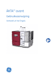
1.2 VOORAANZICHT:
B
oooo
f
D
E
oooo
IB22X2?
„»,
Bh Console ADI 1035
o
o
©
o
•:6;
G
-7-®
©
©
©
H
©
I
©
©
®
A = Plaats voor gastoevoervoorziening
C = Voedingsgedeelte
E = Niveauregeling
G = Plaats voor pomp met instelbare snelheid
I = Reactor-aansluitingen
B = Plaats voor gasselectieblok
D = Roersnelheidsregeling
F = Temperatuurregeling
H = Koeler-aansluitingen
J = Pompplaats met vaste snelh.
appiikon
($>
DEPENDABLE INSTRUMENT'S
1-2
GEBRUIKSAANW1JZING
BASIS BIO CONSOLE
ADI 1035 Bio Console
Versie 3, oktober 1996
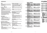
1.3 ACHTERAANZICHT:
B
A
H
A
©
©
©
D
E
F
© ©
G
TZT
A = Aansluiting voor afstandsbediening
C = Gas-aansluitingen
E = Ontluchting
G = Netkabel
I = Roersnelheidsregeling conn.
B = Voeding voor de ADI 1030
D = Water-aansluiting
F = Afvoer
H = Mass-flow-control conn.
N.B.:
D Mass Flow Control aansluitingen MFCl tot en met MFC4 (H) zijn voor toekomstig
gebruik.
Let op: De geschakelde voeding "B" is bedoeld voor de
voeding van de ADI 1030 Bio Controller. In het geval dat
deze aansluiting wordt gebruikt voor de voeding van
andere instrumentatie, is de maximale totale belasting
(beide aansluitingen) 250 W.
DEPENDABLE INSTRUMENTS
1-3
GEBRUIKSMNWIJZING
BASIS BIO CONSOLE
ADI 1035 Bio Console
Versie 3, oktober 1996
1.4 INSTALLATIE:
NETVOEDING:
De ADI 1035 Bio Console is inzetbaar in het gehele netvoedingsbereik van 110 tot
240V- (wel moet het apparaat ingesteld zijn voor de juiste spanning):
Z310351010
: Bio Console ADI 1035 110 - 240 Vac.
Controleer het gekozen voltage (zie de gele voltage-sticker naast de netvoedingskabel);
indien het gekozen voltage niet juist is, waarschuw dan uw service-dienst.
LET OP! KANS OP ELEKTRISCHE SCHOK!
Sluit de netvoedingskabel als volgt op het lichtnet aan:
- bruin
= fase,
- blauw
= nul,
- groen/geel
= aarde.
Voedingsgedeelte van de ADI 1035
A = Hoofdvoedingszekeringen
B = Aan/uit-schakelaar
MAIN POVER FUSES
C = Aan/uit indicator
D = Centrale alarm indicator
ZEKERINGSWAARDE:
220 - 240 V ~ :
T 8A,
110-120 V ~ :
T 16A.
De toegepaste zekeringen moeten voldoen aan IEC 127!
De ADI 1035 Bio Console kan nu worden ingeschakeld met de "Power On/Off"
schakelaar.
De "Alarm" LED kan worden gebruikt als algemene alarm indicatie voor sensor-waarden
(alarmen op de ADI 1030 moeten worden toegewezen aan uitgang 3; niveau-detectieschakeling moet "aan" zijn (zie hoofdstuk 7: schakelaarstanden)).
toapplikorf
^
•
^
DEPENDABLE INSTRUMENTS
1-4
GEBRUIKSAANWIJZING
ADI 1035 Bio Console
BASIS BIO CONSOLE
Versie 3. oktober 1996
GASTOEVOER:
Indien een of meerdere rotameters zijn geplaatst, dient de overeenkomstige gastoevoer
te worden aangesloten op de daarvoor bestemde schotkoppeling aan de linkerzijde van
de ADI 1035 Bio Console; zie hoofdstuk 2: Gastoevoer.
WATERTOEVOER:
Indien het waterbad, de koudwaterklep of de koeler toegepast worden, dient kraanwater
met een gereduceerde druk (30-50 kPa, 0.3-0.5 bar, 4-7 psi) aangesloten te worden aan
de linker zijkant van de ADI 1035 Bio Console; zie hoofdstuk 3: Temperatuurregeling.
Centraal in het pompgedeelte zit een naaldventiel waarmee de koelwaterstroom naar de koeler op het reactordeksel geregeld kan worden. Daaronder
zitten twee snelkoppelingen voor slangaansluitingen van en naar de koeler;
de koppeling naar de koeler bevat een terugslagklep waardoor de koeler
niet leegloopt wanneer deze aansluiting wordt losgemaakt.
Onder de aansluitingen voor de koeler zitten twee wateraansluitingen voor de
reactormantel (van en naar de mantel); ook hier zit in de koppeling naar de
reactor een terugslagklep waardoor de snelkoppeling losgemaakt kan worden
zonder dat de reactormantel leegloopt.
<Sappiikorf
DEPENDABLE INSTRUMENTS
GEBRUIKSMNWUZING
ADI 1035 Bio console
BASIS BIO C O N S O L E
Versie 3, oktober 1996
AANSLUITING VAN DE ADI 1035 AAN DE ADI 1030 CONTROLLER:
Wanneer de ADI 1030 Bio Controller wordt gebruikt in combinatie met de ADI 1035
Bio Console, dan MOET de ADI 1030 worden gevoed vanuit de ADI 1035; hierdoor
kan het gehele systeem afgeschakeld worden door de aan/uit-schakelaar van de ADI
1035. De volgende kabels zijn beschikbaar:
Z510303200 Netvoedingskabel voor het processordeel van de ADI 1030,
Z510303210 Netvoedingskabel voor de uitgangsmodule van de ADI 1030,
Z510303220 Regelkabel (regelingssignaal vanuit de ADI 1030 naar de ADI 1035).
LET OP! INDIEN DE PROCESREGELAAR (B1JVOORBEELD DE ADI 1030) NIET GEVOED WORDT
VANUIT DE ADI 1035, MOET DE VOEDING VANUIT
DE REGELAAR AAN DE ADI 1035 WORDEN
AANGEBODEN. KIJK IN HOOFDSTUK 7.2 VOOR
INSTRUCTIES
T.A.V.
AANSLUITING
EN
SCHAKELAAR-STAND!
De voedingskabels passen in de stekkerbussen aan de achterkant van de ADI 1035.
De status van de ADI 1035 aandrijvers wordt bepaald door de uitgangssignalen van de
ADI 1030 Bio Controller; de regelkabel moet worden gebruikt voor de aansluiting
tussen de uitgangs-module van de ADI 1030 en de aansluiting voor afstandsbediening
op de ADI 1035 (achterzijde).
De regelkabel moet op de volgende manier op de ADI 1030 Bio Controller worden
aangesloten (zie tabel op de volgende pagina):
LET OP! KANS OP ELEKTRISCHE SCHOK! SCHAKEL
DE VOEDING VAN DE ADI 1035 /1030 COMBINATIE
AF ALVORENS ENIGE AANSLUITING TE MAKEN!
appiikorrf
DEPENDABLE INSTRUMENTS
1-6
GEBRUIKSMNWIJZING
BASIS BIO CONSOLE
ADI 1035 Bio Console
Versie 3, oktober 1996
ADI 1030 Uitgangsnr.
ADI 1030 Klem
Draadkleur
ADI 1035 Aandrijver
Uitgang 1
X1-1
WH (wit)
Pomp 1
Uitgang 2
X1-4
BR (bruin)
Pomp 2
Uitgang 3
X1-7
GN (groen)
Pomp 3 of Alarm
Uitgang 4
X1-10
YE (geel)
Rotameterklep 1
Uitgang 5
X1-13
GR (grijs)
Rotameterklep 2
Uitgang 6
X1-1B
PK (paars)
Rotameterklep 3
Uitgang 7
X1-19
BL (blauw)
Rotameterklep 4
Uitgang 8
XI-22
RD (rood)
Verwarming
Uitgang 9
X1-25
BK (zwart)
Koeling
N.B.:
Uitgang 3 van de ADI 1030 Bio Controller kan worden gebruikt om pomp 3 van de
ADI 1035 te regelen (in dit geval mag er geen niveau-regeling geplaatst zijn in de ADI
1035) of als centrale alarm-indicator (LED) in het voedingsgedeelte van de ADI 1035
(wanneer er wel een niveau-regeling geplaatst is in de ADI 1035). Zie ook hoofdstuk
5 (niveau-regeling) en hoofdstuk 7 (schakelaarstanden).
EXTERNE AANSLUITINGEN:
Gastoevoer-schotkoppelingen:
slang: ID 4 mm
max. druk: 200 kPa (2 bar, 29 psi)
Watertoevoer:
slang: ID 6 mm
max. druk: 50 kPa (0.5 bar, 7 psi)
min. druk: 30 kPa (0.3 bar, 4 psi)
Koeleraansluitingen:
slang: ID 6 mm
Reactormantelaansluitingen:
slang: ID 6 mm
<S
DEPENDABLE INSTRUMENTS
1-7
GEBRUIKSMNWIJZING
ADI 1035 Bio Console
BASIS BIO CONSOLE
Versie 3, oktober 1996
OMGEVINGSCONDITIES:
De ADI 1035 Bio Console kan worden gebruikt op lokaties met de volgende
omgevingscondities:
-
Gebruik binnenshuis,
Hoogte: tot 2000 meter boven zeeniveau,
Omgevingstemperatuur: 4°C - 45°C,
Maximum relatieve vochtigheid: 80% voor temperaturen tot 31°C, lineair afinemend
tot 50% bij 45°C,
- Voedingsspanning: 115/230 Vac (+15%/-20%), 50/60 Hz,
- Transciente overvoltages volgens INSTALLATIE CATEGORIE II,
- VERVUILINGSGRAAD 2 volgens IEC 664.
I I
DEPENDABLE INSTRUMENTS
1-8
GEBRUIKSMNW1JZING
GASTOEVOER
ADI 1035 Bio Console
Versie 3, oktober 1996
HOOFDSTUK 2
GASTOEVOER
2.1 HET GASTOEVOERGEDEELTE:
Het ADI 1035 Gastoevoergedeelte ondersteund de toepassing van vier rotameters en een
gasselectieblok:
A = Gasselectiekleppen
Het optioneie gasselectieblok bevat vier gasselectiekleppen. Met deze kleppen wordt het
type gastoevoer ("sparging" of "overlay") gekozen.
N.B.:
- De bovenste gasinlaatkoppeling komt overeen met de linker rotameter en de bovenste
klep van het gasselektieblok.
Ordernummer van het gasselektieblok:
Ordernummer van een gasuitlaatkoppeling:
Op de volgende pagina staan de rotameters vermeld.
Z311302020
Z311302060
(gapplikorf
^
•
^
DEPENDABLE INSTRUMENTS
2-1
GEBRUIKSAANW1JZING
GASTOEVOER
ADI 1035 Bio Console
Versie 3, oktober 1996
Beschikbare rotameters:
Z3RM000005 Rotameter
Z3RM000010 Rotameter
Z3RM000020 Rotameter
Z3RM000030 Rotameter
Z3RM000040 Rotameter
Z3RM000050 Rotameter
Z3RM000060 Rotameter
Z3RM000070 Rotameter
Z3RMOOOO8O Rotameter
assembly
assembly
assembly
assembly
assembly
assembly
assembly
assembly
assembly
2.5 - 25 ml/min,
5 . 0 - 5 0 ml/min,
9.0 - 90 ml/min,
27 - 270 ml/min,
50 - 500 ml/min,
0.1-1.0 1/min,
0.5 - 5.0 1/min,
1.0 - 10 1/min,
2.3 -23 1/min.
Rotameters kunnen worden toegepast met of zonder klep:
A = Rotameter
B
A -
-
B = Elleboog
C
I
C = Terugslagklep
D = Bevestigingsplaat
E = Gas-in
F = Gas naar reactor
Rotameter
A + C = Inschroefkoppeling
-A
B
B = Slang
D = "Solenoid"-klep
-C
D
E = Montagemateriaal
G = Gas-in
F = Gas naar reactor
Rotameter met klep-module
<8
i i
DEPENDABLE INSTRUMENTS
2-2
GEBRUIKSAANWIJZING
GASTOEVOER
ADI 1035 Bio Console
Versie 3, oktober 1996
De klep-raodule is leverbaar in twee verschillende versies:
Z311302040 Valve Module for Rotameter Ass., 220 - 240 Vac,
Z311302045 Valve Module for Rotameter Ass., 110 - 120 Vac.
LET OP:
INDIEN ZUURSTOF WORDT TOEGEPAST ALS EEN
VAN
DE GASSEN, DAN
DIENEN
VOOR
INSCHAKELING
VAN DE NETSPANNING
DE
KOPPELINGEN EN SLANGEN OP LEKKEN TE
WORDEN GETEST!
N.b.:
- De rotameterkleppen kunnen worden geschakeld door de digitale uitgangen 4 t/m 7 van
de ADI 1030 Bio Controler; zie hoofdstuk 1.4 van deze gebruiksaanwijzing: Installatie.
I I
DEPENDABLE INSTRUMENTS
2-3
GEBRUIKSAANW1JZING
TEMPERATUURREGELING
ADI 1035 Bio Console
Versie 3, oktober 1996
HOOFDSTUK 3
TEMPERATUURREGELING
3.1 TEMPERATUURREGELINGSGEDEELTE:
A = Netvoedings-indicatie
B = Max. temperatuur-indicatie
C = Koeling-indicatie
D = Verwarmings-indicatie
E = Stopcontact voor verwarming
F = Voedingszekering
G = Max. temperatuurs-instelling
H = Aan / uit / vul-schakelaar
ZEKERINGSWAARDE:
220- 240 V~:
T 3.15A,
110- 120 V~:
T 6.3A.
De toegepaste zekeringen moeten voldoen aan IEC 127!
Het temperatuurregelingsgedeelte verzorgt verwarmen en koelen door middel van
verschillende principes:
In de Basis Lay-Out is het aansturingssignaal voor verwarmen (uitgang 8 van de ADI
1030) doorgeschakeld naar het stopcontact in het temperatuurregelingsgedeelte. Hierop
kan een verwarmingsmantel worden aangesloten (temperatuurregeling met slechts een
aansturing).
LET OP! KANS OP ELEKTRISCHE SCHOK. ZODRA
AANSTURING WORDT INGESCHAKELD, WORDT DE
NETSPANNING DIRECT DOORGESCHAKELD NAAR
HET STOPCONTACT!
MAXIMAAL VERMOGEN = 400 W.
DEPENDABLE INSTRUMENTS
3-1
GEBRUIKSAANWIJZING
ADI 1035 Bio console
TEMPERATUURREGELING
Versie 3, oktober 1996
N.B.:
- In dit geval worden de indicaties voor de maximum temperatuur van het waterbad en
het koelen niet gebruikt.
- Met de aan/uit-schakelaar in de middelste (Vul) stand is de temperatuurregeling
operationeel.
Met een extra koudwaterklep in de ADI 1035 kan een dubbele temperatuurregeling tot
stand worden gebracht (verwarmen en koelen). Het aandrijvingssignaal voor koelen
(uitgang 9 van de ADI 1030) wordt doorgeschakeld naar deze koudwaterklep.
N.B.:
- In dit geval is de indicatie voor de maximum temperatuur van het waterbad niet in
gebruik.
- Met de aan/uit-schakelaar in de middelste (Vul) stand is de temperatuurregeling
operationeel.
Een andere manier van dubbele temperatuurregeling is de toepassing de waterbadmodule voor de ADI 1035. Op deze manier wordt de temperatuur geregeld door heet
of koud water rond te pompen.
N.B.:
- In dit geval is het stopcontact voorop niet in gebruik.
In geval het waterbad of de koudwaterklep wordt toegepast of koud water nodig is voor
de koeler op het reactordeksel, dient leidingwater met gereduceerde druk te worden
aangesloten (bovenste koperen koppeling aan de linkerzijde van de ADI 1035);
inlaatdruk: 30 - 50 kPa (0.3 - 0.5 bar, 4 - 7 psi). Een waterdruk-reduceerventiel is
leverbaar.
De onderste koperen koppeling wordt gebruikt om water af te voeren, de middelste
koppeling is voor de ontluchting (lucht uit het circulatie-systeem).
Hieronder staat de order-informatie van alle toepasbare modulen vermeld:
Z310180030
Z310180040
Z310180060
Z310180070
Z310180050
Z311020022
Z311020030
Z311020050
Z311020070
Z311020150
Thermo-circulator module 220 - 240 Vac, ADI 1035,
Thermo-circulator module 110 - 120 Vac, ADI 1035.
Cold water valve module 220 - 240 Vac, ADI 1035,
Cold water valve module 110-120 Vac, ADI 1035.
Water pressure reducer for ADI 1018.
Silicone heating blanket, 2 liter reactor, 230 Vac,
Silicone heating blanket, 3 liter reactor, 230 Vac,
Silicone heating blanket, 5 liter reactor, 230 Vac,
Silicone heating blanket, 7 liter reactor, 230 Vac,
Silicone heating blanket, 15/20 liter reactor, 230 Vac.
N.B.:
- Indien geen temperatuurregeling wordt toegepast, kan de wateraansluiting worden
gebruikt voor watertoevoer naar de koeler op het reactordeksel (zie ook 1.4).
<a
appliko ft
DEPENDABLE INSTRUMENTS
3-2
GEBRUIKSAANWIJZING
ADI 1035 Bio console
TEMPERATUURREGELING
Versie 3, oktober 1996
3.2 KOUDWATERKLEP:
De koudwaterklep kan worden gebruikt voor het koelen van de reactor; in dit geval
stuurt de regelaar (de ADI 1030 Bio Controller) deze klep direct aan. Zodra de reactor
te warm wordt, wordt de netspanning direct doorgeschakeld waardoor de klep wordt
geopend.
Toelaatbare druk voor de koudwaterklep:
zie voorgaand hoofdstuk (3.1).
Bij gebruik van deze klep heeft de vulpositie van de aan / uit-schakelaar geen functie
en is de instellingsknop voor de maximum-temperatuur van het waterbad afwezig; de
temperatuurregeling is echter wel actief!.
(8appiikorff
DEPENDABLE INSTRUMENTS
3-3
GEBRUIKSMNWIJZING
TEMPERATUURREGELING
ADI 1035 Bio Console
Versie 3, oktober 1996
3.3 WATERBAD-MODULE:
SCHEMATISCHE LAY-OUT:
^~f~mmm
B
H
K
A = Warmtewisselaar
C = Terugslagklep
E = Veiligheidsklep
G = Drukreduceer
I = Naar Reactor
K = AfVoer
B = Circulatie Pomp
D = Ontluchtingsventiel
F = 2-Wegklep
H = Waterinlaat
J = Vanuit Reactor
L = Ontluchting
N.B.:
- De aansluitingen "To -" en "From Condenser" worden niet getoond in deze lay-out.
- De warmtewisselaar bevat een Thermo Element en een Thermo Schakelaar die het
Thermo Element uitschakelt zodra de maximaal toegestane temperatuur van het
waterbad wordt bereikt.
LET OP: WANNEER
HET WATERBAD
LEEG WORDT
AANGEZET, ZULLEN DE KERAMISCHE LAGERS VAN DE
CIRCULATIEPOMP BESCHADIGEN.
,®
DEPENDABLE INSTRUMENTS
3-4
GEBRUIKSAANWIJZING
ADI loss Bio console
TEMPERATUURREGELING
Versie 3, oktober 1996
Zodra de netvoeding wordt ingeschakeld met de aan/vul/uit-schakelaar (middelste of
bovenste positie) wordt de circulatiepomp gestart.
De temperatuurregelaar (ADI 1030 Bio Controller) kan het verwarmingselement of de
koeling aansturen; ingeval van koeling wordt de afvoerklep geopend, waardoor warm
water kan wegstromen en koel leidingwater in het circulatiesysteem wordt toegelaten.
De ontluchtingsklep is een gasdoorlaatbare klep, waardoor lucht in het circulatie-systeem
wordt afgevoerd.
De veiligheidsklep is in het circulatie-systeem opgenomen om te hoge drukken te
voorkomen; bij een interne druk van ongeveer 100 kPa (1 bar, 14 psi) gaat deze klep
open (circulatiewater gaat naar de afvoer) totdat de druk weer is afgenomen.
GEBRUIK VAN HET WATERBAD:
De waterbad-module voor de ADI 1035 kan in werking worden gesteld door de
onderstaande stappenlijst te volgen:
- Sluit het ADI 1035 waterbad aan op de warmtewisselaar in de reactor of op de mantel
van de reactor d.m.v. slang met ID 6 mm (gebruik slangenklemmen om het losschieten
van slangen te voorkomen). De "To Reactor" koppeling bevat een terugslagklep; de
"From Reactor" koppeling is van binnen open.
- Sluit slangen (ID = 6 mm) aan op de afvoer- en ontluchtingskoppelingen om op deze
manier water en lucht naar een open afvoer te leiden.
- Sluit leidingwater met gereduceerde druk (max. inlaatdruk van 500 kPa (= 0.5 bar, 7
psi)) aan op de waterinlaat; gebruik hiervoor slang ID = 6 mm.
Water stroomt nu het circulatie-systeem in; lucht verlaat het waterbad door de
ontluchting.
- Sluit de netkabel aan op het netvoedingsstopcontact.
- Het vullen van het waterbad wordt versneld door de aan/vul/uit-schakelaar van het
waterbad in de middelste (Fill) stand te zetten; de 2-wegklep wordt nu geopend en zodra
het waterbad gevuld is, stroomt het water naar de afvoer. Zodra dit het geval is, kan de
aan/uit/vul-schakelaar aan of uit worden gezet. Alle achtergebleven luchtbellen zullen
worden afgevoerd door de ontluchtingsklep.
Indien de circulatiepomp herrie maakt, dan zit er veel lucht in de pomp; schakel voor
ca. 15 seconden terug naar de vulstand.
Regel de maximum waterbadtemperatuur "Max. Loop Temperature" zo in, dat er geen
lokale "hot-spots" in de reactor kunnen voorkomen. Het omlaag brengen van de
maximale waterbadtemperatuur vermindert natuurlijk de maximale warmteoverdracht
van het waterbad.
appkorf
DEPENDABLE INSTRUMENTS
3-5
GEBRUIKSAANWIJZING
ADI 1035 Bio console
TEMPERATUURREGELING
Versie 3, oktober 1996
N.B.:
De interne maximale waterbadtemperatuur = ca. 95°C; de maximale temperatuur van het
water in het rondpompsysteem = ca. 80°C.
Het ADI 1035 waterbad is nu klaar om in gebruik te worden genomen.
ONDERHOUD:
Indien de waterbadtemperatuur hoog is ingesteld (>80°C) en koelwater regelmatig in het
systeem wordt toegelaten, kan het verwarmingselement door kalkaanslag vervuilen
waardoor de warmteoverdracht afneemt. Indien dit het geval is, dient de ADI 1018 te
worden teruggestuurd voor service. Raadpleeg uw service-dienst.
DEPENDABLE INSTRUMENTS
3-6
GEBRUIKSAANWiJZING
ROERSNELHEIDSREGELING
ADI 1035 Bio Console
Versie 3, oktober 1996
HOOFDSTUK 4
ROERSNELHEIDSREGELING
4.1 MOTORREGELING:
De ADI 1035 Bio Console kan worden uitgerust met twee verschillende typen
motorregelingen; de een voor de roermotoren P100, P140 en P310, de andere voor de
roermotor PI000.
Motorregelingsgedeelte:
A = Spannings/"overload" ind.
B = Snelheidsweergave (r.p.m.)
C = Roermotoraansluiting
D = Hand/afstands-schakelaar
E = Motorzekering
F = Regelaarzekering
G = Potmeter roersnelheid
H = Aan/uit-schakelaar
Let op:
- Volgens wetgeving van de Europese Gemeenschap
is de roermotor een machine met mogelijk
aanrakingsgevaar. Kijk in de gebruiksaanwijzing van
de roermotor voor
veiligheidsinstructies,
zekeringwaarden, functionaliteit en gebruik.
- In het geval de roermotorregeling voor de P1000
motor is geinstalleerd, mag de motorkabel niet
worden verwijderd terwijl de voedingsspanning (H) is
ingeschakeld; de spanning op de connectoren kan de
60V (gelijkspanning) overschrijden!
Met de aan/uit tuimelschakelaar kan de motorregeling worden aan/uitgezet; de
"power/overload" indicator is groen zodra de voeding is ingeschakeld, in geval het
maximum leverbare koppel wordt bereikt verkleurt de indicator naar rood.
Het "liquid cristal display" geeft het actuele aantal toeren per minuut aan.
<a
DEPENDABLE INSTRUMENTS
4-1
GEBRUIKSAANW1JZING
ROERSNELHEIDSREGELING
ADI 1035 Bio Console
Versie 3, oktober 1996
De "Local/Remote" tuimelschakelaar wordt gebruikt om van handbediening over te
schakelen op afstandsbediening:
"Local" = roersnelheid wordt met de hand ingesteld (potmeter op voorzijde),
"Remote" = roersnelheid wordt geregeld door een extern 4 - 2 0 mA signaal
(bijv. vanuit de ADI 1030 Bio Controller).
De kabelaansluiting voor de roermotor is op de voorzijde geplaatst; de aansluiting voor
afstandsbediening door de ADI 1030 Bio Controller zit aan de achterkant (9 pins sub-D
connector).
Orderinformatie voor toepasbare modulen en motoren:
Z510354000
Z510354040
Stirrer speed controller P100 - P310 ADI 1035,
Stirrer speed controller P1000 ADI 1035,
Z5100002M0
Z5100002M1
Z5100002M3
Z51 OOP 1000
Z510000001
Z510000002
Z51 OOP 1005
Stirrer motor assembly P100,
Stirrer motor assembly P140,
Stirrer motor assembly P310,
Stirrer motor assembly P1000,
Stirrer motor assembly PI00 1=6,
Stirrer motor assembly P140 1=2,
Stirrer motor assembly PI000 1=5,
Z510121C02
Cable for P100 - P1000 ADI 1035,
Z510120900
Control cable motor speed short (ADI 1030),
Z510120000
Recalibration of stirrer speed controller (gewenst calibratiebereik moet
worden opgegeven).
<8 appiikorf
DEPENDABLE INSTRUMENTS
4-2
GEBRUIKSAANW1JZING
NIVEAUREGELING
ADI 1035 Bio Console
Versie 3, oktober 1996
HOOFDSTUK 5
NIVEAUREGELING
De niveauregelingsmodule van de ADI 1035 Bio Console kan worden gebruikt om een
pomp te activeren zodra er vloeistof-contact gemaakt wordt met de niveau-sensor; deze
optie kan zowel worden gebruikt als anti-schuim- als niveauregeling.
Niveauregelingsgedeelte:
A = LED indicatie voor pomp 3
B = Doorvoer voor sensor kabels
AUTO
POWER
D
LEVEL SENSOR
(Q)
(O)
C = Aansluiting niveau-sensor
D = Voedingszekering
E = Aan/uit/auto-schakelaar
ZEKERINGWAARDE:
220 - 240 V~:
T 1A,
110- 120 V~:
T2A.
De toegepaste zekeringen moeten voldoen aan IEC 127!
Met de tuimelschakelaar in de:
"on" positie is pomp 3 altijd aan,
"off positie is pomp 3 altijd uit,
"auto" positie is pomp 3 aan wanneer er
vloeistofcontact is aan de niveau-sensor.
De LED indicator geeft de status van pomp 3 aan.
Let op:
Indien de niveauregelingsmodule is geplaatst, dan kan uitgang 3
van de ADI 1030 worden gebruikt als centrale alarm indicatie (LED
op het voedingsgedeelte van de ADI 1035); zie ook hoofdstuk 7
(schakelaarstanden). Indien geen niveauregelingsmodule geplaatst
is, kan pomp 3 voor andere doeleinden worden gebruikt (handmatig
of met afstandsbediening.
appiikoff
DEPENDABLE INSTRUMENTS
5-1
GEBRUIKSMNWIJZING
ADI 1035 Bio console
NIVEAUREGELING
Versie 3, oktober 1996
Orderinformatie voor toe te passen modulen:
Z510203095
Z510203096
Z71513AF02
Level control module ADI 1035, 220 - 240 Vac,
Level control module ADI 1035, 110 - 120 Vac,
Cable for level sensor.
DEPENDABLE INSTRUMENTS
5-2
GEBRUIKSAANWIJZING
POMPEN
ADI 1035 Bio Console
Versie 3, oktober 1996
HOOFDSTUK 6
POMPEN
Het pompgedeelte bevat vier pompposities:
B
A = Potmeterpositie voor pomp met variabele pompsnelheid
B = Positie voor pompaandrijving met variabele snelheid
C = Aan/uit/afstands-schakelaar voor pomp 1, 2 en 3 (vaste snelheid)
D = Positie voor pompaandrijving 1, 2 en 3 (vaste snelheid)
Op pomppositie 1, 2 en 3, kunnen pompaandrijvingen met een vaste snelheid worden
geplaatst; de pompen kunnen met de hand of vanaf afstand worden bestuurd (in geval
dat de niveauregelings-module is geplaatst, wordt pomp 3 gebruikt voor niveauregeling).
Iedere pomp kan met een tuimelschakelaar in de standen aan/uit/afstand gezet worden.
Op pomppositie 4 kan een pompaandrijving met variabele snelheid worden geplaatst
voor handmatig gebruik.
appiikon'
DEPENDABLE INSTRUMENTS
6-1
GEBRUIKSAANWIJZING
POMPEN
ADI 1035 Bio Console
Versie 3, oktober 1996
Let op:
Volgens wetgeving van de Europese Gemeenschap
is een pompaandrijving een machine met potentieel
gevaar. Pas bij deze aandrijvingen uitsluitend de
pompkoppen en slangen toe die hieronder worden
vermeld!
Gebruik de slangenpompaandrijvingen niet voor
andere doeleinden dan het verplaatsen van
vloeistoffen (of gassen).
Schakel de voeding van de pompaandrijving af
alvorens slangen of pompkoppen te vervangen.
Gebruik van beschadigde slangen kan tot gevolg
hebben dat vloeistof in de aandrijving lekt! Controleer
de kwaliteit van de slang in de pompkop voor de start
van elk fermentatieproces.
De volgende twee typen pompkoppen kunnen op de aandrijvingen worden gebruikt:
FLOW DIRECTION
Masterflex Easy-Load pompkop
Standaard Masterflex pompkop
De pompaandrijving met variabele snelheid heeft een interne zekering.
Zekeringwaarde: 250 V~ T 0,8A.
De toegepaste zekeringen moeten voldoen aan IEC 127!
Orderinformatie betreffende de toepasbare pompkoppen en slangen vindt u op de
volgende pagina:
DEPENDABLE INSTRUMENTS
6-2
GEBRUIKSAANWIJZING
POMPEN
ADI 1035 Bio Console
Versie 3, oktober 1996
Z311500010
Z311500011
Z311500020
Z311500021
Z311600010
Z311600011
Z311500005
Z3 75180000
Z375180200
Z370132000
Z3 70142000
Z370152000
Z3 70162000
Z370182000
Fixed speed drive 5 rpm, 220 - 240 Vac, ADI 1035,
Fixed speed drive 6 rpm, 110 - 120 Vac, ADI 1035,
Fixed speed drive 17 rpm, 220 - 240 Vac, ADI 1035,
Fixed speed drive 20 rpm, 110 - 120 Vac, ADI 1035,
Variable speed drive 10 - 120 rpm, 220 - 240 Vac, ADI 1035,
Variable speed drive 10 - 120 rpm, 110 - 120 Vac, ADI 1035,
Blind plate for unused pump position,
Easy-load pump head for thin wall tubing,
Easy-load pump head for thick wall tubing,
Standard pump head 7013-20,
Standard pump head 7014-20,
Standard pump head 7015-20,
Standard pump head 7016-20,
Standard pump head 7018-20.
Beschikbaar slangmateriaal:
- Norprene Food (zeer lange levensduur en chemisch inert),
- Siliconen,
- Pharmed.
DEPENDABLE INSTRUMENTS
6-3
GEBRUIKSMNWIJZING
DOORVERBINDINGEN
ADI 1035 Bio Console
Versie 3, oktober 1996
HOOFDSTUK 7
DOORVERBINDINGEN
Naast de inbouwinstructies op de Documentatie-tekeningen (zie hoofdstuk 8 van de
Engelse versie van deze gebruiksaanwijzing) moeten de doorverbindingen op het ADI
1035 controller board (gelegen net onder de scheidingsplaat) overeenkomen met de
gekozen configuratie:
- SI: wel of geen waterbad
- S2: Intern / Extern (voeding van de aandrijvingssignalen)
- S3: wel of geen niveauregeling
LEDS
©
®
.22.
0
0
0
AUttU
NEXT.
LEXT,
X3
HCAWC l
i
SI
S3
1YZ.U-.
® , L . . . . .1,1. . . . . . .
HCABNC BL/COtD n
COOUHC
I
I
I®
0
0
v
w'
p. s\. / \ X11
r\ r\ /^ A K A A AX6A ^ A ,
o
o
"Central Control Board"
Standaard doorverbindingen:
- SI: Geen waterbad
- S2: Interne voeding van aandrijvingssignalen
- S3: Geen niveauregeling
appiikorf
DEPENDABLE INSTRUMENTS
7-1
GEBRUIKSAANW1JZING
DOORVERBINDINGEN
ADI 1035 Bio Console
Versie 3, oktober 1996
7.1 WATERBAD:
In geval de waterbad-module Z31018003/40 is geplaatst, moeten de draadbruggen op
SI als volgt worden geplaatst:
si
9
NO THERM.CIRC./THERM.CIRC.
Connector X27 dient te worden verwijderd van X2 op het "Central Control Board" en
geplaatst worden op connector X2 op het "Controller Board" van het waterbad.
Connector X28 dient te worden verwijderd van XI op het "Central Control Board" en
geplaatst worden op connector XI op het "Controller Board" van het waterbad.
Het verwarmings-uitgangssignaal van de teraperatuurregeling moet worden aangeboden
op pin 8 van de "Remote Control Connector".
Het koelings-uitgangssignaal van de temperatuurregeling moet worden aangeboden op
pin 9 van de "Remote Control Connector".
Zie ook 7.4.
7.2 VOEDING VAN DE REGELAAR:
Indien de netvoedingskabels van de regelaar (de ADI
1030 Bio Controller) aangesloten worden op de
MAINS SUPPLY CONNECTORS FOR ADI
1030, hoeft aan de draadbruggen in S2 niets gedaan
te worden.
Indien de netvoedingskabels van de
S2
regelaar (de ADI 1030 Bio Controller) niet
•
zijn aangesloten op de MAINS SUPPLY
CONNECTORS FOR ADI 1030, maar op
•
een
eigen
voeding,
moeten
de
draadbruggen in S2 als volgt geplaatst te
zijn:
Tevens moet deze voeding van de
regelaar ook worden aangeboden op de
"REMOTE CONTROL CONNECTOR" aan
de achterzijde van de ADI 1035 (fase =
pin-11, nul = pin-12). Zie ook 7.4.
De geschakelde voeding kan een totaal vermogen
leveren van 250 W.
<a
appiikorf
DEPENDABLE INSTRUMENTS
7-2
GEBRUIKSMNWIJZING
DOORVERBINDINGEN
ADI 1035 Bio Console
Versie 3, oktober 1996
7.3 NIVEAUREGELAAR:
In geval de niveauregelaar is geplaatst (op XI4, binnen-achterzijde) moeten de
draadbruggen op S3 als volgt te worden geplaatst:
t £ Z
NO LEVEL DET./LEVEL DET
Aandrijver voor niveau-detectie: pomp 3 (pompschakelaar moet in de stand "Remote"
staan).
In dit geval kan pin 3 van de "Remote Control Connector" (achterop de ADI 1035)
worden gebruikt als centrale alarm voor de regelaar (LED indicatie op het
voedingsgedeelte van de ADI 1035).
Indien schakelaar S3 in de stand "No Level Detector" staat, kan pomp 3 gebruikt
worden voor handmatige bediening of afstandsbediening.
7.4 REMOTE CONTROL CONNECTOR:
REMOTE CONTROL
De 12-pins aansluiting voor afstandsbediening aan de
achterzijde van de ADI 1035 Bio Console heeft de
volgende lay-out:
12 3 4 5 6 7 8 9101112
DDDDDanDDDDD
Aansluitings Pinno.
Functie
1
Pomp 1
2
Pomp 2
3
Pomp 3 of Alarm
4
Rotameterklep 1
5
Rotameterklep 2
6
Rotameterklep 3
7
Rotameterklep 4
8
Verwarmings-element
9
Koel-element
10
Alarm
11
Externe Fase
12
Externe Nul
0
DEPENDABLE INSTRUMENTS
7-3
GEBRUIKSMNW1JZING
TEKENINGEN
ADI 1035 Bio Console
Versie 3, oktober 1996
HOOFDSTUK 8
TEKENINGEN
De volgende tekeningen
gebruiksaanwijzing:
D103 5-3 .12.101
D1035-1 .12.002
D1035-la.12.020
D1035-1 .12.202
D1035-la.12.206
Dl018-2b. 12.003
D1035-lc.12.106
D1035-la.12.400
D1035-la.12.404
D1035-lc.12.110
D1035-lb.12.220
D1035-1 .12.000
zijn
opgenomen
in de Engelse
versie
van
deze
Bio console basic 110 - 240V ADI 1035
Rotameter assembly
Valve module for rotameter
Basic gas selection block
Gas outlet bulkhead connector set
Thermo circulator module 110 - 220V ADI 1035
Cold water valve 110/220V ADI 1035
Stirrer speed contr. P100 - 310 ADI 1035
Stirrer speed contr. P1000 ADI 1035
Fixed speed drive 5/20 rpm ADI 1035
Var. speed drive 10 - 120 rpm ADI 1035
Blind plate for pump position ADI 1035
<2
DEPENDABLE INSTRUMENTS
8-1
USER MANUAL
ADI 1035 Bio Console
Version 3, November 1996
BIO CONSOLE
ADI 1035
INSTRUMENT MANUAL
1. Basic unit
2. Gas supply
3. Temperature control
4. Stirrer speed control
5. Level control
6. Pumps
7. Switch settings
8. Drawings
appiKorf
DEPENDABLE INSTRUMENTS
V1UJCE1013
USER MANUAL
SYMBOLS
ADI 1035 Bio Console
Version 3, November 1996
SYMBOLS
The following symbols are used on equipment and documentation:
Caution; refer to this user manual.
Caution; electrical shock hazard.
I
Importent note; read the instructions carefully.
Applikon Dependable Instruments
3125 AE Schiedam
Tel.: (31 )(0)10-4621855
appiikort
DEPENDABLE INSTRUMENTS
De Brauwweg 13
The Netherlands
Fax.:(31)(0)10-4379648
CE CONFORMITY
EU DECLARATION OF CONFORMITY
The company Applikon Dependable Instruments B.V.,
Schiedam, The Netherlands, hereby certifies that the
instrument:
AD11035 BIO CONSOLE
meets the requirements of the EU Directives 89/336/EEC
(Electromagnetic Compatibility) and 73/23/EEC (Low
Voltage).
SOURCE OF THE SPECIFICATIONS:
89/336/EEC:
73/23/EEC
EN 50081-1 (1992) EMC Generic emission standard.
Residential, commercial and light industry.
EN 61000-3-2 (1995) EMC Limits for harmonic current
emissions (equipment input current < 16A per phase).
EN 61000-3-3 (1995) EMC Limits concerning voltage
fluctuations and flicker for equipment having an input current up
to and including 16 A per phase.
EN 50082-1 (1992) EMC Generic immunity standard.
Residential, commercial and light industry.
EN 50082-2 (1995) EMC Generic immunity standard. Industrial
environment (including table A.4).
EN 61010 Safety requirements for electrical equipment for
measurement, control and laboratory use.
ing J. van Burg, President.
Applikon Dependable Instruments
3125 AE Schiedam
Tel.: (31 )(0)10-2983555
appiikorf
DEPENDABLE INSTRUMENTS
23.10.96
De Brauwweg 13
The Netherlands
Fax.: (31 )(0)10-4379648
USER MANUAL
BASIC UNIT
ADI 1035 Bio Console
Version 3, November 1996
CHAPTER 1
BIO CONSOLE BASIC UNIT
1.1 INTRODUCTION:
The ADI 1035 Bio Console is an actuator console that can be used in combination with an
ADI 1030 Bio Controller.
It supports gas flow regulation (with rotameters), stirrer speed control, level control,
temperature control (with hot and cold water or heating blanket) and liquid addition with
pumps. It also supports tuning the flow of cooling medium to the condenser.
Because of its compact design, the ADI 1035 Bio Console allows you to run a bioprocess
on a minimum amount of bench space (the ADI 1030 Shelf-Top Bio Controller is designed
to be placed on top of the ADI 1035 Bio Console).
Caution:
The ADI 1035 Bio Console is designed as an actuator
console for bio process control and must not be used for
other purposes!
On the next pages, the front and rear view are presented and the installation instructions and
external connections are described.
applikorf
DEPENDABLE INSTRUMENTS
1-1
USER MANUAL
BASIC UNIT
ADI 1035 Bio Console
Version 3, November 1996
1.2 FRONT VIEW:
B
oooo
D
E
®@
oooo
Bio Conxlt
ADI 1035
o
o
O
•O:
©
0—
-e
o
o
©
©
H
@-
©
©
I
®©
G
©
A = Gas supply unit
C = Power section
E = Level control
G = Variable speed pump drive
I = Reactor connections
©
©
B = Gas selection block
D = Stirrer speed control
F = Temperature control
H = Condenser connections
J = Fixed speed pump drive
appikorf
DEPENDABLE INSTRUMENTS
1-2
USER MANUAL
BASIC UNIT
ADI 1035 Bio Console
Version 3, November 1996
1.3 REAR VIEW:
A
I
H
©
©
A = Remote control connector
C = Gas inlet connections
E = Drain
G = Mains inlet cable
I = Stirrer speed control connector
©
©
©
©
B = Power socket for ADI 1030
D = Water inlet connection
F = Air vent
H = Mass flow control connectors
Note:
The Mass Flow Control Connectors MFCl through MFC4 (H) are for future use.
Caution: The switched power supply "B" (2 Euro-outlets)
is ment for the ADI 1030 Bio Controller supply. In case
these sockets are used for the power supply of other
hardware, the total maximum load for both sockets = 250
VA.
appiikort
DEPENDABLE INSTRUMENTS
1-3
USER MANUAL
BASIC UNIT
ADI 1035 Bio Console
Version 3, November 1996
1.4 INSTALLATION:
MAINS SUPPLY:
The ADI 1035 Bio Console is available in a universal voltage version:
Z310351010
: Bio Console ADI 1035 110-240 Vac.
Verify the selected voltage (see voltage sticker at the main supply cable gland); if this
selection is not correct, contact your service office.
CAUTION! ELECTRICAL SHOCK HAZARD!
Connect the main supply cable to the line voltage:
- brown
= live wire,
- blue
= neutral wire,
- green/yellow
= earth wire.
Power Section of the ADI 1035
A = Main power fuses
B = Power on/off switch
C = Power-on indicator
D = Central alarm indicator
Main fuse rating:
220 - 240 V:
T 8A,
110-120 V:
T16A.
Applied fuses must comply with IEC 127!
The ADI 1035 Bio Console can now be switched on/off with the "Power On/Off switch.
The "Alarm" LED can be used for a general alarm status indication of sensor values (alarms
on ADI 1030 must be configured to output 3; level detector switch setting must be positive
(see chapter 7: switch settings)).
cippiikorf
DEPENDABLE INSTRUMENTS
1-4
USER MANUAL
ADI 1035 Bio Console
BASIC UNIT
Version 3, November 1996
GAS SUPPLY:
If one or more gas flow regulators (rotameters) are installed, the corresponding gas supplies
must be connected to the blue bulkhead connectors at the left hand side of the ADI 1035 Bio
Console; see chapter 2: Gas Supply.
WATER SUPPLY:
If the thermo-circulator module, cold water valve or condenser is installed, reduced water
supply (30-50 kPa, 0.3-0.5 bar, 4-7 psi) must be connected at the left hand side of the ADI
1035 Bio Console; see chapter 3: Temperature Control.
In the center of the pump section, a tuning valve is located for cooling water
to the condenser at the head plate of the bioreactor. The bulkhead connectors
for water to and from the condenser are quick-connectors; the nipple to the
condenser also contains a check-valve so the condenser will not be drained
when the nipple is disconnected.
Below the condenser bulkhead connnectors, two bulkhead connectors can be found
for water to and from the reactor; these are also quick-connectors, where the nipple
to the reactor contains a check-valve to prevent draining of the reactor-jacket (or
heat exchanger) when the nipple is disconnected.
cippikorf
DEPENDABLE INSTRUMENTS
1-5
USER MANUAL
BASIC UNIT
ADI 1035 Bio Console
Version 3, November 1996
CONNECTION OF THE ADI 1035 TO THE ADI 1030 BIO CONTROLLER:
When the ADI 1030 Bio Controller is used in combination with the ADI 1035 Bio Console,
the Mains Power for the ADI 1030 SHOULD be supplied through the ADI 1035; as a
result, the complete system can be switched off by the Main Power switch of the ADI 1035.
Use the following cables:
Z510303200 Cable power supply micro processor part of ADI 1030,
Z510303210 Cable power supply output module of ADI 1030,
Z510303220 Control cable (controller output from ADI 1030 to ADI 1035).
CAUTION! ELECTRICAL SHOCK HAZARD. WHEN THE
CONTROLLING DEVICE (ADI 1030 OR ANY OTHER)
DOES NOT OPERATE ON THE MAINS FROM THE ADI
1035, REFER TO CHAPTER 7.2 FOR PROPER SWITCH
SETTING AND REMOTE CONNECTION!
The power cables fit in the switched-power sockets at the rear side of the ADI 1035.
The status of the ADI 1035 actuators depend on the outputs of the ADI 1030 Bio Controller;
the control cable should be used for connection between the ADI 1030 Output Module and
the Remote Control connector of the ADI 1035 (rear side).
The control cable must be connected to the ADI 1030 Bio Controller in the following way
(see next page):
CAUTION! ELECTRICAL SHOCK HAZARD. MAKE SURE
THAT THE POWER OF THE ADI 1035 / 1030 IS
SWITCHED
OFF
BEFORE
MAKING
ANY
CONNECTIONS!
Note:
The ADI 1030 Bio Controller comes with ferrite beads (in two sizes). The larger one must
be connected on the control cable near the ADI 1030!
cippikorf
DEPENDABLE INSTRUMENTS
1-6
USER MANUAL
BASIC UNIT
ADI 1035 Bio Console
Version 3, November 1996
ADI 1030OutpjjtNbr. ADI 1030 Terminal
Wire Color
ADI 1035 Actuator
Output 1
X1-1
WH (white)
Pump 1
Output 2
X1-4
BR (brown)
Pump 2
Output 3
X1-7
GN (green)
Pump 3 or Alarm
Output 4
X1-10
YE (yellow)
Rotameter Valve 1
Output 5
X1-13
GR (grey)
Rotameter Valve 2
Output 6
X1-16
PK (pink)
Rotameter Valve 3
Output 7
X1-19
BL (blue)
Rotameter Valve 4
Output 8
X1-22
RD (red)
Heating Element
Output 9
X1-25
BK (black)
Cooling Element
Note:
Output 3 from the ADI 1030 Bio Controller can be used to control pump 3 in the ADI 1035
(only when no level control module is installed in the ADI 1035) or as a central alarm output
to the Alarm LED in the power section of the ADI 1035 (only when the level control module
is installed in the ADI 1035). Also refer to chapter 5 (level control) and chapter 7 (switch
settings).
EXTERNAL CONNECTIONS:
Gas inlet bulkhead connectors:
tubing: ID 4 mm
max. pressure: 200 kPa (2 bar, 29 psi)
Water inlet:
tubing: ID 6 mm
max. pressure: 50 kPa (0.5 bar, 7 psi)
min. pressure: 30 kPa (0.3 bar, 4 psi)
To/from condenser:
To/from reactor:
tubing: ID 6 mm
tubing: ID 6 mm
appiKorf
DEPENDABLE INSTRUMENTS
1-7
USER MANUAL
ADI 1035 Bio Console
BASIC UNIT
Version 3, November 1996
ENVIRONMENTAL CONDITIONS:
The ADI 1035 Bio Console may be used at locations with the following environmental
conditions:
-
Indoor use,
Altitude: up to 2000 m,
Temperature: 4°C to 45°C,
Maximum relative humidity 80% for temperatures up to 31°C, decreasing linearly to 50%
relative humidity at 45°C,
Mains supply voltage: 115/230 Vac (+15%/-20%), 50/60Hz,
Transient overvoltages according to INSTALLATION CATEGORIES II,
POLLUTION DEGREE 2 in accordance with IEC 664,
P-max=1600VA.
appikorf
DEPENDABLE INSTRUMENTS
1-8
USER MANUAL
GAS SUPPLY
ADI 1035 Bio Console
Version 3, November 1996
CHAPTER 2
GAS SUPPLY
2.1 THE GAS SUPPLY UNIT:
The ADI 1035 Gas Supply Unit supports four rotameter assemblies and a gas selection
block:
A = Gas selection valves
.!__
.
lAL.—..-_
™ *v^ ~i*~ J J ^ ^ ™
The optional gas selection block contains four gas selection valves. With the gas selection
valves, the application ("sparging" or "overlay") of the gas is selected.
Note:
- The upper gas inlet connector corresponds with the left hand rotameter assembly and the
upper gas selection valve/bulkhead connector for gas outlet.
Ordering number of the gas selection block:
Ordering number of gas outlet bulkhead connectors:
On next page, the available rotameter assemblies are listed.
appiikorf
DEPENDABLE INSTRUMENTS
Z311302020
Z311302060
2-1
USER MANUAL
GAS SUPPLY
ADI 1035 Bio Console
Version 3, November 1996
Available rotameter assemblies:
Z3RM000005 Rotameter assembly
Z3RM000010 Rotameter assembly
Z3RM000020 Rotameter assembly
Z3RM000030 Rotameter assembly
Z3RM000040 Rotameter assembly
Z3RMOOOO5O Rotameter assembly
Z3RM000060 Rotameter assembly
Z3RM000070 Rotameter assembly
Z3RMOOOO8O Rotameter assembly
2.5 - 25 ml/min,
5.0 - 50 ml/min,
9.0 - 90 ml/min,
27 - 270 ml/min,
50 - 500 ml/min,
0.1 - 1.0 1/min,
0.5 - 5.0 1/min,
1.0 - 10 1/min,
2.3 -23 1/min.
Rotameter assemblies can be applied with or without a Valve Module:
B
A
- -
C
A = Rotameter
B = Elbow
C = Non return valve
D
D = Bracket
E = Gas in
F = Gas to reactor
Rotameter Assembly
A + C = Male connector
h
A
B
Ill
I
C
D
;K
B = Tubing
D = Solenoid valve
E = Mounting material
1
"J
I"J• _1.
G = Gas in
=:__F
-*-G
F = Gas to reactor
Rotameter Assembly with Valve Module
appiikorf
DEPENDABLE INSTRUMENTS
2-2
USER MANUAL
GAS SUPPLY
ADI 1035 Bio Console
Version 3, November 1996
The Valve Modules are available in two versions:
Z311302040
Valve Module for Rotameter Ass., 220 - 240 Vac,
Z311302045
Valve Module for Rotameter Ass., 110 - 120 Vac.
CAUTION:
IF OXYGEN IS ONE OF THE SUPPLIED GASSES,
VERIFY THAT THE CONNECTIONS AND TUBING
INSIDE THE ADI 1035 ARE FREE OF LEAKS!
Note:
- The rotameter valves can be switched by outputs 4 through 7 of the ADI 1030 Bio
Controler; see chapter 1.4 of this manual: Installation.
appikorf
DEPENDABLE INSTRUMENTS
2-3
USER MANUAL
TEMPERATURE CONTROL
ADI 1035 Bio Console
Version 3, November 1998
CHAPTER 3
TEMPERATURE CONTROL
3.1 TEMPERATURE CONTROL SECTION:
A = Power-on indication
B = Max. loop temp, indication
C = Cooling indication
D = Heating indication
E = Socket for heating blanket
F = Power fuse
G = Max. loop temp, adjustment
H = Power on/off and fill switch
FUSE RATING:
220-240 Vac: T3.15A,
110- 120 Vac: T 6.3A.
Applied fuses must comply with IEC 127!
The temperature control section supports heating/cooling in several ways:
In the Basic Lay-Out, an actuator output signal for heating (output 8 from ADI 1030) is
connected to the wall socket in the temperature control section. Heating blankets can be
applied for heating the bioreactor (single actuator temperature control).
CAUTION! ELECTRICAL SHOCK HAZARD. WHEN THE
HEATING ACTUATOR IS SWITCHED ON, MAIN
VOLTAGE IS DIRECTLY CONNECTED TO THE
SOCKET!
MAXIMUM LOAD = 400 VA.
Note:
- In this case, the Max. Loop Temperature adjustment/indication and cooling indication are
not in use.
- With the power switch in the middle (Fill) position, the temperature control module is in
operation.
appikorf
DEPENDABLE INSTRUMENTS
3-1
USER MANUAL
ADI 1035 Bio console
TEMPERATURE CONTROL
Version 3, November 1998
With an additional Cold Water Valve that can be installed in the ADI 1035, dual actuator
temperature control can be obtained (heating and cooling). The actuator output signal for
cooling (output 9 from ADI 1030) is directed to the Cold Water Valve.
Note:
- In this case, the Max. Loop Temperature adjustment/indication is not in use.
- With the power switch in the middle (Fill) position, the temperature control module is in
operation.
An other way for dual temperature control is installing the Thermo Circulator Module for
the ADI 1035. In this way the temperature is controlled by circulating heating/cooling water.
Note:
- In this case, the wall socket is not in use.
In case the thermo-circulator module or the cold water valve is used or cooling water is
required for the condenser, tap water supply must be connected (upper brass bulkhead
connector at left hand side of ADI 1035); inlet pressure: 30 - 50 kPa (0.3 - 0.5 bar, 4 - 7 psi).
A water pressure reducer is available as an option (see drawing D1018-la.12.005, art. nbr.
Z310180050).
The lower brass bulkhead connector is used for drain purposes, the middle bulkhead
connector is used as vent (air from the circulation system).
Below, the ordering information for all applicable hardware is listed:
Z310180030
Z310180040
Thermo-circulator module 230 Vac, ADI 1035,
Thermo-circulator module 110 - 120 Vac, ADI 1035.
Z31O18OO6O
Cold water valve module 230 Vac, ADI 1035,
Z310180070
Cold water valve module 110 - 120 Vac, ADI 1035.
Z31018005 0
Water pressure reducer for ADI 1018.
Z311020022
Silicone heating blanket, 2 liter reactor, 230 Vac,
Z311020030
Silicone heating blanket, 3 liter reactor, 230 Vac,
Z311020050
Silicone heating blanket, 5 liter reactor, 230 Vac,
Z311020070
Silicone heating blanket, 7 liter reactor, 230 Vac,
Z311020150
Silicone heating blanket, 15/20 liter reactor, 230 Vac.
Note:
- When no temperature control actuators are installed, the water-inlet connection can still be
used for condenser-cooling; connect ID 6 mm tubing to the "To -" and "From Condenser"
tubing (see also chapter 1.4: water supply).
appiikorf
DEPENDABLE INSTRUMENTS
3-2
USER MANUAL
ADI 1035 Bio console
TEMPERATURE CONTROL
Version 3, November 1998
3.2 COLD WATER VALVE:
When a Cold Water Valve is installed, it can be used as a cooling actuator.
In this case, the controlling device (e.g. the ADI 1030 Bio Controller) directly activates this
cooling valve; when the reactor temperature exceeds setpoint, a 115/23 0Vac signal will open
the Cold Water Valve for cooling.
Pressure range of cooling water:
see previous chapter (3.1).
Using this option, the middle (Fill) position of the power switch has no function
(temperature module is in operation!) and the Max. Loop Temp, adjustment is not present.
appiikorf
DEPENDABLE INSTRUMENTS
3-3
USER MANUAL
TEMPERATURE CONTROL
ADI 1035 Bio Console
Version 3, November 1998
3.3 THERMO CIRCULATOR MODULE:
SCHEMATIC LAY-OUT:
W—
H
K
A = Heat Exchanger
C = Non Return Valve
E = Safety Valve
G = Pressure Reducer
I = To Reactor
K = Drain
B = Circulator Pump
D = Vent Valve
F = 2-Way Valve
H = Water In
J = From Reactor
L = Vent
Note:
- The connections "To -" and "From Condenser" are not shown in this lay-out.
• The Heat Exchanger contains a Thermo Element and a Thermo Switch that will switch off
the Thermo Element when the Maximum Loop Temperature is reached.
CAUTION: THE CERAMIC BEARING OF THE CIRCULATOR PUMP
WILL BE DAMAGED WHEN IT IS RUN DRY.
applikort
DEPENDABLE INSTRUMENTS
3-4
USER MANUAL
ADI 1035 Bio console
TEMPERATURE CONTROL
Version 3, November 1998
The Circulator Pump is activated as soon as the power is switched on (lever in upper
position).
The controlling device (e.g. an ADI 1030 Bio Controller) can activate the heating actuator
(thermo element) or the cooling actuator (2-way valve is opened: circulation water flows to
the drain and cooling water is introduced into the system).
The vent valve is a gas permeatic valve that will remove air/gas bubbles from the circulation
system.
The safety valve is a relief valve that opens at an internal pressure of approx. 100 kPa (1 bar,
14 psi); in this case, the circulation water flows to the drain until the pressure is reduced.
USING THE THERMO CIRCULATOR:
The Thermo Circulator Module for the ADI 1035 can be put in operation by following the
steps that are listed below:
- Connect the ADI 1035 Thermo Circulation System to the heat exchanger or jacket of the
reactor using ID 6 mm tubing (use hose clamps to secure the tubing). The "To Reactor"
tube-nipple contains a non-return valve; the "From Reactor" tube-nipple is a straight union.
- Connect tubing (ID = 6 mm) to the Drain and Air Vent connector in order to lead any water
or air to an open drain.
- Connect the Mains cable to the wall socket.
- Connect the water supply with max. inlet pressure of 500 kPa (= 0.5 bar, 7 psi) to the water
inlet using ID = 6 mm tubing (use hose clamps to secure the tubing).
Water is now introduced into the circulation system; air leaves the system through the Vent
Valve.
- The filling speed of the circulation system is increased by putting the Power-On switch in
the middle (Fill) position; as a result, the 2-way valve is opened and water will eventually
flow to the drain. When the circulation system is sufficiently filled, put the Power switch
again in the lower (Off) position.
- When the circulation system is filled, put the Power switch in the upper (On) position. As
a result, the circulation pump is started. Any remaining air bubbles will leave the system
through the Vent Valve.
cippikorf
DEPENDABLE INSTRUMENTS
3 5
USER MANUAL
ADI 1035 Bio console
TEMPERATURE CONTROL
Version 3, November 1998
If the circulation pump is noisy, it means that there are still air bubbles present in the pump;
return to the filling mode for approx. 15 seconds.
Adjust the Max. Loop Temperature in such a way, that no "hot-spots" can occur in the
reactor. Decreasing the Max. Loop Temperature setting will of course reduce the heating
capacity of the Thermo Circulator.
Note:
The internal maximum loop temperature is approx. 95°C; the external maximum loop
temperature is approximately 80°C.
The ADI 1035 Thermo Circulator is now ready to be put in operation.
MAINTENANCE:
In case the maximum loop temperature is adjusted to a high value (> 80°C) and cooling
water is frequently introduced into the system, lime scale accumulation may occur in the
heating element resulting in reduced heat transfer.
This lime scale sediment can be removed by circulating an EDTA solution (pH = 1 0 )
through the system, using the following procedure:
- switch off the Thermo Circulator by switching the "on/off/fill" switch in the "off
position and use hose clamps to close the tubes to and from the jacket / heat exchanger
of the reactor.
- in case of a jacketed reactor:
remove the upper hose connector from the jacket
move the reactor in such a way that the lower hose connector is positioned above a sink
or bucket and remove the lower hose connector in order to drain the jacket
- in case of a heat exchanger:
remove both hose connectors from the heat exchanger
- insert both disconnected hoses in a flask (beaker) containing a 0.1 Molar EDTA solution
(pH =10) (for further details, see the recipe below) and remove both hose clamps.
- start circulation of the EDTA solution by switching the "on/off/fill" switch in the "on"
position; keep circulation going for several hours (depending on the amount of lime scale
deposit).
- switch the "on/off/fill" switch to the "off position. Insert the hose "from reactor" in a
flask (beaker) with at least 1 liter of tap water. Direct the hose "to reactor" to the sink
(drain or bucket) and switch the "on/off/fill" switch again to the "on" position. Rinse the
Thermo Circulator with tap water. Make sure that the pump is switched off again before
it runs dry.
- use the hose clamps again to close both hoses; rinse the outside of both hoses with tap
water to remove any left EDTA solution from its surface. The Thermo Circulator now
again can be put to normal operation.
Recipe for a 0.1 Molar EDTA (ethylene diamino terra acetic acid) solution with a pH of 10:
- Dissolve 8 gram NaOH in a small amount of water (solution will be very hot!)
- make it up to 1 liter
- add 37.2 gram of EDTA (di-sodium salt), stir until all solids are dissolved
- the solution is now ready to be used
appiikorf
DEPENDABLE INSTRUMENTS
3-6
USER MANUAL
ADI 1035 Bio Console
TEMPERATURE CONTROL
Version 3, November 1998
WARNING: The EDTA solution is alkaline (pH = 10). Contact of this
solution with skin, especially mucous membrane or eyes, must be
avoided. If such contact occurs, the affected area must be thoroughly
rinsed with water.
appiikorf
DEPENDABLE INSTRUMENTS
•3 7
°'
USER MANUAL
STIRRER SPEED CONTROL
ADI 1035 Bio Console
Version 3, November 1996
CHAPTER 4
STIRRER SPEED CONTROL
4.1 STIRRER SPEED CONTROL:
The ADI 1035 Bio Console can be equipped with two different stirrer speed controllers; one
for the stirrer motors P100, P140 and P310, the other for the stirrer motor P1000.
Stirrer speed control section:
A
B
A = Power / overload indication
B = Display stirrer speed (r.p.m.)
C = Stirrer motor connection
D = Local / remote switch
E = Fuse for controller
P100-310: T 1.6A/115Vac - T 0.8A/230Vac
P1000: T6.3A/115Vac-T3.15A/230Vac
F = Potentiometer manual speed
G = Power on / off switch
D
Caution:
- According to the European Community legislation on
machinery, the stirrer motor is a machine with potential
hazard. Refer to the stirrer motor user manual for safety
instructions, fuse rating and functionality.
- In case the stirrer speed controller for the P1000 motor
is installed, the stirrer cable must not be disconnected
while the power (H) is switched on; the voltage at the
connectors may exceed 60Vdc so precaution must be
taken to avoid risk of electric shock!
The "On/Off tumbler switch is used to switch the stirrer speed controller on/off; the
"power/overload" indicator will be green in case the power is switched on, in overload
situations (maximum torque is reached) the indicator will become red.
appiikorf
DEPENDABLE INSTRUMENTS
4-1
USER MANUAL
ADI 1035 Bio Console
STIRRER SPEED CONTROL
Version 3, November 1996
The liquid cristal display presents the current revolutions per minute.
The "Local/Remote" tumbler switch is used for the selection of the stirrer speed controller
function:
"Local" = stirrer speed is set manually (potentiometer at front panel),
"Remote" = stirrer speed is controlled by a remote 4 - 2 0 mA signal (e.g. from the
ADI 1030 Bio Controller).
The cable connection for the stirrer motor is located at the front panel; the cable connection
for remote control by the ADI 1030 Bio Controller is located at the rear (sub-D connector).
Ordering information for applicable hardware:
Z510320030
Z510320040
Stirrer controller module P100 - P310,
Stirrer controller module PI000,
Z5100002M0
Z5100002M1
Z5100002M3
Z51 OOP 1000
Z510000001
Z510000002
Z51 OOP 1005
Stirrer motor assembly P100,
Stirrer motor assembly P140,
Stirrer motor assembly P310,
Stirrer motor assembly P1000,
Stirrer motor assembly P100 1=6,
Stirrer motor assembly P140 1=2,
Stirrer motor assembly PI000 1=5,
Z510121C02
Cable for P100-P1000 ADI 1035,
Z510120900
Control cable motor speed short (ADI 1030),
Z510120000
Recalibration of stirrer speed controller (required calibration range must be
specified).
cippiikorr
DEPENDABLE INSTRUMENTS
4-2
USER MANUAL
LEVEL CONTROL
ADI 1035 Bio Console
Version 3, November 1996
CHAPTER 5
LEVEL CONTROL
The Level Control option of the ADI 1035 Bio Console can be used to activate a pump on
liquid contact with the level sensor; this option is used for both foam control and level
control.
Level control section:
A = LED indication for pump 3
B = Tunnel for sensor cables
C = Level sensor connection
D = Power fuse
E = On / off/ auto switch
FUSE RATING:
230 Vac:
T 1A,
110-120 Vac:
T2A.
Applied fuses must comply with IEC 127!
With the tumbler switch in the: "on" position, pump 3 is activated continuously,
"off position, pump 3 is stopped,
"auto" position, pump 3 is activated when level
contact is detected.
The LED indicator shows the pump activity.
Remark:
When the level control module is installed, output 3 of the ADI 1030
can be used for general alarm indication (LED at the power section of
the ADI 1035); also refer to chapter 7 (switch settings).
When no level control module is installed, pump 3 can be used for
other purposes (manual or remote control).
appikorf
DEPENDABLE INSTRUMENTS
5-1
USER MANUAL
ADI 1035 Bio Console
LEVEL CONTROL
Version 3, November 1996
Ordering information for applicable hardware:
Z510203095
Z510203096
Z71513 AF02
Level control module ADI 1035, 220 - 240 Vac,
Level control module ADI 1035, 110 - 120 Vac,
Cable for level sensor.
appiikorf
DEPENDABLE INSTRUMENTS
5-2
USER MANUAL
PUMPS
ADI 1035 Bio Console
Version 3, November 1996
CHAPTER 6
PUMPS
The Pump Section contains four positions for pumps:
B
A = Potentiometer for variable speed adjustment
B = Position for variable speed drive
C = On / off / remote switch for fixed speed drive 1, 2 and 3
D = Position for fixed speed drive 1, 2 and 3
At pump positions 1,2 and 3, fixed speed pump drives can be installed for manual or remote
control operation (in case the level control module is installed, pump 3 is used for level
control); each pump can be switched on/off/remote with a tumbler/toggle switch. At pump
position 4, a variable speed pump drive can be installed for stand alone operation.
appikorf
DEPENDABLE INSTRUMENTS
6-1
USER MANUAL
PUMPS
ADI 1035 Bio Console
Version 3, November 1996
Caution:
Accordig to the European Community legislation on
machinery, a pump drive is a machine with potential
hazard. Only apply these drives with the pump heads
and tubing that are described in this chapter!
Do not use the tubing pump drives for other purposes
than displacement of fluids (or gas).
Switch off the power of the pump drive before replacing
any tubes or pump heads!
Application of damaged tubes may result in fluid leaking
into the pump drive! Verify the tube quality inside the
pump head before every fermentation run.
The following two types of pump heads can be used on the available drives:
•'
FLOW DIRECTION
M M DIRECTION
Masterflex Easy-Load pump head
Standard Masterflex pump head
The variable speed pump drive has an internal fuse.
Fuse rating:
250VacT0.8A.
Applied fuses must comply with IEC 127!
For ordering information of applicable hardware, see next page:
appikorf
DEPENDABLE INSTRUMENTS
6-2
USER MANUAL
PUMPS
ADI 1035 Bio Console
Version 3, November 1996
Z311500010
Z311500011
Z311500020
Z311500021
Fixed
Fixed
Fixed
Fixed
speed drive 5 rpm, 230 Vac, ADI 1035,
speed drive 6 rpm, 110 - 120 Vac, ADI 1035,
speed drive 17 rpm, 230 Vac, ADI 1035,
speed drive 20 rpm, 110 - 120 Vac, ADI 1035,
Z311600010
Z311600011
Variable speed drive 10 - 120 rpm, 230 Vac, ADI 1035,
Variable speed drive 10- 120 rpm, 110 - 120 Vac, ADI 1035,
Z311500005
Blind plate for unused pump position,
Z375180000
Z375180200
Easy-load pump head for thin wall tubing,
Easy-load pump head for thick wall tubing,
Z370132000
Z370142000
Z370152000
Z370162000
Z370182000
Standard pump head 7013-20,
Standard pump head 7014-20,
Standard pump head 7015-20,
Standard pump head 7016-20,
Standard pump head 7018-20.
Available tubing material:
Two types of tubing can be used for hydraulic and gaseous connections:
Silicone tubing:
inert and transparent material
Norprene Food tubing: physically inert material, especially useful for tubing pumps (long
lifetime) and aeration purposes (less gas permeable than silicone)
Z364111300
Z364111400
Z364111500
Z364111600
Z364111800
Z364021300
Z364021400
Z364021500
Z364021600
Z364021800
Silicone tubing, 7.5 m, ID = 0.8 mm, for hose barb of 1.6 mm (1/16")
(thin-wall tubing, used in pump head 7013)
Silicone tubing, 7.5 m, ID = 1.6 mm, for hose barb of 1.6 mm (1/16")
(thin-wall tubing, used in pump head 7014)
Silicone tubing, 7.5 m, ID = 4.8 mm, for hose barb of 4.8 mm (3/16")
(thick-wall tubing, used in pump head 7015)
Silicone tubing, 7.5 m, ID = 3.1 mm, for hose barb of 3.2 mm (1/8")
(thin-wall tubing, used in pump head 7016)
Silicone tubing, 7.5 m, ID = 7.9 mm, for hose barb of 9.5 mm (3/8")
(thin-wall tubing, used in pump head 7018)
Norprene food tubing, 7.5 m, ID = 0.8 mm, for hose barb of 1.6 mm (1/16")
(thin-wall tubing, used in pump head 7013))
Norprene food tubing, 7.5 m, ID = 1.6 mm, for hose barb of 1.6 mm (1/16")
(thin-wall tubing, used in pump head 7014))
Norprene food tubing, 7.5 m, ID = 4.8 mm, for hose barb of 4.8 mm (3/16")
(thick-wall tubing, used in pump head 7015))
Norprene food tubing, 7.5 m, ID = 3.1 mm, for hose barb of 3.2 mm (1/8")
(thin-wall tubing, used in pump head 7016))
Norprene food tubing, 7.5 m, ID = 7.9 mm, for hose barb of 9.5 mm (3/8")
(thin-wall tubing, used in pump head 7018)
appiikorf
DEPENDABLE INSTRUMENTS
6-3
USER MANUAL
JUMPERS
ADI 1035 Bio Console
Version 3, November 1996
CHAPTER 7
JUMPERS
Additional to the assembling information that is listed on the supplied drawings (see chapter
8 of the English copy of this user manual), SI, S2 and S3 on the ADI 1035 Control Board
(located just below the Seperation Plate) must be properly jumpered:
- SI: No-Therm. Circ. / Therm. Circ.
- S2: Internal/External (mains of control signals)
- S3: No-Level Detector / Level Detector
LEDS
0
©
©
0
o
N CXI.
5:1
0
0
LUI,
CDOUNCH
1
1
o
UMG I
a
0
xn
ADI 1035 Control Board
Default
-SI:
- S2:
- S3:
setting of the board:
No-Therm. Circ.
Internal
No Level Detector
appiikorf
DEPENDABLE INSTRUMENTS
7-1
USER MANUAL
JUMPERS
ADI 1035 Bio Console
Version 3, November 1996
7.1 THERMO CIRCULATOR:
In case the Thermo Circulator Module Z31018003/40 is installed, S1 must be jumpered like:
S1
9 5f £ I I
NO THERM.CIRC./THERM.CIRC.
Connector X27 must be removed from X2 on Central Control Board and be connected to
X2 on the Controller Board of the Thermo Circulator.
Connector X28 must be removed from XI on Central Control Board and be connected to
XI on the Controller Board of the Thermo Circulator.
The external Heating Control signal must be supplied at the Remote Control Connector pin
8. The external Cooling Control signal must be supplied at the Remote Control Connector
pin 9.
See also 7.4.
7.2 MAINS SUPPLY CONTROLLING DEVICE:
If the power supply cable(s) of the controlling device
(e.g. the ADI 1030 Bio Controller) are connected to the
MAINS SUPPLY CONNECTORS FOR ADI
1030, S2 must be jumpered as default.
Caution:
If the power supply cable(s) of the controlling
device (e.g. the AD11030 Bio Controller) are
not connected to the MAINS SUPPLY
CONNECTORS FOR ADI 1030 but have
their own power source, S2 must be
jumpered like:
The external mains must be connected to
the remote control connector at the rear of
the ADI 1035 (live = pin-11, neutral = pin12). Refer to 7.4.
The switched power sockets have a total
maximum load of 250 W.
appiKorf
DEPENDABLE INSTRUMENTS
S2
•
0•
0•
n
U
•
D
ho
en
- j
oo
CO
S!
ho
7-2
USER MANUAL
JUMPERS
ADI 1035 Bio Console
Version 3, November 1996
7.3 LEVEL DETECTOR:
In case a Level Detector is installed (on X14, inner rear side), S3 must be jumpered like:
S3
CJDCJD
NO LEVEL DET./LEVEL OET.
Actuator for level detection: pump 3 (pump status must be: remote operation).
In this case, pin 3 of the remote control connector (rear of ADI 1035) can be used for
general alarm indication of the controller (LED indication at the power section of the ADI
1035).
If "No Level Detector" is selected, pump 3 can either be used by manual or remote control.
7.4 REMOTE CONTROL CONNECTOR:
REMOTE CONTROL
0
The 12-pins remote control connector at the rear of the
ADI 1035 Bio Console has the following lay-out:
12 3 4 5 6 7 8 9101112
DDDDDDDDDDDD
Remote Control Pin-nbr.
Function
1
Pump 1
2
Pump 2
3
Pump 3 or Alarm
4
Rotameter Valve 1
5
Rotameter Valve 2
6
Rotameter Valve 3
7
Rotameter Valve 4
8
Heating Element
9
Cooling Element
10
Alarm
11
External Live
12
External Neutral
0
Note:
In case the ADI 1030 Bio Controller is used to generate the remote control signals, the
standard control cable must be equipped with a ferrite bead (connected around the cable).
Location of the ferrite bead: near the ADI 1030. The ferrite bead comes with the ADI 1030.
appiikorf
DEPENDABLE INSTRUMENTS
7-3
USER MANUAL
DRAWINGS
ADI 1035 Bio Console
Version 3, November 1996
CHAPTER 8
DRAWINGS
The following drawings are enclosed:
D1035-3d.12.101
D1035-lb.12.002
D1035-lc.12.020
D1035-1 .12.202
D1035-la.12.206
D1018-2c.12.003
D1018-la.12.005
D1035-lc.12.106
D1020-lb. 12.309
D1035-le.12.110
D1035-ld.12.220
D1035-1 .12.000
Bio console basic 110 - 240V ADI 1035
Rotameter assembly
Valve for rotameter
Basic gas selection block
Gas outlet bulkhead connector set
Thermo circulator module 110 - 220V ADI 1035
Water Press. Reducer for ADI 1018
Cold water valve 115/230VADI1035
Level Control 110 - 240V ADI 1035
Fixed speed drive 5/20 rpm ADI 1035
Var. speed drive 10 - 120 rpm ADI 1035
Blind plate for pump position ADI 1035
appiikorf
DEPENDABLE INSTRUMENTS
8-1
GAS
SUPPLY
UNIT
GAS
SELECTION
POWER
SECTION
REMOTE CONTROL
CONNECTOR
MAINS SUPPLY CONNECTORS
FOR ADI1030
STIRRER SPEED
CONTROL•
CONNECTOR
MASS FLOW
CONTROL•
CONNECTORS
STIRRER
SPEED
CONTROL
GAS
INLET
CONNECTIONS
Pmox: 2bar
©
LEVEL
CONTROL
;H
iff
TEMPERATURE
CONTROL
©
18
©
o
o
o
zz.
©
to
o
Ǥ
PUMP POSITION
FIXED SPEED
TUBING
CONNECTIONS
CONDENSER
CO
CO
CO
PUMP POSITION
VARIABLE SPEED
o
©
©
WATER
- INLET
Pmax: 0.5bar
®
TUBING
CONNECTIONS
REACTOR MAINS
INLET
© ®
® ©
DRAIN
o
CABLE
• AIR VENT
3
3
I
p.
o
PUMP POSITION
FIXED SPEED
PUMP POSITION
FIXED SPEED
en
DIMENSIONS W x H x D : 400 mm x 630 mm x 370 mm
REAR VIEW
A
ELBOW
ROTAMETERNON RETURN VALVE
TO GAS SELECTION UNIT
IS
LO
CM
BRACKET
GAS IN
\l
Rotameter
Rotameter
Rotameter
Rotameter
Rotameter
Rotameter
Rotameter
Rotameter
Rotameter
Rotameter
Rotameter
ass, app 2.5 - 25 ml/min.
ass, app 5 - 5 0 ml/min.
ass, app. 9 - 9 0 ml/min.
ass, app. 27 - 270 ml/min.
ass, app. 50 - 500 ml/min.
ass, app 0.1 - 1.1 l/min.
ass, app. 0.5 - 5 l/min.
ass, app. 1 . 0 - 1 0 l/min.
ass, app. 2.3 - 23 l/min.
ass, app. 4.3 - 43 l/min.
ass, app. 6.0 - 60 l/min.
PVe
REV. DRAWN
PROJECTION : DRAWING NAME
Z3RM000005
Z3RM000010
Z3RM000020
Z3RM000030
Z3RM000040
Z3RM000050
Z3RM000060
Z3RM000070
Z3RM000080
Z3RM000090
Z3RM000100
12 sep. 1996 12 sep.96 MVo
REVISION
REVISION DATE
ROTAMETER ASSEMBLY
PART NBR.:
lOapplikorf
SCAl£
DESIGNED
^ ^ 1 ^ DEPENDABLE INSTRUMENTS
CHECKED
DRAWING
SEE ABOVE
D1035-1b.12.002
NBR. :
1
SHEET: 1 OF 1
09 mar. 1992 MVo
09 mar. 1992 MVo
_ 1996 Appllcon Dependable Instruments B.V.
No part of mis drawng may be copied or reproduced in any form or by any means or transferred
to any third party without we prior written consent of Appl&on Dependable Instruments B.V.
A.D.I. B.V.
E3P.O. BOX 149
CHECKED
3100 AC SCHIEDAM
HOLLAND
©(31)10-4621855
DIMENSIONS
ARE IN mm
FAX (31)10-4379648
SZE :
A4
ELBOW
MALE CONNECTOR
TUBING
BRACKET
MALE CONNECTOR
SOLENOID VALVE
NON RETURN VALVE
CABLE
FEMALE CONNECTOR
MOUNTING MATERIAL
TO BIOREACTOR
GAS IN
PLACE NON RETURN VALVE AND FEMALE CONNECTOR
BELOW THE SOLENOID VALVE
Valve rotameter 0 - 2 3 l/min. 230Vac
Valve rotameter 0 - 2 3 l/min. 115Vac
Z311302040
Z311302045
12 sep. 199612 sep.96 MVo
PVe
REV. DRAWN
PROJECTION : DRAWING NAME
REVISION DATE
REVISION
VALVE FOR ROTAMETER
PART NBR.:
toappiikorf
SCALE
DESIGNED
^ ^ 1 ^ DEPENDABLE INSTRUMENTS
CHECKED
DRAWING
1
20 may 1992
20 may 1992
NBR. :
D1035-1c.12.020
MVo
MVo
© 1996 Applikon Dependable Instruments B.V.
No part of this drawing may be copied or reproduced in any form or by any means or transferred
to any third party without the prior written consent of Appltkon Dependable Instruments B.V.
A.D.I. B.V.
CHECKED
BOX 149 3100 AC SCHIEDAM
HOLLAND
@ (31)10-4621855
APPR.:,
SHEET: 1 OF
DIMENSIONS
ARE IN mm
FAX (31)10-4379648
SIZE:
A4
GAS SELECTION BLOCK
GAS SELECTION VALVES
— GAS INLET
1/4"
TUBING CONNECTOR (4x)
GAS OUTLET
1/4"
TUBING CONNECTOR (2x)
J>
DESCRIPTION
MATERIAL OR TYPE
REMARKS
PROA,
BASIC GAS SELECTION BLOCK
e
Z311302020
applikorY
DEPENDABLE
INSTRUMENTS
_pv
DATE
16-
DRAWING NO.:
D1035-1 .12.202
SCALE
12-1992
SHEET
T
DIMENSIONS IN mm
OF
1
I FORM: A 3
C !99%oolikon Dependable Instruments B.V
No D^M ol thia drawing may be coo*ed or reproduceo >n any torn} of ay any means of transferee to any third party without the prior written
consent of Applikon Oepondaole Instruments B.V.
APPUKON DEPENDABLE INSTRUMENTS BV
SCHIEOAM-MOLLAND
I V < ] P O B 149
« © w 010 - 4 6 2 !8 55
FAX 0 1 0 • 4 3 7 9 6 4 8
i\
o o o <p>
L_
BULKHEAD
CONNECTOR!
GAS OUT'
xswe i
O O O (®)
.GAS
IN
a PVe PARTS LIST CHANGED.
REV.
DRAWN
DRAWING NAME
:
^
^
REVISION DATE
PART NBR.:
DRAWING
SCALE
NBR. :
DESIGNED
DEPENDABLE INSTRUMENTS
CHECKED
21 jan. 1993 PVe
22 jan. 1993 MVo
1994 Applikon Dependable Instruments B.V.
lo part of this drawing may be copied or reproduced in any form or by any means or transferred
to any third party without the prior written consent of Applikon Dependable Instruments B.V.
A.D.I. B.V.
0 P . O . BOX 149
CHECKED
GAS OUTLET BULKHEAD CONNECTOR SET
Z311302060
D1035-1a.12.206
1
IQappiikorT
^
20 jun. 199421 [un.94 MVo
REVISION
3100 AC SCHIEDAM
HOLLAND
©(31)10-4621855
SHEET: 1
OF
DIMENSIONS
ARE IN mm
FAX (31)10-4379648
SIZE :
A4
SECTION B - B
WITH POSITION OF THERMO SWITCH
WATER INLET
• • CONNECTIONS :
A - A / INLET ADM 018 - PUMP IN.
DRAIN
B-B / PUMP OUT - HEATER IN.
C-C / HEATER OUT - TO REACTOR.
D-D / FROM REACTOR - AIR RELIEF VALVE.
AIR VENT
E-E / PRESSURE RELIEF VALVE - WATER OUT.
F-F / AIR RELIEF VALVE - AIR RELIEF OUT.
G-G / V-JUNCTION - DRAIN.
H-H / WATER INLET - INLET ADI1018.
l-l / FROM CONDENSOR - V-JUNCTION.
J - J / WATER INLET - TO CONDENSOR REGULATOR.
K-K / FROM CONDENSOR REGULATOR - TO CONOENSOR.
SECTION A - A
WITH DETAIL OF THERMO SWITCH
POSITION OF PASSAGE
THROUGH SEPARATION PLATE
OF WIRE THERMOSTAT SWITCH.
ELBOW, V-DISTR. AND MALE
ADAPTOR UNION COME WITH
ADI1035.
APPLY OMNIFIT SEAL 50H WHEN
INSTALLING THE MODULE.
DETAIL OF PROTECTION PLATE
DESCRIPTION
ART. NR.
THERMO CIRCULATOR MODULE 1l0-120Vac ADI1035 Z31B180040
THERMO CIRCULATOR MODULE 220-240Voc ADI1035 Z310180030
CONNECTIONS OF ADI1035 WIRING TO ADI1018 MODULE:
X23
X24
X25
X26
X27
X28
X29
ON X8 MAINS IN
ON X10 "OFF/FILL/ON" SWITCH
ON X3 "THERMOSTATE" SWITCH
ON X9 CONTROL
ON X1 FOR "MAX. LOOP TEMP./HEATING" LEDS
ON X2 FOR "COOLING/POWER ON" LEDS
ON THERMO SWITCH : WH - 11
BR - 12
GN - 14
(X27 AND X28 ARE MOUNTED ON CENTRAL CONTROL BOARD ADI1035)
SWITCH SI ON CENTRAL CONTROL BOARD ADI1035 TO "THERM. CIRC."
c iRHu
27 nov. 1995|27 nov. 9 5 RCI
THERM.CIRC.MODULE 110-240Vac ADI1035
SEE SHEET
D1018-2c.12.003
12 oct. 1993 PVe
13 oct. 1993 MVo
SHEET: 1
Of
ikon Dependoble Instruments B.V.
meonj or transferred
a drawing may be copied or reproduced in oay larm o by on/ m
ndoble Insi
AC SCHOAU
HOUAND
?(3OI0-462.BU
FAX (31)18-4379648
SIZI :
A2
2
I
CD
1
© 5^3
o
Us
M
o
o
5-3
I
TO
REACTOR
n
1*1
o
o
o
o5 5
I
O
.3*
L§
>^
CO
co
OJ
i
S.
CO
CO
OJ
-o
cf <
t
o
oo
I
ro
o
3 to
o
o
cz
VALVE
NON-RETURN
V
MAX.
0.5 bar
VALVE
SAFETY
(1 bar)
OJ
oo
VALVE
2-WAY
DRAIN
Si
en
i TO ATMOSPHERIC
DRAIN
>
o
i
NO OJ
o
en
OJ
WATER INLET
VALVE
AIR REUEF
U
CO
CO
O
VALVE
NON-RETURN
oo
I
ro
ro
rO
i
m
I
PUMP
i
CO
o
FROM
REACTOR
3
O
m
m
co
HEAT EXCHANGER
AIR VENT
TO ATMOSPHERIC
DRAIN
oo
SI
co
en
o
o
OJ
Si
LEGEND :
( T E ) THERMO ELEMENT
TS) THERMO SWITCH
WATER
REGULATOR
Pressure adjustment knob
1
WATER IN
Pmax:25bar
(362.6psi,2500kPa)
WATER OUT
Pmax:0.5bar
(7.3psi,50kPa)
CONNECTION
8mm
POS.
QTY.
CONNECTION
8mm
DESCRIPTION
MATERIAL OR TYPE
WATER PRESS. REDUCER FOR ADI1018
PART NO.
I D applikon'
^ % | ^ ^ D E P E N D A B L E INSTRUMENTS
SCALE
DESIGN.
Z31 01 80050
1
MVo
REMARKS
PRO),
CHECKED:
DRAWING NO.:
1
11018-10.12.005
DATE
18-02-
MOD.
Q I 11 0 4 9 4 I DIMENSIONS IN mm | FORM: A 4~
1
OF
© 1MM'* Applikon Dependable Instruments B.V.
No part of this drawing may be copied or reproduced in any form or by any means or transferred to any third party without the prior written
consent of Applikon Dependable Instruments B.V.
APPLIKON DEPENDABLE INSTRUMENTS BV
SCHIEDAM-HOLLAND
P.O.B. 149
> 010 - 4 6 2 1 8 5 5
FAX 010 - 437 9648
MOUNTING SCREW M4x8 (4x)
=======:=:=:===:=:===:=:=:==:=====:=:
""•«
Cl
HOSE CONNECTOR O.D.6
'I
II
II
II
II
II
II
II
II
HOSE CLAMP
V-DISTRIBUTOR UNION
j! n n,,n..n
,i111111ii 111
II I I I ! Ml II I
il I 11 I I I I I I I I
'[junuiju
====:===:==
VALVE
ELBOW
(FRONT PLATE IS REMOVED)
DESCRIPTION
ART. NR.
COLD WATER VALVE MOD. 115Vac
COLD WATER VALVE MOD. 230Vac
c PVe
REV.
toapplikorf
•
^
REVISION DATE
ON SHEET
2.5
SCALE
DESIGNED
DEPENDABLE INSTRUMENTS
CHECKED
DRAWING
NBR. :
11 dec. 1992
11 dec. 1992
D1035-1c.12.106
MVo
MVo
© 1994 Apptikon Dependable Instruments B.V.
No part of this drawing may be copied or reproduced in any form or by any means or transferred
to ony third party without the prior written consent of Appltkon Dependable Instruments B.V.
A.D.I. B.V.
0 P . O . BOX 149
CHECKED
COLD WATER VALVE 115/230Vac ADI1035
PART NBR.:
^
2310180070
Z310180060
15 nov. 1994 15 nov.94 MVo
REVISION
DRAWN
PROJECTION : DRAWING NAME
ADI1035
ADI1035
3100 AC SCHIEDAM
HOLLAND
"©(31)10-4621855
SHEET: 1
Of
SIZE :
A3
DIMENSIONS
ARE IN mm
FAX (31)10-4379648
INNER VIEW REAR PLATE
"iTT
ffi
n to to n ^totoP
\ ^
'
f
\ ^
> /
SOCKET
LEVEL RELAY
LOCK SPRING
LEVEL CONTROL 220-240V AD11035
LEVEL CONTROL 110-120V ADI1035
Z510203095
Z510203096
b RHu RELAY CHANGED.
REV.
31 auq, 1995 31 auq,95 RCI
REVISION
DRAWI
PROJECTION : DRAWING NAME :
REVISION DATE
LEVEL CONTROL
PART NBR.;
toappiikorf
^•^DEPENDABIX
SCALE
DESIGNED
INSTRUMENTS
CHECKED
110-240V ADI1035
DRAWING
D1020-1b.12.309
NBR. :
1 : 2
27 jan. 1993 RHu
27 Jan. 1993 RCI
© I99S Applikon Dependable Instruments B.V.
No part of this drawing may be copied or reproduced in any form or by any means or transferred
to ony third party without the prior written consent of Applikon Dependable Instruments B.V.
A.D.I. 8.V.
EJP.O. BOX 149
3100 AC SCHIEDAM
HOLLAND
CHECKED
©(31)10-4621855
APPR.:
SHEET: 1
OF
SIZE :
A3
DIMENSIONS
ARE IN mm
FAX (31)10-4379648
FRONT VIEW
o o oo
•
era
RIGHT SIDE VIEW
A
FRONT PLATE
OF ADI 1035
NYLON SPACER 10x10mm (1x)
NYLON SPACER 3x10mm (2x)
@®
D
o o oo
Bio Console
'
ADI 1035
>|< = POSITION FOR FIXED SPEED DRIVE '
Z311500010
Z311500011
Z311500020
Z311500021
FIXED
FIXED
FIXED
FIXED
SPEED
SPEED
SPEED
SPEED
DRIVE 5RPM
DRIVE 6RPM
DRIVE 17RPM
DRIVE 20RPM
'
230V
115V
230V
115V
DKo
REV.
23 Jan. 1997 23 Jan. 97 HMo
REVISION
DRAWN
PROJECTION
DRAMNG NAME
REVISION DATE
• FIXED SP. DRIVE 5/20RPM ADI1035
DRAWING
tOapplikorT
^
•
^
SCALE
DESIGNED
DEPENDABLE INSTRUMENTS
CHECKED
NBR. :
D1035-1e.12.110
14 oct. 1992 AvS
14 oct. 1992 RCI
© 1997 Appllkon Dependable Instruments B.V.
No port of this drawing may be copied or reproduced in ony form or by any means or transferred
to ony third porty without the prior written consent ol Applfron Dependable Instruments B.V.
A.D.I. B.V.
JE3P.O. BOX 149
CHECKED
3100 AC SCHIEDAM
HOLLAND
©(31)10-4621855
SHEET: 1
OF
SIZE :
A3
DIMENSIONS
ARE IN mm
FAX (31)10-4379648
230V LEFT SIDE VIEW
FRONT VIEW
NUT AND NYLON RING
KNOB
DRIVECONNECTOR
115V LEFT SIDE VIEW
FRONT PLATE
OF ADI 1035 _ .
WET PART SEPARATION PLATE
NYLON SPACER 10x10 (1x)
SCREW M4
NYLON SPACER 3x10 (2x)
NUT AND NYLON RING
KNOB
DRIVECONNECTOR
= POSITION FOR VAR. SPEED DRIVE
Z311600010
Z311600011
VAR. SP. DRIVE 10-120RPM 230V
VAR. SP. DRIVE 10-120RPM 115V
d DKo
REV. DRAWN
PROJECTION
DRAWING NAME :
23 jon. 1997 23 jon. 97 Htvtc
REVISION
REVISION DATE
CHECKED
VAR. SP. DRIVE 10-120RPM ADI1035
7NGD1035-1d.12.220
PART NBR.;
SCALE
DESIGNED
DEPENDABLE INSTRUMENTS
CHECKED
14 oct. 1992
14 oct. 1992
MVo
RCI
© 1997 Applikon Dependable Instruments B.V.
No port of this drawing may be copied or reproduced in any form or by any means or transferred
to ony third party without the prior written consent of Applikon Dependable Instruments B.V.
A.D.I. B.V.
E3P-O. BOX 149
3100 AC SCHIEDAM
HOLLAND
©(31)10-4621855
SHEET: 1
OF
DIMENSIONS
ARE IN mm
FAX (31)10-4379648
SIZE :
A3
POS.
QTY.
MATERIAL OR TYPE
DESCRIPTION
BUNDPLATE PUMP POSITION AD11035
1
IDapplikon
PART NO.
SCALE
DESIGN.
^ ^ I ^ D E P E N D A B L E INSTRUMENTS
Z311500005
DATE
PV
16- 12-1992
MOD.
REMARKS
PROJ./
DRAWING NO.:
D1035-1 .12.
SHEET
1
DIMENSIONS IN mm
OF
1
FORM: A 4
© 1992 Applikon Dependable Instruments B.V.
No part of this drawing may be copied or reproduced in any form or by any means or transferred to any third party without the prior written
consent of Applikon Dependable Instruments B.V.
APPLIKON DEPENDABLE INSTRUMENTS BV
SCHIEDAM-HOLLAND
P.O.B. 149
)O10-4621855
FAX 0 1 0 - 4 3 7 9 6 4 8
G:\Eng\fermentorcontrollers\MFCS gebouw 4\39-Applikon-de IQVApplicon 1030-1035
fermentor controller IQ.doc. Page 1 of 5 . 3/11/03 11:51 AM
Description of Bioconsole 1035 and Biocontroller 1030 controller commissioning.
Connect all wiring , water supply and water drain and all gas supply lines. Then
proceed as mentioned below.
1
Ensure 4 medical gas supplies of Air, N2, 02 and C02 are present.
4 valves on wall must be opened.
2
Ensure 4 medical gasses are present at pressure regulating box.
Output pressure must be set to 0.5 Bar. See various manometers.
3
All four gasses must enter the 1035 bioconsole at their designed
entrances. Verify the identity of the gasses.
4
Connect water with a pressure of 0.5 Bar to the water inlet on the side of
the Bioconsole 1035. Make sure the valve under the table is opened.
Tighten all waterconnections very well.
5
Connect the water drain to the side of the Bioconsole 1035.
6
Connect the 1030 controller to the 1035 controller with four cables
jf
'
6.1
The green 230V connector with 9 core wire.
-~T
6.2
The 230V mains connector from "power switched " 1035 to
The central point at the rear of the 1030 controller unit.
6.3
The Analoge signal wiring from the top analogue output to thel 035
bioconsole stirrer input. 4..20mA
6.4
The analogue signal wiring from the bottom analogue output to the
1035 bioconsole MFC2 input. 4..20 mA
Connect the 230 V of the 1035 Bioconsole and the 230V of the 1030
controller to the output of a dedicated Ups.
8
Connect the 1030 controller to the MFCS server.
9
Configure the MFCS server .£ Q/uf't r e
MFCS-configuration menu
' r f
Com
Description
Protocol NT
Protocol Device
1
2
3
4
Defective
PK-2900
IFX box
PK-0600
RS232
RS232
RS232
RS232
RS422
RS232
—
^^
)C # »
Network
identity
2
1,4,5,6,7
3
Baud
rate
9600
9600
9600
-V\ K
Fr
parity
Even
Even
Even
Data
bits
7
7
7
stop
bits
1
1
1
G:\Eng\fermentorcontrollers\MFCS gebouw 4\39-Applikon-de IQ\Applicon 1030-1035
fermentor controller IQ.doc. Page 2 of 5 . 3/11/03 11:51 AM
Run-Operations-Group-Select controller-Verify that all online parameters are
active.
10
Verifying electrical connections:
10.1
Press Main menu 1030
10.2
Press Utility
10.3
Press Verify
7
10.4
Press output
7
10.5
Press Analogue
10.6
Select out put 1
10.7
Select Edit and give setpoint 0% and setpoint 100%
10.8
Upper analogue output 1 of AD11030 must now change from 4 to
20 mA. Verify with external multimeter.
7
Y
Highvalue=...mA
2.C0O
ll-oo
LowValue=....mA
10.9
,
v
roo%
A
c
f
yu
Select out put 2
10.10 Select Edit and give setpoint 0% and setpoint 100%
10.11 Lower analogue output 12of AD11030 must now change from
10.12 4 to 20 mA. Verify with external multimeter.
Highvalue=...mA
XO-OO
/ 2 . OQ
LowValue=....mA
10.13 Press Main menu 1030
10.14 Press Utility
10.15 Press Verify
10.16 Press output
^
r
>&
/0
G:\Eng\fermentorcontrollers\MFCS gebouw 4\39-Applikon-de IQ\Applicon 1030-1035
fermentor controller IQ.doc. Page 3 of 5 . 3/11/03 11:51 AM
10.17 Press Digital
Select out put 1
10.18 Switch on main switch of Bioconsole 1035.
10.19 Switch on main switch of Bioconsole stirrer controller.
10.20 Set switch of stirrer controller to local and verify that external motor
can range in speed from 0 to 1200 rpm.
Low....rpm.
0
High....rpm
10.21 Set switch of stirrer controller to remote.
10.22 Switch on and of output with F5 on the biostat controller 1030.
10.23 Test the following inputs
10.22.1
Output 1
Pump 1. Set pumpswitch to remote.
10.22.2
Output 2
Pump 2. Set pumpswitch to remote.
10.22.3
Output 3
Pump 3. Set pumpswitch to remote. ,,
---7
Leave overlay (headspace) and sparger outputs on front
Biostat console 1035 unobstructed.
10.22.4
Output 6
0 2 Valve.The indicatorball moves up to
10.22.5
Output 7
CO2 Valve. The indicator ball moves up to
f
ml/min
ml/min
Connect transparent tubing to reactor to and from
connections and switch heating circuitry to fill until no
airbubbles are visible within the external tube.
10.22.6
Output 8
Heating of vessel.
Does the reactor tube heat up and does the
temperature cut out activate ?
10.22.7
Output 9
Cooling of vessel
Does the reactor tube cool down?
/-/
G:\Eng\fermentorcontrollers\MFCS gebouw 4\39-Applikon-de IQ\Applicon 1030-1035
fermentor controller IQ.doc. Page 4 of 5 . 3/11/03 11:51 AM
11-assigning the analogue outputs:
Main menu-Config F4-Setup F1-Manual F5-Delete analogue 1 F4 Delete Analogue 2 F4-Define F5-Analogue 1-Agitation F1-Edit F5-Max
value 1200 rpm-Next F1-Low limit 0.00 rpm-Edit F5-High limit 1200.
Arrow up-Select analogue Output 2 F1-Define F5-Flowrate F2 ml/min F1
-Next-Next-Edit F5-High limit 10.oo ml/min- Previous F2-Previous F2
-Max value=10 ml/min
Details of the fermentor controllers involved:
Type
8840326
AD11030
AD 11030
8840326
8840326
8840326
8840326
AD11030
Manufacturer
B.Braun
Applikon
Applikon
B.Braun
B.Braun
B.Braun
B.Braun
Applikon
Serial no.
03276/00
P05260/34
P11328/77
04291/01
04310/01
4359
4393
P14571/20
Alias
PM-3370
PK-2900
PK-0600
PM-3600
PM-3750
PM4300
PM4100
Karel
Network ID
1
2
3
4
5
6
7
8
Version
4.40
Config
BC70
4.43
4.43
4.43
4.43
BC73
BC73
BA82
BA82
02 mass flow
0-200ml/min
0-10ml/min
0-10ml/min
0-25ml/min
0-25ml/min
0-150mln/min
0-150mln/min
0-10ml/min
Display
%
Mln/min
Mln/min
Ccm
Ccm