1
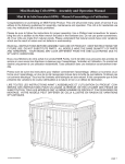
DongleVAULT
TM
Furaxa, Inc.
34 Canyon View Drive
Orinda, California 94563
Asset Protection & Productivity
Dongle Vault User Manual
Model 4C4D4P
Safety Instructions
WARNING: TO PREVENT FIRE OR SHOCK HAZARDS, DO NOT EXPOSE THE AC ADAPTER TO
MOISTURE.
CAUTION: OBSERVE THE FOLLOWING RULES REGARDING THE USE OF THIS UNIT.
1.
2.
3.
4.
Operate only from the power source specified on the unit.
Use only the AC adapter supplied with the Dongle Vault.
Avoid damaging the AC adapter.
Connect only to computer PARALLEL ports, PARALLEL port dongles and PARALLEL
port printers using PARALLEL port cables.
5. Do NOT use with RS232 or serial ports or any interface other than a PARALLEL port.
6. Do not allow liquids inside the device.
7. Do not disassemble this product. If service or repair is required take the unit to an
authorized Dongle Vault service agent.
Caution: Changes or modifications to this device not approved by Furaxa, Inc. may void the warranty.
Operating Instructions
Components
The Dongle Vault™ is shipped with the following:
1. One (1) Dongle Vault™
2. One (1) power adapter
3. One (1) IEEE1284 parallel port extension cable
4. One (1) mounting accessory pack with:
- Two (2) 2” hex head woodscrews
- Four (4) 1” hex head woodscrews
- Four (4) #6 2-3/8” hollow wall anchors
- Four (4) #8 flat cut washers
If you are missing an item listed above please e-mail Customer Service at [email protected].
Installation
Dongle Vault™ Installation
1. Select an area on a wall, desk or table to mount the Dongle Vault™. The location should provide
convenient access to your computer workstation(s) and printer(s), and should be chosen to
minimize cable length. Cables should be held to 15 feet or less in length for optimum performance.
2. For Wall-Mounting
a. Orient the Dongle Vault™ horizontally in the selected location on the wall.
-1-
b. Open the front panel and mark the desired location of the screws at the appropriate position in
the slots at the rear of the Dongle Vault™. If possible, two screws should penetrate a stud in
the wall.
For Mounting with a Stud
c. Remove the Dongle Vault™ from the desired mounting location. In each of the two screw
positions not over a stud, tap a hollow wall anchor into the wall with a hammer. Continue
tapping in the anchor until the teeth penetrate the surface of the wall. Turn the screw clockwise
until a definite resistance is felt. Remove the screw from the anchor by turning it counter
clockwise.
d. While holding the Dongle Vault™ flush against the wall over the pre-determined screw
positions, secure the unit to the stud with the two 2” hex head woodscrews and two washers.
Tighten the wood screws with a hex head wrench until the unit is firmly held against the wall.
Then secure the opposite side of the Dongle Vault™ by tightening a hollow wall anchor screw
with a #8 washer through each of the remaining slots in the rear of the Dongle Vault™ case.
For Mounting without a Stud
e. Remove the Dongle Vault™ from the desired mounting location. In each of the four screw
positions (not over a stud), tap a hollow wall anchor into the wall with a hammer. Continue
tapping in the anchor until the teeth penetrate the surface of the wall. Turn the screw clockwise
until a definite resistance is felt. Remove the screw from the anchor by turning it counter
clockwise.
f.
While holding the Dongle Vault™ flush against the wall over the pre-determined screw
positions, secure the unit to the wall by tightening a hollow wall anchor screw with a #8 washer
through each of the slots in the back of the Dongle Vault™ case.
3. For Desk or Table-Mounting
a. Orient the Dongle Vault™ horizontally or vertically to best fit the selected location.
b. Open the front panel and mark the desired location of the woodscrews at the appropriate
position in the slots at the rear of the Dongle Vault™.
c. Remove the Dongle Vault™ and drill tap holes in the desk at the desired locations to
accommodate the woodscrews. Do not attempt to drill through the Dongle Vault™ slots, as this
can damage the unit.
d. Replace the Dongle Vault™ in the desired location and insert a 1” hex head woodscrew with a
washer through the each of the back slots in the tap holes. Secure the Dongle Vault™ in place
by tightening the woodscrews with a hex head wrench until the unit is firmly held to the desk or
table.
Dongle Installation
1. Ensure that the Dongle Vault™ is unplugged from its power source.
2. Open the front panel.
3. Place the selected dongle in the connector inside the Dongle Vault™ nearest the computer port.
Begin with the connector marked “Dongle 1”, then “Dongle 2”, etc. You may need to disconnect the
short ribbon cable from the DB25 connector before installing the dongle.
4. Connect the other end of the dongle to the short ribbon cable attached to the opposite port inside
the Dongle Vault™.
5. Repeat steps 1 – 4 above to install additional dongles.
6. Additionally, dongles may be attached to the external parallel ports marked for printers 1 to 4 to
provide further dongle capacity outside the vault.
CAUTION: A ribbon cable must be connected to the end dongle in each bay or to the dongle socket in
empty bays. If a ribbon cable in one or more bays is not properly connected, one or more
parallel port devices may not be accessible to users.
-2-
NOTE:
Up to three dongles may be stacked in each bay so a computer can access multiple software
dongles without switching connections.
7. Close the front panel of the Dongle Vault™ and secure the unit with a padlock.
8. Insert the cord from the AC adapter into the unit power jack, and plug the AC adapter into an AC
wall outlet.
Computer and Printer Installation
1. Connect your computer system’s parallel port output to the Dongle Vault™ using an IEEE1284
compliant parallel port cable beginning with the port marked “Computer 1”, then “Computer 2”, etc.
For best results, the parallel port cable should not be longer than 15 feet.
2. Connect your printer (optional) to the Dongle Vault™ using an IEEE1284 compliant parallel port
cable beginning with the port marked “Printer 1”, then “Printer 2”, etc.
3. Repeat steps 1 & 2 above to install additional computers and printers.
Operation
1. Ensure that the desired computers, dongles and printers are properly connected to the Dongle
Vault™.
2. Ensure that the Dongle Vault™ AC adapter is plugged into an AC wall outlet. The Dongle Vault™
will by default power-up in the 1-1, 2-2, 3-3, 4-4 configuration for both dongles bays and printers
(i.e. Computer 1 is connected to Dongle 1, and Computer 1 is connected to Printer 1; Computer 2 is
connected to Dongle 2, and Computer 2 is connected to Printer 2; etc.) Please see diagram below.
Dongle Vault™ at Power-Up
CMP1
CMP2
CMP3
CMP4
PRINTER 4
PRINTER 3
PRINTER 2
PRINTER 1
DONGLE
DONGLE
DONGLE
DONGLE
CMP1
CMP2
CMP3
4
3
2
1
CMP4
3. Turn on the selected printers and computers.
4. To select a computer-dongle configuration, depress the button that connects the appropriate
computer port to the appropriate dongle port. The LED corresponding to the selected button will
illuminate when a valid connection has been established. Any prior connections with the specified
dongle or computer will be disconnected and the corresponding LEDs will go dark.
For example, to connect a computer installed in connector “Computer 2” with a dongle installed in bay
“Dongle 1” from the power-up configuration, one would depress the “DONGLE 1” button in the “CMP2”
bank of buttons. The “DONGLE 1” LED in the “CMP2” LED bank will illuminate when the connection is
made, and the “DONGLE 2” LED in the “CMP2” LED bank will go dark. Similarly, the “DONGLE 1” LED
in the “CMP1” LED bank will go dark. Thus, the prior Computer 1-Dongle 1 and Computer 2-Dongle 2
connections are broken when the Computer 2-Dongle 1 connection is established. Notice also that
Computer 1 is now unassociated with any dongle. Please see the following diagram.
-3-
Switching from the Power-Up State to a
Computer 2-Dongle 1 Connection
CMP1 CMP2 CMP3 CMP4
PRINTER 4
PRINTER 3
(2.) Computer 2 to
Dongle 2 LED
goes dark
PRINTER 2
PRINTER 1
CMP1
CMP2
CMP3
CMP4
PRINTER 4
PRINTER 3
PRINTER 2
PRINTER 1
(3.) Computer 1 to
Dongle 1 LED
goes dark
DONGLE
DONGLE
DONGLE
DONGLE
CMP1
CMP2
CMP3
4
3
2
1
CMP4
DONGLE 4
(4.) Computer 2 to
Dongle 1 LED
illuminates
DONGLE 3
DONGLE 2
DONGLE 1
CMP1 CMP2 CMP3 CMP4
(1.) Computer 2 to
Dongle 1 button
5. Similarly, to connect a printer to a computer, depress the button that connects the appropriate
printer port to the appropriate computer port. The LED corresponding to the selected button will
illuminate when a valid connection has been established.
For example, to connect a printer installed in the “Printer 4” connector with a computer installed in
the “Computer 2” connector, depress the “PRINTER 4” button in the “CMP2” bank of buttons. The
“PRINTER 4” LED in the “CMP2” button bank will illuminate when a connection is made. Likewise,
the LED corresponding to the previous Computer 2 printer connection will go dark. Please see the
following diagram.
Switching to a Computer 2-Printer 4 Connection
CMP1 CMP2 CMP3 CMP4
PRINTER 4
PRINTER 3
(1.) Printer 4 to
Computer 2
button
(3.) Printer 4 to
Computer 2
LED
illuminates
PRINTER 2
PRINTER 1
CMP1
CMP2
CMP3
CMP4
PRINTER 4
PRINTER 3
PRINTER 2
PRINTER 1
DONGLE
DONGLE
DONGLE
DONGLE
(2.) Printer 2 to
Computer 2
LED goes
dark
CMP1
CMP2
CMP3
4
3
2
1
CMP4
DONGLE 4
DONGLE 3
DONGLE 2
DONGLE 1
CMP1 CMP2 CMP3 CMP4
INTENDED USE: The matrix switch architecture of the Dongle Vault™ permits any combination of valid
concurrent connections between the attached devices and the dongles housed within
the unit. While multiple dongles can be accessed by multiple users concurrently, any
single dongle or dongle stack may only be connected to one computer at a time.
The Dongle Vault™ is sold for the purpose of protecting software investments against
loss and theft. The Dongle Vault™ is intended for licensed software users only and
must not be used in violation of the terms and conditions of a license agreement.
-4-
Troubleshooting Guide
Problem
Cause
Action
No power (No lit LEDs)
Is the AC adapter unplugged, or its
power cord disconnected?
Insert the AC adapter into a wall outlet,
and be sure that the adapter cord is
plugged into the Dongle Vault™.
Unable to access a
software license or
program
Is the AC adapter unplugged, or its
power cord disconnected?
Insert the AC adapter into a wall outlet,
and be sure that the adapter cord is
plugged into the Dongle Vault™.
Is a parallel port cable seated properly
in the correct computer and Dongle
Vault™ parallel ports?
Double check the connection of the
parallel port cable with the computer
parallel port connector and the correct
Dongle Vault™ computer connector.
Is the dongle seated properly in the
dongle port?
Disconnect and reconnect the dongle in
the selected dongle port connector.
Have the correct buttons connecting
the chosen computer-dongle
combination been selected?
Select the button corresponding to the
chosen computer-dongle combination.
The LED corresponding to the desired
connection should illuminate. See the
Operation section of the user manual for
detailed instructions on selecting specific
computer-dongle combinations.
Is the AC adapter unplugged, or its
power cord disconnected?
Insert the AC adapter into a wall outlet,
and be sure that the adapter cord is
plugged into the Dongle Vault™.
Is a parallel port cable seated properly
in the correct computer and Dongle
Vault™ parallel ports?
Double check the connection of the
parallel port cable with the computer
parallel port connector and the correct
Dongle Vault™ computer connector.
Is the dongle seated properly in the
dongle port?
Disconnect and reconnect the dongle in
the selected dongle port connector.
Is a parallel port cable seated properly
in the correct printer and Dongle
Vault™ parallel ports?
Double check the connection of the
parallel port cable with the printer parallel
port connector and the correct Dongle
Vault™ printer connector.
Have the correct buttons connecting
the chosen computer-dongle and
computer-printer combinations been
selected?
Select the buttons corresponding to the
chosen computer-dongle and computerprinter combinations. The LEDs
corresponding to the desired connections
should illuminate. See the Operation
section of the user manual for detailed
instructions on selecting specific
computer-dongle and computer-printer
combinations.
Unable to access a
printer
-5-
Warranty & Service
Limited Warranty
Furaxa, Incorporated (“Furaxa”) warrants this product against defects in material and workmanship, as follows:
1.
2.
For a period of one (1) year from the date of purchase, Furaxa will repair product defects free of charge.
In addition, Furaxa will supply, at no charge, new or rebuilt replacements for defective parts for a period of
one (1) year from the original date of purchase.
To obtain warranty service, you must take or deliver the product prepaid, to a Furaxa service facility. If repairs
are made to this product by anyone other than an authorized Furaxa service agent, the warranty is void.
This warranty does not cover cosmetic damage, and damage due to acts of God, accident, misuse, abuse, or
negligence to this product.
Furaxa makes neither express nor implied claims as to the security of the Dongle Vault or components that
may be used with it. This warranty does not cover the damage or loss, from theft or otherwise, of components
(e.g. dongles) used in conjunction with the product.
This warranty is only valid in the United States of America. Proof of purchase in the form of a bill of sale or
receipted invoice, which is evidence that the unit is within the warranty period, must be presented to obtain
warranty service.
REPAIR OR REPLACEMENT AS PROVIDED UNDER THIS WARRANTY IS THE EXCLUSIVE REMEDY OF
THE CONSUMER. FURAXA SHALL NOT BE LIABLE FOR ANY INCIDENTAL OR CONSEQUENTIAL
DAMAGES FOR BREACH OF ANY EXPRESS OR IMPLIED WARRANTY ON THIS PRODUCT. EXCEPT TO
THE EXTENT PROHIBITED BY APPLICABLE LAW, ANY IMPLIED WARRANTY OF MERCHANTABILITY OR
FITNESS FOR A PARTICULAR PURPOSE ON THIS PRODUCT IS LIMITED IN DURATION TO THE
DURATION OF THIS WARRANTY.
Service
Please refer to the troubleshooting guide in these instructions before calling customer service. If you are
unable to correct a problem after reviewing the operating instructions and troubleshooting guide, please
go to the customer service link at www.furaxa.com/Support.htm
Specifications
Power source
6 volt AC adapter with 500mA output current
Ports
8 x parallel IEEE1284
Connectors
Computer Output:
Parallel Port Output:
Dimensions
Length:
Width:
Height:
Weight
4.9 lbs
4 male 25 pin D-sub (DB25)
4 male 25 pin D-sub (DB25)
13.4 inches
7.8 inches
1.4 inches
-6-