1
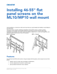
ML10/MP10 40-65” LCD Video Wall Mount
Instruction Sheet
The ML10/MP10 is a full-service video wall mount that can accommodate LCD flat panels between
40" to 65" diagonal. The ML10 mount is used for landscape orientations and the MP10 mount is used
for portrait orientations. The modular mount system features an innovative pull-out/prop-open hinge
mechanism that provides rear screen access, the ability to adjust alignment in XYZ axis and wall plate
spacers that set each mount into position.
For details, see Spacer Kit Instruction Sheet (P/N: 020-100728-xx).
ML10 – Landscape
ML10/MP10 LCD Video Wall Mount Instruction Sheet
020-100726-05 Rev. 1 (07-2013)
MP10 – Portrait
1 of 22
FEATURES
• Modular mount for large video wall display configurations.
• Tool-less adjustments of panels for optimal gaps.
• Spring-loaded mechanisms secure displays.
• Pull-out/prop-open mechanism provides quick service access.
• Integrated cable management tie-backs make display-to-display cabling simple.
• Included security hardware prevents the mount from extending out from the wall.
• Adjustable VESA® mounting hole patterns in 100 mm (3.9”) increments, starting at 200 x 200 mm
(7.9” x 7.9”) up to 700 x 400 mm (27.5” x 15.7”) for ML10 LCD mounts. Additional patterns
supported with adapter plates.
• Adjustable VESA® mounting hole patterns in 100 mm (3.9”) increments, starting at 200 x 200 mm
(7.9” x 7.9”) up to 600 x 400 mm (23.6” x 15.7”) for MP10 LCD mounts. Additional patterns
supported with adapter plates.
KITS REQUIRED
• LCD Mount 40-65” ML10 (Landscape)
P/N: 135-101103-xx
• LCD Mount 40-65” MP10 (Portrait)
P/N: 135-104106-xx
OPTIONAL KITS
• Spacer Kit 55” ML10 (Landscape)
P/N: 135-102104-xx
• Spacer Kit 55” MP10 (Portrait)
P/N: 135-107109-xx
OTHER AVAILABLE RESOURCES
• LCD Panel FHD551-X User Manual (P/N: 020-100713-xx)
• Spacer Kit Instruction Sheet (P/N: 020-100728-xx)
TOOLS REQUIRED
• Stud finder (edge-to-edge stud finder is recommended)
• Phillips® screwdriver
• Drill
• 5/16” (8 mm) bit for concrete and cinder block walls
• 5/43” (4 mm) bit for wood stud walls
• Level
2 of 22
ML10/MP10 LCD Video Wall Mount Instruction Sheet
020-100726-05 Rev. 1 (07-2013)
WARNINGS AND CAUTIONS
• Do not begin installation until you have read and understood the instructions and
warnings outlined in this document.
• This product should only be installed by someone of good mechanical aptitude.
• Make sure that the supporting surface will safely support the combined load of the
equipment and all attached hardware and components.
• Never exceed the Maximum Load Capacity of 125 lbs (57 kg).
• Extreme care must be taken when pushing the mounted display into its locked
position. Always handle the display on the opposing corners of the frame to avoid
direct contact with the LCD glass.
• If mounting to wood wall studs, make sure that the mounting screws are anchored
into the center of the studs. Use of an “edge-to-edge” stud finder is highly
recommended.
• Always use an assistant or mechanical lifting equipment to safely lift and position the
equipment.
• Tighten screws firmly, but do not overtighten. Overtightening can damage the items,
greatly reducing their holding power.
• This product is intended for indoor use only. Use of this product outdoors can lead to
product failure and personal injury.
TYPES OF INSTALLATIONS
Wall Construction
Hardware Required
•
•
•
•
•
•
•
Included
Included
Included
Included
Contact Qualified Professional
Contact Qualified Professional
Contact Qualified Professional
Wood Stud
Wood Beam
Solid Concrete
Cinder Block
Metal Stud
Brick
Other
ML10/MP10 LCD Video Wall Mount Instruction Sheet
020-100726-05 Rev. 1 (07-2013)
3 of 22
ML10/MP10 REQUIRED PARTS
Description
Qty.
A
Pull out mount assembly
1
B
Adapter Bracket
2
C
#14 x 2.5” hex head woodscrew
4
D
Concrete anchor
4
E
Fender washer
4
F
Nylon shoulder washer
4
G
M5 x 10 mm socket pin type-F screw
2
H
M6 x 12 mm socket pin screw
4
I
M8 x 15 mm socket pin screw
4
J
4mm Allen wrench
1
/
Mesh sleeve (not shown)
1
/
Cable tie (not shown)
2
ML10
A
B
C
D
E
F
G
H
I
J
ML
10
A
B
MP
4 of 22
MP10
10
ML10/MP10 LCD Video Wall Mount Instruction Sheet
020-100726-05 Rev. 1 (07-2013)
INSTRUCTIONS
This section explains how to install and connect the FHD551-X LCD Panel to the video wall mount.
For information on the LCD panel, refer to the LCD Panel FHD551-X User Manual (P/N: 020100713-xx). Illustrations are graphical representations only and are provided to enhance the
understanding of the written material.
INSTALLATION TO WALL STUD
• Tighten wood screws so that the wall plate is firmly attached, but do not
overtighten. Never tighten in excess of 80 in-lbs (9Nm).
• Hardware provided is for attaching the mount through standard thickness drywall or
plaster into wood studs. Installers are responsible to provide the hardware for other
types of mounting situations.
1. Use a stud finder to locate the
edges of the stud. Use of an “edgeto-edge” stud finder is highly
recommended. Based on their
edges, draw a vertical line down
the stud center.
Landscape Orientation
Wood stud
2. Place the pull out mount assembly
on the wall to use as a template.
3. Make sure the pull out mount is
level and mark the center of the 4
mounting holes. Make sure that the
mounting holes are on the stud
center line. Drill four 5/32" (4 mm)
diameter holes 2-1/2" (65 mm)
deep.
4. Make sure that the pull out mount
assembly is level, secure it using 4
#14 x 2.5" wood screws and fender
washers.
Pull out mount assembly
Fender washer
Wood screw *
* Make sure there is a minimum 16” (406.4 mm) horizontal distance between the #14 x2.5” screws.
Portrait Orientation
Wood stud
Pull out mount assembly
Fender washer
Wood screw*
ML10/MP10 LCD Video Wall Mount Instruction Sheet
020-100726-05 Rev. 1 (07-2013)
5 of 22
INSTALLATION TO SOLID CONCRETE OR CINDER BLOCK
• When installing wall mounts onto cinder blocks, verify that you have a minimum of 13/8" (35 mm) of actual concrete thickness in the hole to be used for the concrete
anchors. Do not drill into mortar joints. Be sure to mount in a solid part of the block,
generally 1" (25 mm) minimum from the side of the block. Cinder block must meet
ASTM C-90 specifications. It is suggested that a standard electric drill on slow setting
is used to drill the hole instead of a hammer drill to avoid breaking out the back of
the hole when entering a void or cavity.
• Concrete must be a minimum of 2000 psi density. Lighter density concrete may not
hold the concrete anchor.
• Make sure that the wall will safely support 4 times the combined load of the
equipment and all attached hardware and components.
• Tighten screws so that the wall plate is firmly attached. Never tighten in excess of 80
in lbs (9Nm).
• Always attach concrete expansion anchors directly to load-bearing concrete.
• Never attach concrete expansion anchors to concrete covered with plaster, drywall,
or other finishing material. If mounting to concrete surfaces covered with a finishing
surface is unavoidable, the finishing surface must be counter bored, as shown in the
image below. Make sure concrete anchors do not pull away from the concrete when
tightening screws. If plaster/drywall is thicker than 5/8" (16 mm), custom fasteners
must be supplied by the installer.
CUTAWAY VIEW
Mounting to concrete surface with a finishing surface
6 of 22
concrete
wall
plate
concrete
plaster/
drywall
ML10/MP10 LCD Video Wall Mount Instruction Sheet
020-100726-05 Rev. 1 (07-2013)
1. Make sure that the pull out mount assembly is level – use it as a template to mark 4 mounting
holes.
2. Drill four 1/4” (6 mm) diameter holes to a minimum depth of 2.5” (64 mm).
3. Insert anchors into the holes flush with the wall.
4. Place the pull out mount assembly over the anchors and secure it with four #14 x 2.5” screws, and
fender washers.
5. Level and then tighten all fasteners.
Landscape Orientation
Solid concrete
Cinder block
Anchors
Fender
washers
#14 x 2.5” *
screws
Pull out mount assembly
* Make sure there is a minimum 16” (406.4 mm) horizontal distance between the #14 x2.5” screws.
Portrait Orientation
Solid concrete
Anchors
Cinder block
Fender
washers
#14 x 2.5” *
screws
concrete
surface
Pull out mount assembly
E
Drill holes and insert anchors (E).
F
G
H
Place plate (F) over anchors (G) and secure with screws (H).
Tighten all fasteners.
ML10/MP10 LCD Video Wall Mount Instruction Sheet
020-100726-05 Rev. 1 (07-2013)
7 of 22
INSTALLATION TO F100 FRAME
Verify that the combined load of the equipment and all attached
hardware and components do not exceed the maximum load, as specified in the P100
Pedestal and F100 Frame Installation Manual (P/N: 020-100734-xx).
1. Make sure all components within the video wall are level, starting with the P100 Pedestal. If the
floor surface is not level adjust the feet on the pedestal. For details, see P100 Pedestal and F100
Frame Installation Manual (020-100734-xx).
2. Install the F100 Frame onto the pedestal. See P100 Pedestal and F100 Frame Installation
Manual (020-100734-xx).
NOTE: If the F100 Frame is used as stand alone unit it must be leveled before securing the wall
mount.
3. Before installing the wall mount use a standard level to check alignment on the horizontal and
vertical edge of the frame.
4. Position the wall mount within the center of the frame, aligning it with the mounting holes.
8 of 22
ML10/MP10 LCD Video Wall Mount Instruction Sheet
020-100726-05 Rev. 1 (07-2013)
5. Tighten the wall mount to the F100 Frame using the 4 M6 screws. Never tighten in excess of 80 inlbs (9Nm).
Front View
F100 frame
Wall mount
M6 screw (1 of 4)*
Back View
* M6 screws provided with F100 frame hardware kit (P/N: 000-102673-xx
6. For good screen planarity within a video wall adjust the top knob of the adapter bracket to achieve
a 5 mm (0.19”) gap.
ML10/MP10 LCD Video Wall Mount Instruction Sheet
020-100726-05 Rev. 1 (07-2013)
9 of 22
7. Adjust the bottom knob of the adapter bracket to achieve a 10 mm (0.39”) gap. If further
adjustment is required, leave a 1 mm (0.04”) minimum clearance to allow the bracket to be easily
released.
8. Mount the adapter bracket and use a level to check whether or not it is flush.
10 of 22
ML10/MP10 LCD Video Wall Mount Instruction Sheet
020-100726-05 Rev. 1 (07-2013)
9. Turn the knobs located on the bottom of the mount to adjust the position until it is vertically
centered.
10. Check that the mount is level. If necessary fine adjust the vertical position.
ML10/MP10 LCD Video Wall Mount Instruction Sheet
020-100726-05 Rev. 1 (07-2013)
11 of 22
11. To avoid damage to the display it is advised to leave a minimum 1 mm (0.04”) gap so the weight
of the panels do not rest on the panels underneath. It may be necessary to re-adjust the vertical
position to prevent this.
12. Always adjust the X position of panels individually versus pushing an entire row left to right. For
example, if you are constructing a 3x3 video wall push the panels individually from the right and
left sides, towards the center of the wall.
12 of 22
ML10/MP10 LCD Video Wall Mount Instruction Sheet
020-100726-05 Rev. 1 (07-2013)
ATTACH ADAPTER BRACKETS TO DISPLAY
13. Attach the adapter brackets to the back of the display using 4 M6 x 12 mm socket pin screws with
a nylon shoulder washer, or 4 M8 x 15 mm socket pin screws, as shown below.
NOTE: The hardware to attach the dedicated plates to the mount are included with the dedicated
plates.
Landscape Orientation
Display
Washer
Adapter brackets
400 mm
Socket pin screw
MAX VESA-700 mm
MIN VESA-200 mm
300 mm 200 mm
PLP
Portrait Orientation
MAX VESA-400 mm
MIN VESA-200 mm
Display
Adapter brackets
Washer
Socket
pin screw
400 mm
200 mm
300 mm
600 mm
ML10/MP10 LCD Video Wall Mount Instruction Sheet
020-100726-05 Rev. 1 (07-2013)
13 of 22
ATTACH ADAPTER BRACKETS TO DISPLAY CARRIAGE
14. Slide the adapter brackets into position. Loosely fasten in place using the security screw, as shown
below.
NOTE: Once the display is located in the desired position (±2”/50.8 mm from center), tighten the
security screws using a 4 mm allen wrench to lock it in place.
Landscape Orientation
Display carriage
Adapter bracket
Adapter bracket
Security screw
Portrait Orientation
Display carriage
Adapter bracket
Adapter bracket
Security screw
14 of 22
ML10/MP10 LCD Video Wall Mount Instruction Sheet
020-100726-05 Rev. 1 (07-2013)
PULL OUT MOUNT ASSEMBLY ADJUSTMENT
15. Use the illustrations below to determine the position of the display. Each knob can be adjusted
independently for fine tuning adjustments. Turn knob clockwise to raise side. Turn knob counterclockwise to lower side.
Portrait
Landscape
UP
ROTATE LEFT
DOWN
ROTATE LEFT
ROTATE RIGHT
DOWN
ROTATE RIGHT
ML10/MP10 LCD Video Wall Mount Instruction Sheet
020-100726-05 Rev. 1 (07-2013)
UP
15 of 22
ADAPTER BRACKET ADJUSTMENT
16. Reference the following 2 images for portrait and landscape to determine the displays position.
Each knob can be adjusted independently for fine tuning adjustments. Turn knob clockwise to
raise side. Turn knob counter-clockwise to lower side.
Adapter Bracket Adjustment – Portrait
16 of 22
IN
OUT
TILT FORWARD
BACK
BACK
BACK
TILT BACKWARD
TILT RIGHT
TILT LEFT
BACK
BACK
BACK
ML10/MP10 LCD Video Wall Mount Instruction Sheet
020-100726-05 Rev. 1 (07-2013)
Adapter Bracket Adjustment – Landscape
IN
OUT
TILT FORWARD
BACK
BACK
BACK
TILT BACKWARD
TILT RIGHT
TILT LEFT
BACK
BACK
BACK
ML10/MP10 LCD Video Wall Mount Instruction Sheet
020-100726-05 Rev. 1 (07-2013)
17 of 22
CABLE MANAGEMENT
17. Display cables can be routed through the top or bottom of the pull out mount assembly.
NOTES: 1) Use the mesh sleeve and cable ties for cable management. 2) The cable ties and cable
management slots on the pull out mount assembly can be used to secure the display cables.
Cable Management - Portrait
Ca
ble
ma
na
ge
me
nt
slo
ts
Detail 3
Cable Management - Landscape
Ca
ble
ma
na
ge
me
nt
slo
ts
Detail 3
18 of 22
ML10/MP10 LCD Video Wall Mount Instruction Sheet
020-100726-05 Rev. 1 (07-2013)
OPEN AND CLOSE PULL OUT MOUNT ASSEMBLY
NOTICE: To avoid damaging the LCD panel always release both locking tabs at the same time and
move the panel forwards evenly.
18. Release the locking tab to open the pull out mount assembly. Push or pull up on the locking tab, as
shown in the illustration below.
Pull Out Mount Assembly - Portrait
PULL UP
Locking
Tab
Locking Tab
PUSH UP
Pull Out Mount Assembly - Landscape
PULL UP
Locking
Tab
Locking Tab
PUSH UP
ML10/MP10 LCD Video Wall Mount Instruction Sheet
020-100726-05 Rev. 1 (07-2013)
19 of 22
OPEN ADAPTER BRACKETS
NOTICE: Two people are required when opening the adapter brackets, one to release the left-side
release cord and the other the right-side release cord.
19. Open the adapter brackets by pulling down on the long back release cords while pulling the bottom
of the display away from the wall. Once the back release cords are pulled, the kick stand will
engage.
Open Adapter Brackets - Portrait
Display Not
Shown for Clarity
Adapter bracket
Kick
Stand
Adapter bracket
Pull down back
release cords (long)
Open Adapter Brackets - Landscape
Display Not
Shown for Clarity
Adapter bracket
Kick
Stand
Adapter bracket
Pull down back
release cords (long)
20 of 22
ML10/MP10 LCD Video Wall Mount Instruction Sheet
020-100726-05 Rev. 1 (07-2013)
CLOSE ADAPTER BRACKETS
NOTICE: Take caution when closing the adapter brackets to ensure the LCD panel is not damaged.
Gently guide it back into place as you close the brackets.
20. You may need to slightly pull the display away from the wall to release the kick stand.
21. Close the adapter brackets by pulling down on the short front release cords, as shown below. Once
the short cords are pulled, the kick stand will disengage.
Close Adapter Brackets - Portrait
Display Not
Shown for Clarity
Adapter bracket
Kick
Stand
Adapter bracket
Pull down front
release cords (short)
Close Adapter Brackets - Landscape
Adapter bracket
Display Not
Shown for Clarity
Kick
Stand
Adapter bracket
Pull down front
release cords (short)
ML10/MP10 LCD Video Wall Mount Instruction Sheet
020-100726-05 Rev. 1 (07-2013)
21 of 22
SECURE PULL OUT MOUNT ASSEMBLY (OPTIONAL)
To prevent the locking tabs from releasing, secure using 2 M5 x 10 mm socket pin type-F screws.
Landscape Orientation
type-F
screw
Locking tab
Portrait Orientation
type-F
screw
Locking tab
22 of 22
ML10/MP10 LCD Video Wall Mount Instruction Sheet
020-100726-05 Rev. 1 (07-2013)