1
SPA
Site-Programmable HART® Loop
Monitor and Alarm
SPA
Site-Programmable HART®
Loop Monitor and Alarm
October 2001
224-741-00 D
All product names are registered trademarks of their respective companies.
HART is a registered trademark of the HART Communication Foundation.
2001 Moore Industries-International, Inc.
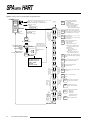
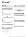
SPA HART Quickstart Menu
Use
or
push buttons to scroll
through menus and sub-menus.
Use the SELECT push button to
access menu and/or make a choice.
*Select Process
Variable to Display:
Primary
Second
Third
Fourth
VIEW
VIEW current settings
See View Menu, Figure 7
on page 11 of Users’ Manual.
SELECT
Front Panel
Push Buttons
Configure HART parameters:
Primary/Secondary
Burst/Normal
Number of Variables to Monitor
Number of Tries
Refer to Figure 10, page 14 of the Users’ Manual.
Password Jumper
installed in OFF position.
ENTER
PASS
SET
HART
SGNL
SRCE
Set the HART bit
that trips Relay #1
(0, 1, 2, 3, 4, 5, 7, or
any combination including all on or all off)
Refer to Figure 12, page 17 of the Users’ Manual.
FLT
SRCE
CONF
OPTS
Set the HART input Engineering Units
(distinct from the SPA display engineering units)
Refer to Figure 14, page 21 of the Users’ Manual.
SET
EGU
SCLE
INPT
“Capture” input scaling
from the connected HART device.
Refer to Figure 16, page 23 of the Users’ Manual.
Configure miscellaneous SPA parameters:
Input Linearization
HART Scaling
Engineering Units Displayed
HART Variable that serves as display source (Primary Variable or Current)
Relay #2 Function (Process variable or SPA Fault)
Upscale or Downscale drive on input failure (requires -AO option)
Refer to Figure 13, page 19 of the Users’ Manual.
Enter parameters for the custom scaling of HART variables.
Refer to Figure 15, page 22 of the Users’ Manual.
Scale the display for the HART parameters.
Refer to Figure 17, page 24 of the Users’ Manual.
Enter the factors for analog output scaling (-AO option required).
Refer to Figure 20, page 28 of the Users’ Manual.
TRIM
OUT
CONF
ALRM
View or change password code in SPA memory*.
Refer to Figure 23, page 31 of the Users’ Manual.
*If Password Jumper is installed in ON position,
valid password is required to view or make changes
to password code here.
Choose the HART variable to serve as the source
for each SPA relay installed.
Also choose the HART variable upon which to base the
SPA Analog Output (when equipped with the -AO option)
Refer to Figure 11, page 16 of the Users’ Manual.
ENTR
CURV
SCLE
OUT
Adjust the analog output
using external meter (-AO option required).
Refer to Figure 21, page 29 of the Users’ Manual.
Enter the password code to enable
settings changes.
Refer to Figure 9,
page 12 of the
Users’ Manual.
APLY
INPT
SCLE
DSPL
Enter up to 20 input linearization points.
Refer to Figure 18, page 25 of the Users’ Manual.
Password Jumper
installed in ON position.
PASS
WORD
CONF
EXIT
Set the parameters for all installed SPA relays:
Trip points
Deadbands
Alarm Delays
Latching/Non-Latching Functions
High vs. Low Alarm Functions
Refer to Figure 22, page 30 of the Users’ Manual.
Exit configuration menus and return to real-time display
of selected process variable.
*To access Second through Fourth Variables, you must properly configure the NUM VARS submenu of the SET HART menu.
Table of Contents
Introduction .................................................................................................... 1
About this Booklet ........................................................................................................... 1
The SPA HART ............................................................................................... 2
Inputs .............................................................................................................................. 2
Outputs............................................................................................................................ 2
Analog Output Option ......................................................................................................................... 2
Custom, 22-Point Linearization ................................................................................................................... 2
The SPA with HART is a digital Alarm ............................................................................ 2
Additional HART Information ............................................................................................................. 2
Specifications ................................................................................................ 3
SPA with HART Factory Defaults ................................................................................... 3
Ordering Information ....................................................................................................... 4
SPA Options ................................................................................................................... 4
Configuration ................................................................................................. 5
Configuration Equipment ................................................................................................ 5
Setting Jumpers and DIP Switches ................................................................................. 6
Password .............................................................................................................................................. 6
Failsafe/Non-failsafe ............................................................................................................................. 6
Current Source/Sink or Voltage ............................................................................................................. 6
Configuration Setup ........................................................................................................ 9
SPA Setup — Viewing What You Have ........................................................................ 11
SPA Setup — The Main Configuration Menu................................................................ 11
SPA Setup — Displaying Primary, Second, Third, and Fourth Variables ..................... 11
SPA Setup — Relay #1................................................................................................ 13
SPA Setup — Relay #2................................................................................................ 13
Contents (cont’d.)
SPA Setup — HART Configuration ............................................................................. 13
Set Address ....................................................................................................................................... 13
Primary/Secondary Master ............................................................................................................... 13
Normal/Burst Mode ........................................................................................................................... 15
Number of Variables ......................................................................................................................... 15
Number of TRYS (Tries) .................................................................................................................... 15
SPA Setup — Alarm Source ......................................................................................... 15
Analog Output Source ...................................................................................................................... 16
Relay Sources ................................................................................................................................... 16
SPA Setup — Fault Source .......................................................................................... 18
Bit 7 — Field Device Malfunction ..................................................................................................... 18
Bit 5 — Cold Start ............................................................................................................................. 18
Bit 4 — More Status Available ......................................................................................................... 18
Bit 3 — Primary Variable Analog Output Fixed .............................................................................. 18
Bit 2 — Primary Variable Analog Output Saturated ....................................................................... 18
Bit 1 — Non-Primary Variable Out of Limits ................................................................................... 18
Bit 0 — Primary Variable Out of Limits ........................................................................................... 18
SPA Setup — Configuring Miscellaneous Options ....................................................... 20
Toggle Linearization On/Off ............................................................................................................. 20
Customizing the Primary Variable Scaling ..................................................................................... 20
Setting the SPA Display Engineering Units .................................................................................... 20
Choosing the Source for the SPA Display ...................................................................................... 20
Setting the Function of SPA Relay #2 ............................................................................................. 20
Upscale/Downscale Drive ................................................................................................................. 20
Set Decimal Point ............................................................................................................................. 20
SPA Setup — Setting Engineering Units ...................................................................... 21
SPA Setup — Smart Scaling the HART Input ............................................................... 22
SPA Setup — Bench Scaling HART Input .................................................................... 23
SPA Setup — Scaling the HART Input Display ............................................................ 24
SPA Setup — Customizing Input Linearization ............................................................. 25
Enter the Number of Points to be used to Linearize the Input ...................................................... 26
Go Directly to a Particular Point for Adjustment ............................................................................ 26
Set the Value for the INPUT at Point ## ........................................................................................... 26
Set the Value for the DISPLAY at Point ## ...................................................................................... 26
Applications for Custom Linearization ............................................................................................ 26
Linearization Example ................................................................................................................................ 27
Changing Linearization with using Display Scaling ................................................................................. 27
Contents (cont’d.)
SPA Setup — Smart Scaling SPA Analog Output ........................................................ 28
SPA Setup — Trimming the SPA Analog Output .......................................................... 29
SPA Setup — Configuring the SPA Relays .................................................................. 30
AL 1 & AL 2 Config — Setting Alarm Delay .................................................................................... 32
AL 1 & AL 2 Config — Setting Latching/Non-Latching Alarm Function ........................................ 32
AL 2, 3, & 4 Config — Entering Trip Points .................................................................................... 32
AL 2, 3, & 4 Config — Capturing Trip Points .................................................................................. 32
AL 2, 3, & 4 Config — Entering Alarm Deadband ........................................................................... 32
AL 2, 3, & 4 Config — Entering Alarm Delay .................................................................................. 32
AL 2, 3, & 4 Config — Set High/Low Alarm Function ..................................................................... 33
AL 2, 3, & 4 Config — Set Latching/Non-Latching Alarm Function ............................................... 33
SPA Setup — Setting or Changing the SPA Password Code ...................................... 33
Installation ................................................................................................... 34
Connecting the SPA ..................................................................................................... 35
Grounding the SPA ....................................................................................................... 35
Housing ............................................................................................................................................. 36
Wiring ................................................................................................................................................ 36
Other Notes on Connecting the SPA ............................................................................................... 38
Other SPA Installation Information ................................................................................ 38
Operation ..................................................................................................... 39
Changing Settings ........................................................................................................ 39
LEDs ............................................................................................................................. 39
Important: Relays and LEDs—Working Together .......................................................................... 39
Manual Reset ................................................................................................................ 40
Error Codes................................................................................................................... 40
SPA WITH HART
About this Booklet
Introduction
This is the user’s manual for the Moore Industries’
SPA HART Loop Monitor and Alarm. The SPA HART
is a device that monitors a process input from a smart
HART device and provides up to four contact closure
outputs whenever the input falls outside a user-set
high or low trip point. SPAs are typically used to activate a warning light, bell, or buzzer; or to initiate a
system shutdown, thus acting as a simple, highly reliable means of safeguarding your process.
Wherever you see a “Note”, “Caution”, or
“WARNING” pay particular attention.
• A “Note” provides information to help you in avoiding
minor inconveniences during calibration,
installation, or operation of the SPA.
• A “Caution” provides information on steps to take in
avoiding procedures and practices that could risk
damage to the SPA or other equipment.
• A “WARNING” provides information on steps to take
in avoiding procedures and practices that could
pose safety risks to personnel.
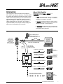
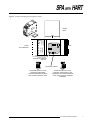
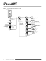
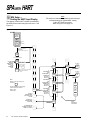
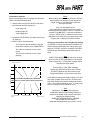
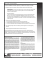
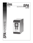
Figure 1. An Overview of the SPA with HART
HART
O
➤
0
➤
HART COMMUNICATOR
CAN BE CONNECTED
ANYWHERE ON THE LOOP
icator
➤
9
6
2
.
➤
HART FIELD
INSTRUMENT
(TEMPERATURE,
PRESSURE,
LEVEL, FLOW, OR
MULTIVARIABLE)
➤
8
5
1
Commun
➤
I
7
4
3
—
➤
DCS, SCADA,
PLC, ETC.
(HART OR
NON-HART)
4-20MA ANALOG SIGNAL WITH
HART DATA SUPERIMPOSED
HART
QUERY
HART DIGITAL
PROCESS AND
DIAGNOSTIC DATA
ALARM #1 – HART FAULT
WARNING
ANNUNCIATOR
ALARM #2 – SPA FAULT
OR PROCESS VARIABLE
VIEW
SPA
INDEPENDENT
EMERGENCY
SHUTDOWN
CONTROLLER
ALARM #3 – PROCESS VARIABLE
SELECT
ALARM #4 – PROCESS VARIABLE
OPTIONAL ANALOG OUTPUT
TIED TO ANY PROCESS VARIABLE
EVENT
RECORDER
25.1
deg-c
80.1
20.3
50.7
The Interface Solution Experts
1
SPA WITH HART
The SPA HART
The SPA with HART is a 4-wire (line or mains powered), site-programmable, digital process alarm. It
connects to a standard HART field device, and provides up to four, fully-configurable, contact-closure
outputs and one analog output based on “readings” of
the HART digital data. See Figure 1 for details.
The SPA can be user-set as either the Primary or
Secondary HART Master in the process loop. It can
provide transmitter excitation for the HART transmitter
it is monitoring; provide an auxiliary analog output
based on the HART-encoded digital input from the
Smart device; and can be used as an “on-site” indicator of trouble by virtue of it’s programmable LCD and
front panel multi-color LEDs.
Alarm #2 can be user set to trip either when the SPA
itself is malfunctioning (Refer to “SPA Setup—Relay
#2, page 13), when any one of the HART variables
varies outside a user-defined range, or if the Primary
Variable current (PVC) is too high or too low.
Alarms #3 and #4 of the 4-alarm SPA variant, are process variable alarms that are configured by the user
to trip when any one of the HART variables varies outside a user-defined range, or if the Primary Variable
current (PVC) is too high or too low.
Each of the SPA alarms can be configured for high,
low, failsafe, non-failsafe, latching, or non-latching
function. Each can also be programmed with a delay
and a deadband.
Analog Output Option
Inputs
The SPA with HART reads and can display:
• The Primary, Second, Third (tertiary), and Fourth
(quartic), HART Variable
• The Current (0-20mA) of the Primary HART
Variable
The SPA also provides an isolated, scalable 0-20mA
or 0-10V output proportional to the monitored process
variable.
Custom, 22-Point Linearization
The SPA input can be programmed from the front
panel keypad with up to 22 custom linearization points
for linearizing its display and/or its optional analog output.
and
• The scaling (zero and span) of the Primary
Variable
Additionally, the SPA with HART monitors its own
“health”. It constantly checks to make sure that internal programming is correct, and that it is receiving the
correct HART signal from the transmitter.
The SPA with HART is a DIGITAL Alarm
The SPA with HART bases all alarm functioning on its
reading of the digital data received from the Smart
device. Even its display (and its analog output, when
equipped with its –AO option) is based on the digital
information it processes.
Additional HART Information
Outputs
The SPA with HART can be ordered with either 2 or 4
alarm outputs.
In both the 2- and 4-alarm configuration, Alarm #1 is a
contact closure output that “trips” whenever there is a
problem with HART communications. (More on this in
the section of this manual that explains the SPA’s
monitoring of the HART Status Byte information,
pages 17 and 18.)
2
The Interface Solution Experts
For more information on HART protocol, we recommend referring to any of the documents available
from:
The HART Communications Foundation
9390 Research Boulevard, Suite I-350
Austin, Texas 78759-6540 U.S.A.
Telephone: (512) 794-0369
www.hartcomm.org
SPA WITH HART
Specifications
Performance Input Accuracy: Limited
by the accuracy of the
HART field instrument
Display Accuracy:
±1 digit
Deadband: Full display
range available; equal to
maximum input range in
user-set engineering units
Digital Response Time:
Defined by HART
protocol as 500
milliseconds (msec),
normal mode, 333 msec
in burst mode
Alarm Response Time:
Digital response time +
150 msec, max. (Defined
as time from the field
instrument’s reporting a
fault until the SPA alarm
is tripped)
Alarm Trip Delay:
Programmable from
0-120 seconds
Line Voltage Effect:
±0.005% of output span
for a 1% change in line
voltage (ac or dc)
Isolation: 1000Vrms
between case, input,
output (units with -AO
option) and power
terminals
Power Consumption:
2-4W, nominal; 6W,
maximum
Input Over-Range
Protection: ±5Vdc
Analog
Output
(-AO Option)
Performance
WITH ANALOG OUTPUT
Output Accuracy:
±0.03% of output span
(includes the combined
effects of linearity,
hysteresis, repeatability,
and adjustment
resolution)
Output Stability: ±0.1%
of calibrated span,
maximum, over 6 months
Output Response Time:
500 milliseconds, max.
Ripple (up to 120Hz):
Current output, 10mV
peak-to-peak max. when
measured across a 250Ω
resistor; Voltage output,
50mV peak-to-peak max.
Output Limiting:
117% of span max.,
115% of span typical
Load Effect: ±0.01% of
span from 0 to maximum
load resistance on current
output
Ambient Operating Range:
Conditions –25°C to +65°C
(–13°F to +149°F)
Storage Range:
–40°C to +80°C
(–40°F to +176°F)
Ambient Temperature
Effect: ±0.005% of
output span per °C max.
Relative Humidity:
0-95% non-condensing
RFI/EMI Protection:
30V/m - ABC ≤ 0.5% error
in reading when tested
according to SAMA
standard PMC 33.1;
20V/m when tested
according to
IEC1000-4-3-1995
Adjustments Front panel push buttons
control settings for zero,
span, alarm trip points,
HART parameters etc.;
Easy access internal
settings select current
(source or sink) or voltage
output, failsafe/nonfailsafe, and high/low
alarm functions; Internal
jumper and menu password protect parameter
settings
Indicators LCD: 2x4 character,
backlit, alphanumeric
readout accurate to the
nearest digit.
Range: –9999 to 9999;
Auto decimal positioning,
or programmable to one
or two places
LEDs: Dual-color TRIP
light (one for each relay)
shows green for nonalarm, red for alarm;
READY light indicates
normal operation,
extinguishes in the event
of any internal failure;
Dual-color INPUT light
shows green for input with
valid HART communications, red for communications failure; Dual-color
TRIP1 light shows green
for HART in non-alarm,
red for HART failure.
Weight 456 to 513 g
(16.1 to 18.1 oz)
Specifications subject to change without notice
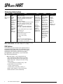
SPA with HART Factory Defaults
If you have placed or are going to place an order for
an SPA with HART without specifying any particular
model number, the unit you receive will be shipped
with the following “default” parameters:
• Alarm #2 functions as a Process Variable Alarm
trip (as opposed to a SPA “Health” alarm)
• The unit executes 3 retries in attempting to
establish communications with the connected
HART device, before returning a HART Fault
• The unit distinguishes the start of a polling
message with 5 preambles
• The unit’s Alarm #1 trips on any HART Fault bit
• Input scaling is 0-100%
• Input Linearization is OFF
• The unit functions as a HART Primary Master
• The unit functions in Normal Mode (as opposed to
Burst Mode)
All of these parameters can be changed by the user
with the instructions in this manual.
The Interface Solution Experts
3
SPA WITH HART
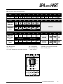
Ordering Information
Unit
Input
Output
Power
SPA
SiteProgrammable
Alarm
HART
Accepts
a HART
digital
protocol input
directly from
a HART
temperature,
pressure,
level, flow,
valve
positioner, or
multivariable
transmitter
(HART
version 5.4
and earlier)
2PRG Dual Relays
RELAY #1 is a HART instrument fault alarm
RELAY #2 configures as either a SPA
instrument fault alarm or as a process
variable alarm
U Universal,
4-wire (line)
power; accepts
any power input
range between
22-300Vdc or
90-260Vac
4PRG Quad Relays
RELAY #1 is a HART instrument fault alarm
RELAY #2 configures as either a SPA
instrument fault alarm or as a process
variable alarm
RELAY #3 is a process variable alarm
RELAY #4 is a process variable alarm
Process variable alarm relays configure
independently for:
High or Low Trip
Normally Open or Normally Closed
Failsafe or Non-Failsafe
Latching or Non-Latching
Trip Delay
(Relays are single-pole/double-throw
(SPDT), 1 form C, rated 5A @ 250Vac or
24Vdc, 50/60Hz, non-inductive)
When ordering, specify: Unit / Input / Output / Power / Options [Housing]
Model number example: SPA / HART / 4PRG / U / -AO [DIN]
SPA Options
The following list gives details for the options shown in
the Ordering Information table. For information on the
availability of any options not listed here, or for help in
equipping the SPA with the options best suited for
your application, call the factory, or your local Interface Solutions professional.
–AO Analog Output - When equipped with this
option, the SPA with HART provides an isolated
analog output proportional to its processing of its
digital, HART input. Settings for the SPA analog
output include:
• Current (0-20mA) or Voltage (0-10V); Also
programmable for narrower spans
• Source or Sink (Current)
• Reflect Primary, Secondary, Tertiary, or
Quartic, HART Variable, or Current of Primary
Variable; Reverse or direct relationship
4
The Interface Solution Experts
For CE
approved
units, specify
one of the
following:
24DC ±10%
117AC ±10%
230AC ±10%
Options
-AO Analog
output scaleable
for any range
between
0-20mA (4mA
span, min.) into
1200Ω or
0-10V (1V span,
min.) into 10KΩ
-DPDT Doublepole/double-throw
relays, 2 form C
relays, rated 5A
@ 250Vac, 50/
60Hz, noninductive (2PRG
output types only)
-HS Hermetically
sealed relays,
rated 0.5A @
117Vac and 2A
@ 28Vdc
Housing
DIN Universal
DIN-style
housing
mounts on
32mm
(EN50035)
G-type and
35mm
(EN50022) Top
Hat DIN-rails
SPA WITH HART
Configuration
In this manual, the term “configuration” is used to refer
to the following, four procedures:
1. Verifying that the unit’s internal jumpers are set to
provide Password Security for operational
settings
2. Setting the internal DIP switches to provide either
failsafe of non-failsafe alarm functioning (and
current or voltage output, if the SPA is equipped
with its -AO option)
3. Hooking up the SPA in a simple test setup that
enables the user to view unit settings in memory,
and to make whatever changes may be needed
according to the requirements of the intended
application
4. Making sure that the SPA “synchs up” properly
with a HART transmitter or calibrator, that it reads
all the variables of the digital signal correctly, and
that it provides the prescribed alarm(s) and/or
analog output and display, based on changes on
the input
Configuration Equipment
To configure and bench check the SPA with HART,
the following items will be needed (note that these
materials are not supplied by Moore Industries, but
should be readily available in those environments otherwise appropriate for instrument calibration.)
Table 1. Equipment for Configuring the SPA with HART
Equipment
Power Source
Multimeter
Needle-nosed
Pliers
Specifications
22-300Vdc, ±10%; or 90-260Vac, ±10%
Calibrated, Fluke Model 87 or equivalent,
accurate to ±0.025%. It is best to have two
of these; one to check for continuity (testing
contact-closure), and one to calibrate the
SPA analog output when –AO option is
installed.
Technicians pliers or tweezers for
positioning internal jumpers.
Slave HART
Field Device or
Field Device
Simulator
(optional)
THZ or TDZ HART Temperature Transmitter
or Model 275 HART Communicator. HART
input can be useful in calibrating the SPA,
but is not required.
Secondary
Power Source
(optional)
As required for powering the HART Slave
device, if used. Consult the manufacturer’s
specifications.
We test all of the instruments we sell on equipment
that is checked at least every six months for accuracy.
All our test equipment is accurate on the order of 3:1,
minimum. Every effort should be made to use the
most accurate equipment available to configure your
SPA prior to placing it into service.
Caution:
The internal circuitry of the SPA is vulnerable to
damage from electrostatic discharge.
Make sure to abide by all static safeguarding (ESD)
practices any time the SPA housing is to be opened;
especially when making changes to the jumper
settings or DIP switches inside the SPA.
The Interface Solution Experts
5
SPA WITH HART
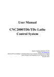
Setting Jumpers and DIP Switches
The following SPA with HART functions are governed
by the positioning of of the internal jumper and DIP
switches:
• Password - To “protect” the operational settings
of the SPA, make sure the Password Jumper
shown in Figure 2 is in the “ON” position. With
password protection ON, making changes to the
SPA configuration can only take place after
entering a two-digit, user-defined code (refer to
the Password menu explanation, page 33). With
password protection OFF, the user can make
changes freely to the SPA settings, including the
Password code itself.
• Failsafe/Non-failsafe - Set the appropriate DIP
switch to FAILSAFE in order to configure it to deenergize when in an alarm condition. Non-failsafe
alarms energize when tripped.
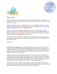
• Current Source/Sink or Voltage - If the SPA is
equipped with its -AO option, this DIP switch
setting determines whether the analog output is
current or voltage. If the output is to be current,
this switch setting also determines whether the
unit sinks or sources that current.
6
The Interface Solution Experts
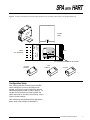
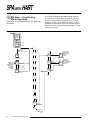
To make changes to, or to view the settings of the
SPA DIP switches and/or Password jumper, open
the access panel in the bottom of the SPA housing.
Figures 2, 3, and 4 show the access panel and locations of the jumpers and switches.
Note:
Jumpers are referred to as “”links” in some
countries. “DIP” is dual, in-line positioned switch.
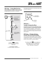
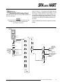
Figure 4 shows the location of the DIP switches for
setting the parameters of the SPA analog output. This
output is present only in those units equipped with the
–AO option.
SPA WITH HART
Figure 2. Accessing and Setting the SPA Password Jumper
BACK
(terminal
labeling)
GND
FRONT
SPA UNDERSIDE
POWER
AC OR DC
SLIDING
PANEL
NOTE: The 3 pins to the left
of the Password jumper pins are for
FACTORY USE ONLY.
DO NOT INSTALL JUMPERS ON
THESE PINS.
PASSWORD JUMPER
ON
PASSWORD SECURITY IS ON.
PASSWORD IS REQUIRED
TO MAKE PARAMETER CHANGES
AND TO VIEW PASSWORD CODE.
OFF
PASSWORD SECURITY IS OFF.
CHANGES CAN BE MADE TO ANY
PARAMETER, INCLUDING PASSWORD
CODE ITSELF, WITHOUT ENTERING
PASSWORD.
The Interface Solution Experts
7
SPA WITH HART
Figure 3. Accessing and Setting the SPA Failsafe/Non-Failsafe DIP Switches
AC OR DC
RELAY 1 RELAY 2 POWER
BACK
NO1
CM1
NC1
NO2
CM2
NC2
FRONT
SPA UNDERSIDE
GND
SET FAILSAFE/NON-FAILSAFE
1
2
3
4
= FAILSAFE
= NON-FAILSAFE
EXAMPLE:
ALARMS 1 & 2 = NON-FAILSAFE
ALARMS 3 & 4 = FAILSAFE
NOTE: THIS 4-POSITION SIP SWITCH MAY VARY IN LOCATION BASED ON THE TYPE OF SPA USED
8
The Interface Solution Experts
SPA WITH HART
Figure 4. Accessing and Setting the SPA with HART DIP Switches for Controlling Analog Output (-AO-equipped SPAs only)
BACK
(terminal
labeling)
GND
FRONT
SPA UNDERSIDE
POWER
AC OR DC
SLIDING
PANEL
SET CURRENT-SOURCE/SINK OR VOLTAGE
SOURCE
CURRENT
SINK
CURRENT
VOLTAGE
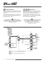
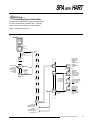
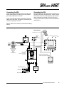
Configuration Setup
After verifying that all the internal jumper and DIP
switch settings are correct or otherwise set as
needed, use Figure 5 to hook up the SPA with the
calibration equipment listed in Table 1 (page 5). To
use the SPA’s transmitter excitation to power the
HART transmitter or simulator in the hookup, refer to
Figure 6 for the hookups.
Once hooked up and supplied with the appropriate
power, allow a few minutes for stabilization.
The Interface Solution Experts
9
SPA WITH HART
Figure 5. Hooking up the SPA with HART for Calibration
For a HART Transmitter, such as the THZ temperature
transmitter, the resistor must be >250 and <1100
For a HART Receiver, such as a valve positioner,
no resistor is necessary.
24Vdc
Power
+
Sensor
Input
HART
Field Device
or
Simulator
MANUAL
RESET
–
With -AO Option ONLY
Optional
+
+
R
MULTIMETER
–
–IN
+IN
+
–
Current
Output
–
Optional
+
NOTE: Either,
but not both
sets of input connections
may be used.
READY
TRIP 1
INPUT
TRIP 2
MULTIMETER
TRIP 3
–
TRIP 4
Optional
VIEW
SPA
GND
AC
COM
MULTIMETER
ACC
NC
NO
SELECT
AC or DC
POWER
Checks for
continuity
Optional
Figure 6. Hooking up the Transmitter Excitation on the SPA with HART for Calibration
R must be
Sensor
Input
HART
Field Device
or
Simulator
–
R
+INA
+
Optional
Equipment Hookup
for HART field device using
Standard SPA Transmitter
Excitation.
–INA
TXA
READY
INPUT
SPA
10
The Interface Solution Experts
250
and
1100
Voltage
Output
SPA WITH HART
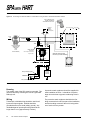
SPA Setup — Viewing What You Have
With the SPA set up as shown in Figure 5 (or 6), you
can run through the View Menu to check the settings
already present in unit memory. See Figure 7.
Figure 8 gives the breakout for the abbreviations used
in the SPA View Menu.
Figure 8. Understanding the SPA Relays’ LCD
Figure 7. Viewing the Settings in SPA Memory
PROCESS
VALUE
DISPLAY
VIEW
XXXX
ZERO
VIEW
XXXX
FULL
These are the settings for
output zero and full scale,
shown in user-set
engineering units.
They appear only when the
SPA is equipped with its
-AO Analog Output option
VIEW
If Relay #2 is configured
as a SPA Health alarm.
XXXX
AL2X
VIEW
AL2F
VIEW
2 Relays
installed (2PRG)
XXXX
AL3X
These are the settings for
each relay’s configuration.
See Figure 8 for a breakout
of abbreviations.
VIEW
XXXX
AL4X
VIEW
Notes:
The UP, DOWN, and SELECT
push buttons are inactive in the
VIEW menu.
XXXX
AL2X
Alarm
Number
Trip Point Setting
(in Engineering Units,
with any scaling)
F - Fault Alarm
H = High Alarm
L = Low Alarm
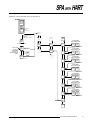
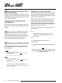
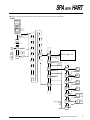
SPA Setup —
The Main Configuration Menu
Figure 9 gives an overview of the uppermost level of
the SPA menu system. All user-set operating parameters are arranged in hierarchical fashion, stemming
from somewhere on this ladder. To enter the submenus, scroll through the Main Menu, and press the
SELECT button when the display shows the desired
sub-menu title.
SPA Setup — Displaying Primary,
Second, Third, and Fourth Variables
From the Process Value Display, use the up/down
arrow buttons to select which variable you would like
the SPA HART to display. You can select from the
primary, second, third, and fourth variables.
Note:
The Second, Third, and Fourth Variables are
only available if they are selected in the
NUM VARS portion of the SET HART
menu. (See Figure 10, page 14)
No password is needed
to view the settings in SPA memory.
The Interface Solution Experts
11
SPA WITH HART
Figure 9. Moving Around in the SPA Main Configuration Menu
START
Selects which Process Variable to view: PV, FV, TV, or SV
NOTE: FV, TV, and SV are displayed only if
selected in NUM VARS in the SET HART menu.
PROCESS
VALUE
DISPLAY
VIEW Menu, Figure
7, page 11
VIEW
OR
NO
HART
If configured for use
with single variable
HART device.
If Password Jumper is
INSTALLED
(See Figure 2, page 7)
SET
HART
ENTER
PASS
SGNL
SRCE
If configured for use
with single variable
HART device.
If Password Jumper is
NOT INSTALLED
(See Figure 2, page 7)
SELECT
(If no HART
device
is connected.)
SET
HART
CONF
EXIT
USE UP AND DOWN TO
ADJUST DISPLAY TO
DESIRED
2-DIGIT PASSWORD
CODE.
RANGE COUNT IS
00 TO 99. DEFAULT IS 00.
SELECT
Both up and down
buttons
##
return to PASS
CONF
OPTS
If Password matches
code already in SPA
memory (see page 13).
CONF
OPTS
SET
EGU
If Password does not
match.
READ
ONLY
SCLE
INPT
SELECT
USER CAN VIEW
SETTINGS (EXCEPT FOR
PASSWORD CODE), BUT
CANNOT CHANGE
ANYTHING.
"READ ONLY MODE"
APLY
INPT
SCLE
DSPL
SCLE
OUT
TRIM
OUT
Set the HART bit (0, 1, 2, 3, 4, 5, or 7)
that trips relay #1.
Any combination can be set, including
all on and all off.
Configure SPA parameters for:
Input Linearization
HART Scaling
Display Engineering Units
Display Source (HART Variable
or Primary Variable Current)
Decimal Point
Relay #2 Function
(Process Variable trip or
SPA Fault)
Upscale or Downscale drive on
input failure (with -AO only)
Set the HART input engineering units
(distinct from SPA display engineering
units).
SCLE
INPT
Input the parameters for the custom
scaling of the HART variables.
APLY
INPT
"Capture" input scaling from
connected device.
SCLE
DSPL
Scale the display for the input HART
variables.
ENTR
CURV
Enter up to 20 linearization
points.
Not
visible
in
CONF
ALRM
Choose the source(s) for each relay
installed, and the source upon which
the analog output is to be based, if the
unit is equipped with the -AO option.
SET
EGU
If not
equipped with
-AO Analog
Output option.
Not
visible
in
SCLE
OUT
Enter analog output scaling
(if -AO option is installed).
TRIM
OUT
Adjust analog output
(if -AO option is installed).
CONF
ALRM
READ
ONLY
READ
ONLY
PASS
WORD
CONF
EXIT
or if
Password
Jumper is
installed
or if
Password
Jumper is
installed
The Interface Solution Experts
ENTR
CURV
If configured for
non Linearization.
If configured for
non Linearization.
If not equipped
with
-AO Analog
Output option.
SELECT
12
FLT
SRCE
FLT
SRCE
UP, DOWN, SELECT
##
PASS
SGNL
SRCE
Configure HART parameters:
Primary/Secondary Master
Set Address
Burst/Normal Mode
Number of Variables monitored
Number of tries to establish
communications before
returning "NO HART" message
PASS
WORD
Set SPA relay parameters:
Trip points
Deadbands
Alarm Delay
Latching/Non-latching
High/Low alarming
Choose password code.
SPA WITH HART
SPA Setup — Relay #1
Relay #1 on the SPA with HART is factory-set to “trip”
whenever the unit detects a fault in the connected
HART device. The relay provides a contact-closure
output based on the status of the HART device, monitoring the HART “Status Byte” several times a second.
Note:
The function of Relay #1 on the SPA with HART
cannot be changed.
The user can, however, set several operating
parameters that affect its function.
See Figure 10, page 14.
SPA Setup — Relay #2
Relay #2 on the SPA with HART can be user-configured to trip under one of two conditions. First, it can
be configured as a SPA “health” alarm, providing contact-closure output if there is a communications failure, or if the unit detects an error in its own memory or
processing.
Alternatively, it can be configured as a standard, digital process variable alarm. This configuration brings
the number of available process alarms to 3 in 4PRG
output SPA model variants.
The SPA is configured at the factory with its Relay #2
as a Process Variable alarm.
SPA Setup — HART Configuration
The first thing to set up in the SPA with HART are the
parameters that control how the unit “talks” to the
HART device it will be monitoring. Accordingly, this is
the first sub-menu accessible from the Main Configuration menu (see Figure 9, page 12).
Figure 10 shows the sub-menu for setting the HART
parameters.
Set Address
The HART procotol allows for up to fifteen different
HART transmitters to be placed on one loop. Use the
“Set Address” function to select the address of the
HART field device that the SPA is to monitor.
Primary/Secondary Master
The HART protocol is designed to take advantage of a
dual-master networking topology. This allows for two
communications masters on the loop, a Primary and a
Secondary.
The factory sets the SPA to function as the Primary
HART master by default.
Note:
Setting the SPA to function
as the Primary HART Master in the application
means that any other HART device in the loop
MUST be configured either
as a HART Secondary Master (1 per loop),
or as a HART Slave (up to 15 per loop).
Conversely, setting the SPA to function as the
Secondary Master allows other HART devices
to function either as a Primary Master (1 per loop),
or as Slaves (15 per loop).
Configuring more than one device on a single
loop as a Primary or Secondary HART Master
will cause a communications failure.
The Interface Solution Experts
13
SPA WITH HART
Figure 10. Configured the HART Alarm Parameters for the SPA
START
PROCESS
VALUE
DISPLAY
OR
(If no HART
device
is connected.)
NO
HART
UP = R A I S E
UP
SET
HART
SELECT
If Password Jumper is
INSTALLED
(See Main Menu, page 12.)
SELECT
SELECT
FLT
SRCE
SET
MSTR
##
PASS
SELECT
Both up and down
buttons
##
return to PASS
READ
ONLY
0 - 15 (DEFAULT = 0)
DOWN = L O W E R
PRIM
IF CONFIGURED
FOR USE WITH
SINGLE-VARIABLE
HART DEVICE.
SEC
SELECT
UP, DOWN, SELECT
USE UP AND
DOWN TO
RAISE/LOWER
DISPLAY TO
SHOW PASSWORD
CODE.
ADDR
00
SELECT
UP
SGNL
SRCE
ENTER
PASS
SET
ADDR
SELECT
UP AND DOWN
TOGGLE SELECTION
SET
FUNC
SELECT
BRST
NRML
UP AND DOWN
TOGGLE SELECTION
SELECT
NUM
VARS
UP = R A I S E
SELECT
X
VARS
1 - 4 (DEFAULT = 1)
DOWN = L O W E R
If Password does not
match.
SELECT
NUM
TRYS
UP = R A I S E
SELECT
X
TRYS
1 - 9 (DEFAULT = 3)
DOWN = L O W E R
EXIT
HART
SELECT
14
The Interface Solution Experts
SELECT
SPA WITH HART
Normal/Burst Mode
The SPA can be user-configured to operate either in
Normal HART mode, or in Burst HART mode.
In Normal mode, once communications have been established with a HART device, the SPA queries that
device twice per second, acting according to its setting either as the Primary or Secondary HART Master.
In Burst mode, once communications between the
SPA and the connected field device have been established, the SPA continuously “listens” for incoming
data from the field device without ever issuing a
query. In this mode, the SPA reads incoming data 3
times per second.
The factory default is Normal mode.
Number of Variables
The SPA is capable of monitoring the first 4 digital
process variables from the connected HART device.
Factory default is 1; the Primary HART variable only.
Note:
The setting for Number of Variables has an affect on
the number of selections available in
the Signal Source menu.
Choices in that menu for Secondary, Tertiary, and
Fourth (Quartic) variables as sources
for SPA Alarms (and analog output)
are shown only if the Number of Variables selection
in the Set HART menu is 2, 3, or 4, respectively.
Number of TRYS (Tries)
This setting allows the user to configure the SPA to
“poll” the communications bus, attempting to connect
to a field device from 1 to 9 times before returning the
“NO HART” message on the SPA, and issuing an
alarm from Relay #2 (if configured as a SPA “health”
alarm).
The factory default for the Number of Tries is 3.
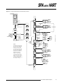
SPA Setup — Alarm Source
This is the sub-menu with which Alarms 2 (if configured as a Process Variable Alarm, refer to page 13),
3, and 4 are assigned those aspects of the HART input data upon which to base their functioning. Additionally, if the SPA is equipped with its -AO Analog
Output option, this sub-menu sets the HART variable
upon which it will be based.
This menu is only accessible on those SPAs that are
to process more than one HART variable. It is also
only accessible on SPAs with more than 2 relays
(4PRG output model variant).
Figure 11 shows the sub-menu for configuring the Signal Source for each SPA input and output available.
The Interface Solution Experts
15
SPA WITH HART
Analog Output Source
Relay Sources
This is the setting that determines which of the available HART parameters the SPA will base its analog
output upon.
These menus permit the user to configure the available SPA relays to respond to changes in any combination of the first 4 variables of the HART input.
If the -AO Analog Output option is not installed, this
section of the sub-menu is skipped, and the first selection will be for AL2 or AL3.
“PV” signifies the Primary HART variable, “SV” the
secondary variable, “TV” the third or tertiary variable,
and “FV” the fourth or quartic variable.
Note:
The selection for Primary Variable Current is
available only when configuring the signal source for
the analog output, and is only shown when the SPA
–AO option is present.
Note:
The selections for Secondary, Tertiary, and Fourth
(Quartic) variables as signal sources appear only if
the Number of Variables selection in
the Set HART menu is 2, 3, or 4, respectively
(see Figure 10, page 14).
Figure 11. Choosing the Sources for the SPA Relays
START
PROCESS
VALUE
DISPLAY
OR
(If no HART
device
is connected.)
NO
HART
If Password Jumper is
INSTALLED
(See Main Menu, page 12.)
ENTER
PASS
UP, DOWN, SELECT
##
PASS
SELECT
Both up and down
buttons
##
return to PASS
READ
ONLY
AOUT
SRCE
SET
HART
SELECT
USE UP AND
DOWN TO
RAISE/LOWER
DISPLAY TO
SHOW PASSWORD
CODE.
EXIT
SRCE
SGNL
SRCE
FLT
SRCE
If -AO Analog Output
option is not installed.
SELECT
If Relay
#2 is
configure
d as an
SPA
"Health"
alarm
SELECT
AL 2
SRCE
16
PVC
PV
SV
TV
FV
To next
relay to
be programmed.
SELECT
If Relays #3 and #4
are not present
(2PRG model variant)
AL 4
SRCE
SELECT
EXIT
SRCE
If Password does not
match.
PVC selection only appears when setting source for Analog Output, which
is present only when the -AO Analog Ouptut option is installed.
SV, TV, and FV are only displayed as selections when the accordant
number of variables is selected in "SET HART", "NUM VARS".
The Interface Solution Experts
SELECT
AL 3
SRCE
SELECT
NOTE:
SELECT
PVC
PV
SV
TV
FV
AOUT
SRCE
If Relays #3 and #4
are not present
(2PRG model variant)
SPA WITH HART
Figure 12. Choosing the HART Source for SPA Relay #1
START
PROCESS
VALUE
DISPLAY
OR
(If no HART
device
is connected.)
NO
HART
SET
HART
SELECT
If Password Jumper is
INSTALLED
(See Main Menu, page 12.)
ENTER
PASS
##
PASS
SELECT
Both up and down
buttons
##
return to PASS
READ
ONLY
EXIT
BITS
UP AND DOWN
TOGGLE SELECTION.
UP, DOWN, SELECT
USE UP AND
DOWN TO
RAISE/LOWER
DISPLAY TO
SHOW PASSWORD
CODE.
EXIT
SRCE
SGNL
SRCE
If Password does not
match.
FLT
SRCE
CONF
OPTS
SELECT
SELECT
SET
FLT
BIT
7
SELECT
SELECT
BIT7
ON
BIT7
OFF
SELECT
UP AND DOWN
TOGGLE SELECTION.
EXIT
SRCE
BIT
5
SELECT
BIT5
ON
BIT5
OFF
SELECT
SET
FLT
UP AND DOWN
TOGGLE SELECTION.
BIT
4
SELECT
BIT4
ON
BIT4
OFF
SELECT
UP AND DOWN
TOGGLE SELECTION.
BIT
3
SELECT
BIT3
ON
BIT3
OFF
SELECT
UP AND DOWN
TOGGLE SELECTION.
BIT
2
SELECT
BIT2
ON
BIT2
OFF
SELECT
UP AND DOWN
TOGGLE SELECTION.
BIT
1
SELECT
BIT1
ON
BIT1
OFF
SELECT
UP AND DOWN
TOGGLE SELECTION.
BIT
0
SELECT
BIT0
ON
BIT0
OFF
SELECT
SELECT
EXIT
BITS
BIT
7
The Interface Solution Experts
17
SPA WITH HART
SPA Setup — Fault Source
The settings in this sub-menu control the function of
the SPA relay #1, the HART monitor. The SPA’s first
relay, Alarm #1, is permanently dedicated to monitoring the function of the HART device and communications.
The user can choose among 7 HART conditions to
produce an alarm. Figure 12 is a map of this submenu. Any combination, including all bits or no bits
may be set.
Bit 7 — Field Device Malfunction
Set this bit ON to configure the SPA Relay #1 to trip
whenever it detects that a hardware error or failure
has occurred in the connected HART device.
Bit 5 — Cold Start
Set this bit to ON to configure the SPA Relay #1 to trip
whenever power to the HART device is interrupted. If
ON, this bit will also trip the alarm following a HART
Master Reset or Self Test command.
Bit 3 — Primary Variable Analog Output
Fixed
Set this bit to ON to configure the SPA Relay #1 to trip
whenever the HART device detects that its Primary
Variable (typically the analog output) is no longer responding to changes on its input, and is, in fact being
held at a predefined level.
Bit 2 — Primary Variable Analog Output
Saturated
Set this bit to ON to configure the SPA Relay #1 to trip
whenever the HART device detects that both its analog and digital representations of the Primary Variable
are outside rated operating limits, and no longer reflect the true sensor input.
Bit 1 — Non-Primary Variable Out of
Limits
Set this bit to ON to configure the SPA Relay #1 to trip
whenever the HART device detects that one of its ancillary
variables (pressure, temperature, etc.) is operating outside
the limits that can be effectively measured. HART Command
#48, “Read Additional Information” may be required to
determine which variable is causing the problem.
Bit 0 — Primary Variable Out of Limits
Bit 4 — More Status Available
Set this bit to ON to configure the SPA Relay #1 to trip
whenever the HART device reports a condition requiring HART Command #48, which is “Read Additional
Information”. That is, if ON, this bit trips the alarm to
indicate that the HART device requires attention from
a diagnostic tool with full HART command capability.
18
The Interface Solution Experts
Set this bit to ON to configure the SPA Relay #1 to
trip whenever the HART device detects that the
measured process value, typically input from some
kind of sensor, is beyond its rated limits.
Note:
The Fault Bits can be set in any combination,
including all ON and all OFF.
SPA WITH HART
Figure 13. Configuring Miscellaneous SPA Operating Options
START
PROCESS
VALUE
DISPLAY
EXIT
OPTS
OR
SELECT
If Password Jumper is
INSTALLED
(See Main Menu, page 12.)
ENTER
PASS
UP, DOWN, SELECT
USE UP AND
DOWN TO
RAISE/LOWER
DISPLAY TO
SHOW PASSWORD
CODE.
SET
LINR
(If no HART
device
is connected.)
NO
HART
##
PASS
SELECT
Both up and down
buttons
##
return to PASS
READ
ONLY
If Password does not
match.
NOTES:
SET
HART
SELECT
LINR
ON
LINR
OFF
UP AND
DOWN
TOGGLES
CHOICES
SCLE
AUTO
SCLE
CSTM
UP AND
DOWN
TOGGLES
CHOICES
*SEE NOTES
PV
SCLE
SGNL
SRCE
SELECT
SELECT
FLT
SRCE
**SEE NOTES
DSPL
EGU
DEGC
DEGF
PCT
MA
PSI
SELECT
CONF
OPTS
IF "NUM
VAR"
SETTING
IS 1.
SET
EGU
IF "NUM
VAR"
SETTING
IS 1.
*The dashed line represents the
path that the SPA will take when
you configure it as a PRIMARY
MASTER in NORMAL MODE.
DSPL
SRCE
SELECT
IF "NUM
VAR"
SETTING
IS 1.
SELECT
PVC
PV
SV
TV
FV
***Up and down scrolls through
choices 0-10 and A-Z. Press
"SELECT" once to move selector
to the right. When all places
are set, press "SELECT" again to
enter settings into memory.
SELECT
AL 2
FALT
SELECT
SELECT
FAIL
LOW
SELECT
DP
XX.XX
XXX.X
XXXX
AUTO
EXIT
OPTS
UP AND
DOWN
SCROLLS
THRU
CHOICES
SELECT
FAIL
HIGH
SET
DP
SELECT
.
.
.
4
3
2
1
0
A
B
C
D
E
.
.
.
SELECT
AL 2
TRIP
SET
FAIL
***
SEE
NOTES
CSTM SELECT
SELECT
AL 2
SEL
**The dotted line represents the
path that the SPA will take when
you configure it as a PRIMARY
MASTER in BURST MODE or a
SECONDARY MASTER in
NORMAL or BURST MODE.
UP AND
DOWN
SCROLLS
THRU
CHOICES
UP AND
DOWN
TOGGLES
CHOICES
UP AND
DOWN
TOGGLES
CHOICES
UP AND
DOWN
TOGGLES
CHOICES
SELECT
SET
LINR
The Interface Solution Experts
19
SPA WITH HART
SPA Setup —
Configuring Miscellaneous Options
This sub-menu comprises the settings for input linearization, Primary HART Variable scaling, engineering
units for the SPA display, which HART variable is to be
shown on the SPA display, how Relay #2 functions
(Process Trip, or SPA malfunction alarm), and how the
SPA analog output (if present) behaves in the event of
input failure. Figure 13 shows the menu.
Choosing the Source for the SPA Display
This setting selects which of the available HART Variables will be shown as the Process Value during normal SPA operation.
Note:
The number of selections available in this sub-menu
is determined by the “NUM VARS” setting in the
SET HART sub-menu.
Refer to Figure 10 on page 14.
Toggle Linearization On/Off
This setting determines whether the SPA will linearize
the input from the HART device. The SPA is capable
of 20-point linearization, with customizable curves.
Refer to the Enter Curve sub-menu, explained on
page 25.
Note:
If Linearization is set to OFF, the Enter Curve
sub-menu (see page 25) is not accessible on the
Main Configuration menu (page 12).
Setting the Function of SPA Relay #2
This is where the user sets whether the SPA Relay #2
functions as a Process Variable Alarm or as a SPA
“health” alarm. Choose the “TRIP” selection for Process Variable Alarm functionality, “FLT” for SPA
health alarm.
Upscale/Downscale Drive
Customizing the Primary Variable Scaling
Toggle this setting to “CSTM” (Custom) to enable the
SPA’s capability to perform additional offset and span
scaling—beyond the scaling features of the HART
transmitter itself—on the Primary Variable.
Toggle this setting to “AUTO” (Automatic) to enable
the SPA to “capture” the zero and full scale values for
the Primary HART variable automatically.
Setting the SPA Display Engineering Units
This setting determines how SPA will display the
selected process variable input. Choices are:
• DEGC - Degrees Centigrade (Celsius)
• DEGF - Degrees Fahrenheit
• PCT - Percent of Span
• MA - Current in Milliamps
• PSI - Pounds per Square Inch
• CSTM - 4-place, alphanumeric user-set display
20
The Interface Solution Experts
If the SPA is equipped with its -AO Analog Output option, this setting determines how that output will behave in the event of an input failure. Choose “HIGH”
for output to ramp to 20mA on input failure, “LOW” for
output to ramp downward to 0mA on input failure.
Set Decimal Point
This sets the SPA’s display to either automatically display the decimal point in the optimum place (auto), or
always display the decimal point in a designated
place.
SPA WITH HART
In addition to the standard units for:
SPA Setup —
Setting Engineering Units
• DEGC - Degrees Centigrade (Celsius)
• DEGF - Degrees Fahrenheit
This sub-menu allows the user to assign engineering
units to the display of any of the HART Variables that
are input to the SPA.
• PCT - Percent of Span
• MA - Current in Milliamps
• PSI - Pounds per Square Inch
Figure 14 shows the menu.
If desired, a 4-place, alphanumeric display can also be
entered:
• CSTM
Figure 14. Setting the HART Display Engineering Units
START
PROCESS
VALUE
DISPLAY
OR
SELECT
If Password Jumper is
INSTALLED
(See Main Menu, page 12.)
ENTER
PASS
UP, DOWN, SELECT
USE UP AND
DOWN TO
RAISE/LOWER
DISPLAY TO
SHOW PASSWORD
CODE.
EXIT
EGU
(If no HART
device
is connected.)
NO
HART
##
PASS
SELECT
Both up and down
buttons
##
return to PASS
READ
ONLY
If Password does not
match.
PV
EGU
SET
HART
SGNL
SRCE
FLT
SRCE
CONF
OPTS
SET
EGU
IF
CONFIGURED
FOR
MONITORING 1
VARIABLE IN
"SET HART"
PAGE 13-15
IF
CONFIGURED
FOR
MONITORING 2
VARIABLES IN
"SET HART"
PAGE 13-15
IF
CONFIGURED
FOR
MONITORING 3
VARIABLES IN
"SET HART"
PAGE 13-15
SV
EGU
TV
EGU
FV
EGU
SELECT
IF
CONFIGURED
FOR
MONITORING 1
VARIABLE
SELECT
IF
CONFIGURED
FOR
MONITORING 2
VARIABLES
SELECT
IF
CONFIGURED
FOR
MONITORING 3
VARIABLES
SELECT
DEGC
DEGF
PCT
MA
PSI
UP AND
DOWN
SCROLLS
THRU
CHOICES
SEE NOTE.
CSTM SELECT
SELECT
XXXX
SELECT
SV
EGU
TV
EGU
FV
EGU
NEXT
AVAILABLE
SELECTION
EXIT
EGU
SCLE
INPT
NOTE: Up and down scrolls thru
choices 0-10 and A-Z.
SELECT
EXIT
EGU
Press "SELECT" once to move
selector to the right.
When all places
are set, press "SELECT"
again to enter settings
into memory.
PV
EGU
The Interface Solution Experts
21
SPA WITH HART
The Smart Scaling sub-menu comprises the settings
with which the user can scale the input from the HART
device. This scaling is applied to all trip point settings
and displays.
SPA Setup —
Smart Scaling the HART Input
The SPA with HART can read the zero and full scale
settings for the Primary Variable directly from a connected HART device. Alternatively, the user can enter values into SPA memory for zero and full scale (for
all measured variables). This is called “smart” scaling, because the numeric values are entered directly
into memory, without having to connect the SPA to
HART input (unless reading zero and full scale automatically).
Figure 15 shows the menu.
Note that there are two options for setting the scaling
of the Primary HART Variable; Auto and Custom. If
the SPA is set in the “CONF OPTS” menu (Figure 13,
page 19) for Auto Primary Variable scaling, the zero
and full scale setting is entered into SPA memory automatically.
Note:
Refer to Configuring Miscellaneous Options, pages
19-20, to set the SPA to automatically read the
Primary Variable Zero and Full Scale settings.
If, in the “CONF OPTS” sub-menu, the Primary Variable scaling was set to Custom, the user can, in this
sub-menu, use the up and down push buttons to enter
custom scaling for the Primary Variable.
Figure 15. Scaling the HART Variables Input to the SPA
START
PROCESS
VALUE
DISPLAY
OR
(If no HART
device
is connected.)
NO
HART
If Password Jumper is
INSTALLED
(See Main Menu, page 12.)
ENTER
PASS
UP, DOWN, SELECT
##
PASS
Both up and down
buttons
##
return to PASS
READ
ONLY
If Password does not
match.
NOTES:
If Auto Scaling is selected in
Figure 13,
page 20, display shows
FV
SCLE
(available for
Primary Variable only)
CONF
OPTS
If Custom Scaling is selected in
display shows engineering
units selected in
CONF
OPTS
SET
EGU
22
SGNL
SRCE
FLT
SRCE
SELECT
The Interface Solution Experts
SET
FULL
PV
FULL
SET
ZERO
PV
ZERO
See NOTE.
SCLE
PV
SET
HART
SELECT
USE UP AND
DOWN TO
RAISE/LOWER
DISPLAY TO
SHOW
PASSWORD
CODE.
EXIT
SCLE
CONF
OPTS
SET
EGU
SCLE
INPT
SCLE
DSPL
PV
SCLE
IF
CONFIGURED
FOR
MONITORING 1
VARIABLE IN
"SET HART"
PAGE 13-15
SV
SCLE
IF
CONFIGURED
FOR
MONITORING 2
VARIABLES IN
"SET HART"
PAGE 13-15
TV
SCLE
IF
CONFIGURED
FOR
MONITORING 3
VARIABLES IN
"SET HART"
PAGE 13-15
FV
SCLE
See NOTE.
SELECT
IF
CONFIGURED
FOR
MONITORING 1
VARIABLE
SELECT
IF
CONFIGURED
FOR
MONITORING 2
VARIABLES
See NOTE.
See NOTE.
SELECT
SCLE
PV
EXIT
SCLE
PV
SCLE
SELECT
See NOTE.
SET
FULL
PV
FULL
See NOTE.
SELECT
See NOTE.
SET
ZERO
XXXX
EGU
SELECT
PV
ZERO
SELECT
IF
CONFIGURED
FOR
MONITORING 3
VARIABLES
SELECT
SV
EGU
TV
EGU
FV
EGU
SELECT
XXXX
EGU
SELECT
EXIT
EGU
NEXT
AVAILABLE
SELECTION
SPA WITH HART
SPA Setup —
Bench Scaling HART Input
Note:
Bench Scaling requires that a HART device be
connected to the SPA.
This method of scaling the input to the SPA involves
“capturing” the actual zero and full scale from a connected HART device. See Figures 5 or 6 on page 10
for help in connecting an instrument to the SPA.
Figure 16 shows the menu, including instructions for
when to “apply” the zero and full scale inputs to the
calibration setup.
Figure 16. Bench Scaling the HART Input to the SPA
START
PROCESS
VALUE
DISPLAY
OR
(If no HART
device
is connected.)
NO
HART
SELECT
If Password Jumper is
INSTALLED
(See Main Menu, page 12.)
ENTER
PASS
UP, DOWN, SELECT
USE UP AND
DOWN TO
RAISE/LOWER
DISPLAY TO
SHOW
PASSWORD
CODE.
##
PASS
SELECT
Both up and down
buttons
##
return to PASS
READ
ONLY
If Password does not
match.
SET
HART
SGNL
SRCE
FLT
SRCE
CONF
OPTS
DISPLAY
FLASHES
ENGINEERING
UNITS SELECTED
IN SET
SET
EGU
EGU
SCLE
INPT
APLY
INPT
EXIT
INPT
SELECT
SAVE
ZERO
SELECT
XXXX
MA
ADJUST
CONNECTED
HART DEVICE
OUTPUT TO
DESIRED ZERO,
THEN PRESS
SELECT TO
CAPTURE VALUE.
SELECT
SCLE
DSPL
SAVE
FULL
SELECT
XXXX
MA
SELECT
DISPLAY
FLASHES
ENGINEERING
UNITS SELECTED
IN SET
EGU
SELECT
EXIT
INPT
SAVE
ZERO
ADJUST
CONNECTED
HART DEVICE
OUTPUT TO
DESIRED FULL
SCALE, THEN
PRESS SELECT
TO CAPTURE
VALUE.
The Interface Solution Experts
23
SPA WITH HART
SPA Setup —
Scaling the HART Input Display
The display of each HART Variable processed by
the SPA can be scaled using this sub-menu. See
Figure 17.
Note:
The number of selections available in this sub-menu
is determined by the “NUM VARS” setting
in the SET HART sub-menu.
Refer to Figure 10 on page 14.
Figure 17. Scaling the SPA Display
START
PROCESS
VALUE
DISPLAY
OR
(If no HART
device
is connected.)
NO
HART
SET
HART
SELECT
If Password Jumper is
INSTALLED
(See Main Menu, page 12.)
ENTER
PASS
UP, DOWN, SELECT
USE UP AND
DOWN TO
RAISE/LOWER
DISPLAY TO
SHOW
PASSWORD
CODE.
##
PASS
FLT
SRCE
SELECT
SET
FULL
PV
DSPL
SET
ZERO
If Password does not
match.
See NOTE.
NOTE:
APLY
INPT
Display shows engineering units
selected in SET
EGU
Use UP and DOWN to adjust display
to desired Zero and Full Scale.
SCLE
DSPL
Range count is
9999 to 9999
IF UNIT IS
EQUIPPED WITH
ANALOG OUTPUT
OPTION
SCLE
OUT
IF UNIT IS NOT
EQUIPPED WITH
AO OPTION
CONF
ALRM
IF LINEARIZATION
IS ENABLED "LINR ON"
FIGURE 13, PAGE 20
ENTR
CURV
The Interface Solution Experts
SELECT
SET
EGU
SCLE
INPT
24
EXIT
DSPL
CONF
OPTS
Both up and down
buttons
##
return to PASS
READ
ONLY
SGNL
SRCE
SELECT
IF
CONFIGURED
FOR
MONITORING 1
VARIABLE IN
"SET HART"
PAGE 13-15
SV
DSPL
IF
CONFIGURED
FOR
MONITORING 2
VARIABLES IN
"SET HART"
PAGE 13-15
TV
DSPL
IF
CONFIGURED
FOR
MONITORING 3
VARIABLES IN
"SET HART"
PAGE 13-15
SELECT
XXXX
SELECT MA
SELECT
See NOTE.
SELECT
SET
FULL
XXXX
SELECT MA
SELECT
SET
ZERO
SELECT
SV
DSPL
TV
DSPL
FV
DSPL
EXIT
DSPL
PV
DSPL
FV
DSPL
SELECT
EXIT
DSPL
NEXT
AVAILABLE
SELECTION
SPA WITH HART
SPA Setup —
Customizing Input Linearization
The SPA can incorporate up to 20 points of linearization in its processing of the HART input. This submenu is used to enter those points into memory.
Figure 18 shows the sub-menu.
Figure 18. Entering Custom Linearization Points for the SPA
START
PROCESS
VALUE
DISPLAY
OR
(If no HART
device
is connected.)
NO
HART
SET
HART
SELECT
If Password Jumper is
INSTALLED
(See Main Menu, page 12.)
ENTER
PASS
EXIT
CURV
UP, DOWN, SELECT
USE UP AND
DOWN TO
RAISE/LOWER
DISPLAY TO
SHOW
PASSWORD
CODE.
##
PASS
FLT
SRCE
NUMB
PNTS
SELECT
SELECT
If Password does not
match.
##
PNTS
SELECT
CONF
OPTS
Both up and down
buttons
##
return to PASS
READ
ONLY
SGNL
SRCE
ENTR
PNT
SET
EGU
SELECT
PNT
##
SELECT
To the next
point, if more
points are to
be entered.
SCLE
INPT
##.##
Yn
SELECT
EXIT
CURV
SCLE
DSPL
If there are no
more points to be
entered.
1-20
USE UP AND
DOWN TO
SELECT POINT
WHOSE "X" AND
"Y" VALUE IS TO
BE CHANGED.
1-20
##.##
Xn
SELECT
APLY
INPT
USE UP AND
DOWN TO SET
NUMBER OF
POINTS
CONSTITUTING
CUSTOM
LINEARIZATION
CURVE.
SELECT
USE UP AND DOWN
TO SET VALUE FOR
INPUT ( C OR F)
AT THE POINT.
USE UP AND
DOWN TO SET
VALUE FOR
DISPLAY (IN
SELECTED
ENGINEERING
UNITS) AT THE
POINT.
NUMB
PNTS
ENTR
CURV
SELECT
IF UNIT IS
EQUIPPED WITH
ANALOG OUTPUT
OPTION
IF UNIT IS NOT
EQUIPPED WITH
AO OPTION
SCLE
OUT
CONF
ALRM
The Interface Solution Experts
25
SPA WITH HART
Enter the Number of Points to be used to
Linearize the Input
The SPA can accommodate up to 20 points to linearize input. The more points entered, the more accurate
the SPA display, alarm, and output (with -AO), but the
longer it takes to program.
Go Directly to a Particular Point for
Adjustment
If a custom linearization curve is already entered, use
this sub-menu to access a particular point and make
changes.
Set the Value for the INPUT at Point ##
The display shows the number of the linearization
point, and allows the user to set a value, presumably
from the connected HART transmitter output, for
which a linearization value will be entered.
Applications for Custom Linearization
This SPA capability is quite useful for producing a display and output curve in applications such as providing alarm trips for transmitters monitoring the amount
of fluid in a non-cylindrical tank.
Because of the tank’s non-linear shape, transmitters
monitoring the level of fluid in tanks such as these
tend to produce nonlinear output. The SPA can be
used to linearize that output and base its alarms and
displays on the true level of the fluid in the tank, relative to the percent full or empty.
The SPA linearization function is implemented in a 3step procedure.
First:
1. The number of points (20, max) that are to
constitute the desired linearization curve are
determined,
then:
2. The input at each point is specified,
and then finally:
Set the Value for the DISPLAY at Point ##
The display shows the number of the linearization
point, and allows the user to set a SPA value for the
input at that point.
RULES:
Where Xz = Input Zero, and
Xf = Input Full Scale, the following MUST be true for all
entered points:
Xz < Xn < Xn + 1 < Xn + 2 < ... <Xf
AND
Where Yz = Display Zero, and
Yf = Display Full Scale, the following MUST be true for all
entered points:
Yz < Yn < Yn + 1 < Yn + 2 < ... <Yf
In other words, all the linearizing points entered must fall
within a range defined by the zero and full scale settings for
both Input and Display.
26
The Interface Solution Experts
3. The corresponding display value for each point is
set.
Note:
Input zero and full scale, as well as display zero and
full scale must be programmed prior to programming
the linearization curve.
SPA WITH HART
Linearization Example
Here is an example of how to configure the SPA with
HART to linearize nonlinear input:
1. Always make sure that zero and full scale have
been entered into SPA memory for:
Input (page 22)
Display (page 24)
Output (page 28)
2. Access the “ENTR CURV” sub-menu (see Figure
18, page 25).
3. Refer to Figure 19 to determine:
The number of points needed to express
the desired, custom curve (NUMB PNTS)
The value at each point for the X axis
(input)
The value at each point for the Y axis
(display)
Figure 19. Plotting Custom Linearization Points for the SPA
DISPLAY FULL SCALE
Notes:
When entering the linearization points, the LCD will
begin flashing if an attempt is made to enter an
“illegal” point (i.e., one that doesn’t follow the
RULES as outlined).
Also, it is not possible to exit
the Linearization Configuring sub-menu until all
linearizing points are entered. That is, if 6 points are
entered in “NUMB PNTS”, it will not be possible to
exit from “ENTR CURV” or otherwise return to the
Main Menu until values for all 6 of those points, both
X (input) and Y (display), have been entered.
Changing Linearization with using Display Scaling
It is possible to change the absolute linearization values by changing the display zero and full scale (see
page 24). DO NOT, however, CHANGE THE INPUT
SCALING once linearization values have been entered.
Note:
If INPUT SCALING is changed (sub-menu on page
22) at any time AFTER linearization is entered (submenu on page 25), a “TABL ERR” message will be
returned upon SPA startup.
DISPLAY (Y VALUE)
To reset after a “TABL ERR” message,
change any INPUT SCALING so that it follows
all RULES (shown at left), then either exit the
Configuration Menu, or cycle power to the SPA.
ALL CUSTOM POINTS MUST FALL BETWEEN
ZERO AND FULL SCALE OF BOTH DISPLAY AND INPUT.
INPUT AND DISPLAY
ZERO
INPUT (X VALUE)
INPUT FULL SCALE
It is possible to change the display scaling of the SPA
(sub-menu on page 24) at any time. Effecting a display scale change automatically changes the values
of the Y axis in the linearization curve. It is not necessary to re-configure the linearization curve.
Note:
Remember! Though the SPA trip points,
deadbands, and any output scaling setting are
based on the display of the process value input,
changing the Display Scaling
DOES NOT AUTOMATICALLY CHANGE
THE OTHER SPA SETTINGS
(other than the linearization curve points’ Y axis).
The Interface Solution Experts
27
SPA WITH HART
If your SPA is equipped with optional analog output,
you can enter a scaled range (by entering zero and
full scale values) within the 0-20mA or 0-10V range,
simply by using the front panel push-button. It is not
necessary to connect the SPA to a source of input or
to a meter to Smart Scale SPA Analog Output. Figure
20 shows the menu.
SPA Setup — Smart Scaling
SPA Analog Output
If your SPA is not equipped with the -AO option, skip
this section.
Figure 20. Entering Scaling Values for the SPA Analog Output
START
PROCESS
VALUE
DISPLAY
OR
(If no HART
device
is connected.)
NO
HART
SELECT
If Password Jumper is
INSTALLED
(See Main Menu, page 12.)
ENTER
PASS
UP, DOWN, SELECT
USE UP AND
DOWN TO
RAISE/LOWER
DISPLAY TO
SHOW
PASSWORD
CODE.
##
PASS
SELECT
Both up and down
buttons
##
return to PASS
READ
ONLY
If Password does not
match.
SET
HART
EXIT
Z/FS
SGNL
SRCE
SET
ZERO
SET
FULL
CONF
OPTS
SET
EGU
SELECT
EXIT
Z/FS
SET
ZERO
SCLE
DSPL
ENTR
CURV
SELECT
CONF
ALRM
SKIPS "TRIM
OUT"
The Interface Solution Experts
SELECT
XXXX
MA/V
USE UP AND
DOWN TO SET
FULL SCALE FOR
SPA ANALOG
OUTPUT.
SELECT
APLY
INPT
SCLE
OUT
XXXX
MA/V
SELECT
FLT
SRCE
SCLE
INPT
28
SELECT
USE UP AND
DOWN TO SET
ZERO FOR SPA
ANALOG
OUTPUT.
SPA WITH HART
SPA Setup —
Trimming the SPA Analog Output
Skip this section if the SPA being calibrated does not
have the -AO option.
Caution:
Trimming the Analog Output of the SPA nulls any
scaling that may have been entered in the
“SCLE OUT” sub-menu.
Refer to Figure 21. Trimming the SPA output requires
the use of a meter to monitor the SPA output. To trim
SPA output, compare the SPA’s output display to the
actual output shown by the meter reading. Then use
the SPA UP or DOWN push buttons to raise or lower
the output of the SPA until it matches that shown on
the meter.
Press the SELECT push button to capture the output
setting.
Figure 21. Capturing Output Trim Settings
START
PROCESS
VALUE
DISPLAY
OR
(If no HART
device
is connected.)
NO
HART
SELECT
If Password Jumper is
INSTALLED
(See Main Menu, page 12.)
ENTER
PASS
##
PASS
SELECT
Both up and down
buttons
##
return to PASS
READ
ONLY
ENTR
CURV
SGNL
SRCE
SCLE
OUT
UP, DOWN, SELECT
USE UP AND
DOWN TO
RAISE/LOWER
DISPLAY TO
SHOW
PASSWORD
CODE.
SET
HART
If Password does not
match.
EXIT
TRIM
FLT
SRCE
TRIM
OUT
CONF
OPTS
SET
EGU
TRIM
ZERO
SELECT
CONF
ALRM
TRIM
FULL
SCLE
INPT
SELECT
APLY
INPT
XXXX
MA/V
USE UP AND
DOWN TO SET
ZERO FOR SPA
ANALOG
OUTPUT.
SELECT
SELECT
XXXX
USE UP AND
DOWN TO SET
FULL SCALE FOR
SPA ANALOG
OUTPUT.
SELECT MA/V
SELECT
EXIT
TRIM
TRIM
ZERO
SCLE
DSPL
The Interface Solution Experts
29
SPA WITH HART
If Relay #2 is configured as a SPA “Health” alarm (refer to page 19, Figure 13), use this part of the submenu to enter the parameters for Relays #1 and #2. If
Relay #2 is set to trip on a Process Input value, refer
to Figure 23 when configuring the operating parameters. Refer to Figure 23 to configure the parameters
of relays #3 and #4 too.
SPA Setup —
Configuring the SPA Relays
This is the sub-menu whose settings control Trip
Point(s), Delay, Hi/Lo Functioning, and Latching/Nonlatching operation of the SPA relays. Figure 22 shows
the first part of the sub-menu.
Figure 22. Configuring SPA Relays #1 and #2 (when #2 is configured as a SPA “Health” Alarm)
START
PROCESS
VALUE
DISPLAY
OR
NO
HART
(If no HART
device
is connected.)
SELECT
If Password Jumper is
INSTALLED
(See Main Menu, page 12.)
ENTER
PASS
##
PASS
SELECT
Both up and down
buttons
##
return to PASS
READ
ONLY
ENTR
CURV
SGNL
SRCE
SCLE
OUT
UP, DOWN, SELECT
USE UP
AND
DOWN
TO
RAISE/
LOWER
DISPLAY
TO
SHOW
PASSWO
RD
CODE.
SET
HART
If Password does not
match.
FLT
SRCE
TRIM
OUT
ALRM
EXIT
CONF
ALRM
AL 1
CONF
EXIT
ALRM
SET
EGU
SCLE
INPT
SELECT
SELECT
PASS
WORD
IF AL 2 IS
CONFIGURED
AS A SPA
"HEALTH"
ALARM.
AL 2
CONF
SCLE
DSPL
SELECT
IF AL 2 IS
CONFIGURED
AS A SPA
"HEALTH"
ALARM.
Go to Figure 23.
The Interface Solution Experts
ENTR
DEL
SELECT
X
SEC
SELECT
APLY
INPT
30
USE UP AND
DOWN TO SET
DELAY FROM 0
TO 9 SECONDS.
CONF
OPTS
SET
LAT
SELECT
LAT
ON
LAT
OFF
SELECT
USE UP AND
DOWN TO
TOGGLE
LATCHING
FUNCTION ON OR
OFF.
EXIT
ALRM
SELECT
ENTR
DEL
SPA WITH HART
Figure 23. Configuring SPA Relays #2, #3, and #4 (when #2 is configured as a Process Input Alarm)
START
PROCESS
VALUE
DISPLAY
OR
NO
HART
(If no HART
device
is connected.)
SELECT
If Password Jumper is
INSTALLED
(See Main Menu, page 12.)
ENTER
PASS
##
PASS
SELECT
Both up and down
buttons
##
return to PASS
READ
ONLY
ENTR
CURV
SGNL
SRCE
SCLE
OUT
UP, DOWN, SELECT
USE UP
AND
DOWN
TO
RAISE/
LOWER
DISPLAY
TO
SHOW
PASSWO
RD
CODE.
SET
HART
If Password does not
match.
FLT
SRCE
TRIM
OUT
ALRM
EXIT
CONF
OPTS
CONF
ALRM
AL 1
CONF
SET
EGU
SCLE
INPT
SELECT
Go to Figure 22.
IF AL 2 IS CONFIGURED
AS A SPA "HEALTH"
ALARM.
PASS
WORD
APLY
INPT
AL 2
CONF
AL 3
CONF
SCLE
DSPL
AL 4
CONF
SELECT
IF AL 2 IS
CONFIGURED AS
A PROCESS
INPUT ALARM.
EXIT
ALRM
ENTR
TRIP
SELECT
XXXX
EGU
SELECT
INP
TRIP
SELECT
ENTR
DB
SELECT
SELECT
ALRM
EXIT
ENTR
DEL
AL 1
CONF
SET
HILO
NEXT INSTALLED
ALARM
OR
EXIT
SELECT
SET
LAT
XXXX
EGU
SELECT
SELECT
XXXX
EGU
SELECT
SELECT
X
SEC
SELECT
SELECT
ALRM
HI
SELECT
SELECT
LAT
ON
SELECT
SELECT
ALRM
LO
LAT
OFF
EXIT
ALRM
The Interface Solution Experts
31
SPA WITH HART
AL 1 & AL 2 Config — Setting Alarm Delay
With this parameter, the user can set delays from 0 to
9 seconds. This is the delay from the time the SPA
detects a fault until it changes the state of the relay(s).
AL 1 & AL 2 Config — Setting Latching/
Non-Latching Alarm Function
Both latching and non-latching alarms change state
when an alarm condition is detected. The difference
between the two types of alarm is how they are reset.
Assuming that the monitored input returns to a nonalarm condition (including deadband), a Latching
alarm relay requires that the Manual Reset Terminals
be shorted and released before returning to a nonalarm state. The SPA has two labeled reset contacts
on the top row of terminals. These can be connected
to a switch or push button (not supplied).
A Non-Latching alarm relay, on the other hand, returns to a non-alarm state as soon as the alarm condition on the input is cleared. No manual reset is
required.
AL 2, 3, & 4 Config — Entering Trip Points
Smart Ranging. This part of the sub-menu is used to
enter the relay trip point(s) into SPA memory. Pressing the SELECT button from this point brings up a display of showing a value with the engineering units for
the relay being configured, as selected in the “SET
EGU” sub-menu, page 21.
Use the UP and DOWN arrow push buttons to change
the display to the value required for the relay being
configured. Press SELECT to enter the value into
SPA memory.
Note:
It is not necessary to provide
a source of HART input to the SPA
when using the Smart Ranging capability.
If the trip point for a relay is entered into memory
using Smart Ranging, the sub-menu for Standard or
Bench Ranging is skipped.
32
The Interface Solution Experts
AL 2, 3, & 4 Config —
Capturing Trip Points
Bench or Standard Ranging. This part of the submenu is used to capture (vs. enter) relay trip point(s)
into SPA memory. If using this procedure, a source of
HART input is required.
To use Bench Ranging, the HART input device is adjusted to the desired trip point, and the SPA SELECT
push button is pressed to capture the reading.
Note:
The UP and DOWN push buttons are inactive at this
point in the sub-menu.
AL 2, 3, & 4 Config —
Entering Alarm Deadband
This part of the sub-menu is used to enter a deadband
around a trip point setting. The SPA displays the
value in the engineering units selected for the relay
being configured, and the UP and DOWN push buttons are used to raise and lower the value as desired.
Press SELECT to enter the displayed value into SPA
memory.
Note:
Relays configured with latching ON require Manual
Reset. Manual Reset does not work until the
process input has passed out of the deadband.
AL 2, 3, & 4 Config —
Entering Alarm Delay
With this parameter, the user can set delays from 0 to
9 seconds. This is the delay from the time the SPA
detects a fault until it changes the state of the relay(s).
SPA WITH HART
AL 2, 3, & 4 Config —
Set High/Low Alarm Function
Use the UP or DOWN push buttons to toggle this parameter either HI or LO.
HI-configured relays change state whenever the process input reaches or exceeds the trip point setting.
LO-configured relays change state whenever the process input reaches or drops below the trip point setting.
AL 2, 3, & 4 Config — Set Latching/
Non-Latching Alarm Function
Both latching and non-latching alarms change state
when an alarm condition is detected. The difference
between the two types of alarm is how they are reset.
Assuming that the monitored input returns to a nonalarm condition, a Latching alarm relay requires that
the Manual Reset Terminals be shorted and released
before returning to a non-alarm state. The SPA has
two labeled reset contacts on the top row of terminals.
These can be connected to a switch or push button
(not supplied).
A Non-Latching alarm relay, on the other hand, returns to a non-alarm state as soon as the alarm condition on the input is cleared. No manual reset is
required.
SPA Setup —
Setting or Changing the SPA
Password Code
This sub-menu is only accessible when the internal
Password Jumper is in the OFF or STORED position
(refer to Figure 2 on page 7), or when the correct
password code is entered in the Main Configuration
menu when prompted at:
Note:
The internal Password Jumper
must be in the OFF or STORED position,
or
The correct, existing Password Code must be
entered in the Main Configuration menu in order to
view or change the Password Code.
Failure to enter the correct code automatically puts
the SPA menu system into “READ ONLY” mode,
wherein settings (except for the Password Code)
can be viewed, but not changed.
Figure 24. Viewing or Changing the SPA Password Code
START
PROCESS
VALUE
DISPLAY
OR
NO
If no HART device
HART is connected.
ENTER
PASS
00
PASS
SELECT
If Password Jumper
is INSTALLED
(See Figure 2, page 7)
SELECT
SET
HART
SGNL
SRCE
APLY
INPT
SCLE
DSPL
FLT
SRCE
ENTR
CURV
CONF
OPTS
SCLE
OUT
SET
ENGU
TRIM
OUT
SCLE
INPT
CONF
ALRM
Figure 24 shows the sub-menu. The Password submenu works with the internal Password Jumper to allow the user to set up “protection” for operating
parameter settings against inadvertent tampering
once the SPA is installed.
PASS
WORD
USE THE UP AND
DOWN ARROWS
TO CHANGE XX.
VALID CODES
FROM 00 TO 99.
XX
SELECT PASS
SELECT
CONF
EXIT
The Interface Solution Experts
33
SPA WITH HART
Installation
When all of the internal and menu settings for the SPA
have been checked and/or changed as needed, the
unit is ready to be installed. The installation of Moore
Industries products generally consists of physically
mounting the unit(s) then making connections to other
instruments and power.
Note:
Moore Industries recommends that the SPA be
physically installed in its intended application before
making any electrical and/or signal connections.
Make sure to follow any local regulations regarding
the installation of electronic equipment, especially in
hazardous or intrinsically safe applications.
The SPA is housed in a universal, DIN-style case. Its
back panel is equipped with fittings that make it possible to mount the unit on either 32mm, G-type
(EN50035) or 35mm Top Hat (EN50022) DIN rails.
Figure 25 shows the unit dimensions, including those
for the both the 2PRG dual relay and the 4PRG quad
relay variants.
Note:
To physically mount the SPA, it is necessary to pivot
the unit upward, around the mounting clips on the
back. When mounting more than one SPA in a
cabinet or on a rack, make sure to allow adequate
vertical spacing for pivoting the units to install and/or
remove them.
Figure 25. SPA with HART Dimensions
138.4 mm
(5.45 in)
133.4 mm
(5.25 in)
Units with Dual (2PRG) Outputs
52.7 mm
(2.07 in)
SET
ZERO
VIEW
100 mm
(3.94 in)
CL
SELECT
SPA
Units with
Dual (2PRG)
Outputs
124 mm
(4.88 in)
50 mm
(1.97 in)
138.4 mm
(5.45 in)
Units with Quad (4PRG) Alarm Outputs
133.4 mm
(5.25 in)
52.7 mm
(2.07 in)
SET
FULL
VIEW
SPA
100 mm
(3.94 in)
CL
SELECT
Units with
Quad (4PRG)
Outputs
60 mm
(2.36 in)
34
The Interface Solution Experts
133.7 mm
(5.26 in)
SPA WITH HART
Connecting the SPA
Grounding the SPA
Figure 26 shows the SPA connected to a field device
that is drawing power from the loop Primary Master,
generically represented as a DCS.
Moore Industries provides the following guidelines for
grounding the SPA in an applications. Further, the CE
certification of the SPA in an application requires that
these guidelines be followed in order for the unit to
meet the specifications in EMC Directives EN50082-2
and EN55011.
Figure 27 shows how to hook up the SPA in an application where the HART field device is powered by the
excitation capability of the SPA.
Refer to Table 2 for a summary of SPA terminal designations.
Figure 26. Connecting the SPA with HART to an Externally Powered Field Device
HART COMMUNICATOR
CAN BE CONNECTED
ANYWHERE ON THE LOOP
24Vdc
Power
+
R must be > 250
MANUAL
RESET
SWITCH
(not supplied)
+
MR
–
and <1100
–
MR
+
Sensor
Input
R
4-20mA
–
+IN
–IN
DCS
NOTE: Either,
but not both
sets of input connections
may be used.
READY
TRIP 1
INPUT
TRIP 2
TRIP 3
Optional Analog Output
tied to Any Process Variable
TRIP 4
VIEW
SPA
GND
ACC
NC
COM
NO (normally open)
AC
SELECT
NO
HART
FIELD INSTRUMENT
(TEMPERATURE
PRESSURE
LEVEL
FLOW
MULTIVARIABLE)
Event Recorder
AC or DC
POWER
SOURCE
COMMON
NC (normally closed)
The Interface Solution Experts
35
SPA WITH HART
Figure 27. Connecting the SPA with HART to a Field Device using the SPA’s Transmitter Excitation Feature
HART COMMUNICATOR
CAN BE CONNECTED
ANYWHERE ON THE LOOP
R must be > 250
MANUAL
RESET
SWITCH
(not supplied)
+
MR
and <1100
–
MR
–
Sensor
Input
4-20mA
R
+INA
+
TXA
HART
FIELD INSTRUMENT
(TEMPERATURE
PRESSURE
LEVEL
FLOW
MULTIVARIABLE)
–INA
DCS
NOTE: Either,
but not both
sets of input connections
may be used.
READY
TRIP 1
INPUT
TRIP 2
TRIP 3
Optional Analog Output
tied to Any Process Variable
TRIP 4
VIEW
SPA
GND
AC
ACC
COM
NO (normally open)
NC
NO
SELECT
Event Recorder
AC or DC
POWER
SOURCE
COMMON
NC (normally closed)
Housing
The metallic case of the SPA must be grounded. This
can be achieved by mounting the unit on a grounded
DIN-style rail.
A protective earth conductor should be supplied for
each installation of SPAs. It should be of equal or
larger size wire than any power-conducting wires in
use.
Wiring
The protective earth conductor should be the first
thing connected to the SPA as part of the installation,
and the last thing removed if the unit is being taken
out of service for any reason.
Twisted pair, shielded wiring should be used for all
inputs and output signals. Shields should be
grounded at the unit to earth (safety ground). Any
unshielded part of input/output wiring should be no
longer than 51 mm (approximately 2 inches).
36
The Interface Solution Experts
SPA WITH HART
Table 2. SPA with HART Terminal Designations
Input
T1
T2
T3
T4
T5
T6
T7
T8
T9
T10
T11
M1
M2
M3
M4
M5
M6
M7
M8
M9
M10
M11
B6
B7
B8
B9
B10
B11
HART
Output
DUAL Alarm
(2PRG) with
-DPDT Option
QUAD Alarm
(4PRG)
Output/Power
DUAL Alarm
(2PRG) with or
without -DPDT
Option
QUAD Alarm
(4PRG)
B1
↑ RELAY #1 ↑
↑ RELAY #2 ↑
↑ RELAY #3 ↑
↑ RELAY #4 ↑
B2
B3
B4
B5
↑ RELAY #1 ↑
↑ RELAY #2 ↑
↑ RELAY #1 ↑
↑ RELAY #2 ↑
KEY:
MR = Manual Reset
AO = Analog Output
INA, INB = Input from HART Transmitter
GND = Ground
NO# = Normally Open
NC# = Normally Closed
TXA, TXB = Excitation for 2-wire HART Transmitter
CM# = Common
T1 T2 T3 T4 T5 T6
T7 T8 T9
T10 T11
READY
TRIP 1
INPUT
TRIP 2
TRIP 3
TRIP 4
SPA
VIEW
SELECT
M1 M2 M3 M4 M5 M6 M7 M8 M9 M10M11
B1 B2 B3 B4 B5 B6 B7 B8
B9 B10 B11
The Interface Solution Experts
37
SPA WITH HART
Other Notes on Connecting the SPA
Other SPA Installation Information
The SPA must be configured to function as the Primary/Secondary HART master compliment to the
other HART master in the loop; that is, if the DCS or
HART Communicator in an application is configured
as the Primary Master, then the SPA must be configured as the Secondary. If the DCS or Communicator
is configured as the Secondary, then the SPA must be
the Primary.
• SPA terminals are rated CAT II.
The total resistance in the loop must always be maintained between 250 and 1100Ω for optimum HART
communication performance. Remember too that the
SPA can be connected to only one HART field instrument. Do not use the SPA in a multidrop scenario.
• The SPA does not generate hazardous voltages.
Alarm contacts are wired in series with power
sources and their intended loads. The correct
load should be selected for the power source.
Both Figure 26 and Figure 27 depict a hand-held
HART Communicator. This is optional, and not supplied by Moore Industries, but may be used in the loop
without affecting SPA operation. If a communicator is
used in the loop, it should also be configured to operate in the “opposite” mode (with respect to Primary/
Secondary HART Master) as the SPA.
38
The Interface Solution Experts
• All supply wiring connections should be made
with 14 or 16 AWG (0.083 mm or 0.064 mm) wire.
The ends of power conductor connections should
be stripped no more than 8 mm (0.32 in). The
stripped end of each wire should be tinned with
solder, or inserted into a ferrule and crimped
before being placed into a terminal block.
• The maximum working voltage for the contactclosure outputs of the SPA is 30Vdc.
SPA WITH HART
Operation
Once connected to the HART Field device, a power
supply, and the annunicators or other contact-closuredriven device(s) in the application, the SPA with
HART begins to function according to its internal
switch settings and the configuration stored in its nonvolatile internal memory.
Changing Settings
Configuration data stored in SPA memory is monitored continuously. Changes to settings can be made
at any time, though extreme caution should be exercised whenever making changes to parameters that
could affect the process being monitored.
Caution:
Any changes made to operating parameters
controlled by the settings in the SPA menu system
take effect immediately. It is not necessary to exit
the Configuration menu, or to cycle power.
Changes made to the SPA’s internal DIP switch settings and security jumper do not take effect until
power to the SPA is cycled off and on.
Caution:
Do not make changes to internal SPA settings when
the unit is connected to power or to input.
LEDs
Each LED on the SPA front panel is labeled for a
quick, visual reference for input condition and instrument “health” during normal operation. Here’s what
each LED means:
• READY
GREEN DURING NORMAL OPERATION. This
indicates that the SPA has run its start-up
diagnostic routine, and that all internal circuitry is
functioning properly.
GOES OUT to indicate SPA FAULT. Relay #2 will
parallel the state of this LED if configured to
reflect SPA “health”.
• INPUT
GREEN DURING NORMAL OPERATION. This
indicates that the SPA has established valid
communications with the connected HART
device.
RED INDICATES HART FAULT. Typically, the
loss of, or failure to establish communications
with the connected HART device will result in this
LED changing to RED state, and the LCD
displaying a “NO HART” message.
• TRIP #
GREEN WHEN RELAY IS IN A NON-ALARM
STATE.
RED INDICATES PROCESS INPUT FAULT
(ALARM), relative to the trip point setting.
TRIP 1 always monitors the state of the SPA-toHART-device communications.
GREEN INDICATES GOOD HART
COMMUNICATIONS, RED INDICATES HART
FAULT.
Important: Relays and LEDs—Working
Together
It is important to note that the states of the Trip LEDs
do not always indicate that their corresponding relay is
energized or de-energized. The SPA LEDs are designed to indicate the state of the alarm, not the relay.
The state of SPA relays is determined by the settings
for failsafe and non-failsafe operation.
Failsafe relays are ON (energized) whenever input is
in a non-alarm condition. They are OFF (de-energized) whenever input is in an alarm condition.
LEDs complementing failsafe-configured relays will be
GREEN whenever relays are energized (input is in
NON-ALARM), and RED whenever relays are de-energized (input is in ALARM).
Non-failsafe relays are ON (energized) whenever input is in an alarm condition, OFF (de-energized) in
non-alarm.
LEDs complementing non-failsafe-configured relays
will be GREEN whenever relays are de-energized (input is in NON-ALARM), and RED whenever relays are
energized (input is in ALARM).
The Interface Solution Experts
39
SPA WITH HART
Manual Reset
Error Codes
There are two connections labeled “MR” on the SPA
top terminal block. These terminals work in conjunction with the latching/non-latching function set in the
CONF ALRM sub-menu (page 30).
Every SPA is subjected to an exhaustive batter of operational checks and tests prior to its shipment. Occasionally, however, units can sustain damage getting
from the factory to the user.
When the SPA is configured with latching alarms, an
alarm condition will not “clear” or reset until:
As a safeguard, the SPA performs a full set of internal
diagnostics that check operation and configuration
upon power-up. If there are problems with the microprocessor, or with conflicting operating parameter settings, the unit LCD indicates a problem by displaying
an error code. Table 3 lists those codes.
• Input returns to non-alarm condition
• Manual Reset (MR) terminals are shorted and
opened
Typically, some type of switch is connected to these
terminals to facilitate quick alarm reset.
When the SPA is configured with non-latching alarm,
an alarm condition “clears” or resets whenever the
corresponding input returns to a non-alarm condition,
as defined by the trip point, deadband, and alarm delay settings. No manual reset is needed.
For most of these problems, it will be necessary to return the recalcitrant SPA to the factory. A quick call to
the nearest Moore Industries STAR Center will have a
temporary replacement unit en route right away.
Note:
Manual Reset clears (resets) all alarms.
Table 3. Troubleshooting—SPA Error Codes
Error Message
EE FLT
What it Means
EEPROM Error - The internal processor failed
RAM ERR
RAM(memory) Error - The internal processor failed
ROM ERR
CAL ERR
40
What to Do
Cycle power to the unit, and if the error occurs
again, return the unit to the factory for service.
Calibration Error - The factory-set calibration of the
unit has failed to initialize.
DATA ERR
Data Error - There are conflicts in the settings
entered into unit memory. This can be caused by
power loss or fluctuation during power-up.
Cycle power to the unit, then run through the
configuration menus to ensure that the technician
made the correct sensor selections
for the range settings, etc.
PACT ERR
Memory Packet Failure - Internal memory failure
Cycle power to the unit, and if the error occurs
again, return the unit to the factory for service.
CONF ERR
Data Error - There are conflicts in the settings
entered into unit memory. This can be caused by
power loss or fluctuation during power-up.
TABL ERR
Internal Table Error - The linearization curve
programming is not correct.
The Interface Solution Experts
Cycle power to the unit, then run through the
configuration menus to ensure that the technician
made the correct sensor selections
for the range settings, etc.
Make sure that the endpoints of the programmed
curve are within the selected INPUT SCALING.
Declaration of Conformity
EMC Directive 89/336/EEC
Manufacturer’s Name:
Manufacturer’s Address:
Moore Industries-International, Inc.
16650 Schoenborn Street
North Hills, CA 91343-6196
USA
Declares that the product(s):
Product Name:
SPA-HART
MODEL
Model Number(s):
SPA
/
INPUT
*
/
OUTPUT
/
*
POWER
24VDC
/
OPTIONS
-CE
/
HOUSING
*
*Indicates any output, option and housing as stated in the product data sheet.
Conforms to the following EMC specifications:
EN50081-1, 1992, Generic Emissions Standard, Residential, Commercial and Light Industry.
EN50082-1, 1992, Generic Emissions Standard, Residential, Commercial and Light Industry.
Supplemental Information:
None.
October, 24 1997
Date
______________________________
Fred Adt
Quality Assurance Director
_____________________________________
Robert Stockham
Moore Industries-International, Inc.
European Contact: Your Local Moore Industries Sales and Service Office
RETURN PROCEDURES
To return equipment to Moore Industries for repair, follow these four steps:
1. Call Moore Industries and request a Returned Material Authorization (RMA) number.
Warranty Repair –
If you are unsure if your unit is still under warranty, we can use the unit’s serial number
to verify the warranty status for you over the phone. Be sure to include the RMA
number on all documentation.
Non-Warranty Repair –
If your unit is out of warranty, be prepared to give us a Purchase Order number when
you call. In most cases, we will be able to quote you the repair costs at that time.
The repair price you are quoted will be a “Not To Exceed” price, which means that the
actual repair costs may be less than the quote. Be sure to include the RMA number on
all documentation.
2. Provide us with the following documentation:
a) A note listing the symptoms that indicate the unit needs repair
b) Complete shipping information for return of the equipment after repair
c) The name and phone number of the person to contact if questions arise at the factory
3. Use sufficient packing material and carefully pack the equipment in a sturdy shipping
container.
4. Ship the equipment to the Moore Industries location nearest you.
The returned equipment will be inspected and tested at the factory. A Moore Industries
representative will contact the person designated on your documentation if more information is
needed. The repaired equipment, or its replacement, will be returned to you in accordance with
the shipping instructions furnished in your documentation.
WARRANTY DISCLAIMER
THE COMPANY MAKES NO EXPRESS, IMPLIED OR STATUTORY WARRANTIES (INCLUDING ANY WARRANTY OF MERCHANTABILITY OR OF FITNESS
FOR A PARTICULAR PURPOSE) WITH RESPECT TO ANY GOODS OR SERVICES SOLD BY THE COMPANY. THE COMPANY DISCLAIMS ALL WARRANTIES ARISING FROM ANY COURSE OF DEALING OR TRADE USAGE, AND
ANY BUYER OF GOODS OR SERVICES FROM THE COMPANY ACKNOWLEDGES THAT THERE ARE NO WARRANTIES IMPLIED BY CUSTOM OR
USAGE IN THE TRADE OF THE BUYER AND OF THE COMPANY, AND THAT
ANY PRIOR DEALINGS OF THE BUYER WITH THE COMPANY DO NOT IMPLY THAT THE COMPANY WARRANTS THE GOODS OR SERVICES IN ANY
WAY.
ANY BUYER OF GOODS OR SERVICES FROM THE COMPANY AGREES
WITH THE COMPANY THAT THE SOLE AND EXCLUSIVE REMEDIES FOR
BREACH OF ANY WARRANTY CONCERNING THE GOODS OR SERVICES
SHALL BE FOR THE COMPANY, AT ITS OPTION, TO REPAIR OR REPLACE
THE GOODS OR SERVICES OR REFUND THE PURCHASE PRICE. THE
COMPANY SHALL IN NO EVENT BE LIABLE FOR ANY CONSEQUENTIAL OR
INCIDENTAL DAMAGES EVEN IF THE COMPANY FAILS IN ANY ATTEMPT
TO REMEDY DEFECTS IN THE GOODS OR SERVICES , BUT IN SUCH CASE
THE BUYER SHALL BE ENTITLED TO NO MORE THAN A REFUND OF ALL
MONIES PAID TO THE COMPANY BY THE BUYER FOR PURCHASE OF THE
GOODS OR SERVICES.
ANY CAUSE OF ACTION FOR BREACH OF ANY WARRANTY BY THE
COMPANY SHALL BE BARRED UNLESS THE COMPANY RECEIVES
FROM THE BUYER A WRITTEN NOTICE OF THE ALLEGED DEFECT OR
BREACH WITHIN TEN DAYS FROM THE EARLIEST DATE ON WHICH THE
BUYER COULD REASONABLY HAVE DISCOVERED THE ALLEGED DEFECT OR BREACH, AND NO ACTION FOR THE BREACH OF ANY WARRANTY SHALL BE COMMENCED BY THE BUYER ANY LATER THAN
TWELVE MONTHS FROM THE EARLIEST DATE ON WHICH THE BUYER
COULD REASONABLY HAVE DISCOVERED THE ALLEGED DEFECT OR
BREACH.
RETURN POLICY
For a period of thirty-six (36) months from the date of shipment, and under
normal conditions of use and service, Moore Industries ("The Company") will
at its option replace, repair or refund the purchase price for any of its manufactured products found, upon return to the Company (transportation charges
prepaid and otherwise in accordance with the return procedures established
by The Company), to be defective in material or workmanship. This policy
extends to the original Buyer only and not to Buyer's customers or the users
of Buyer's products, unless Buyer is an engineering contractor in which case
the policy shall extend to Buyer's immediate customer only. This policy shall
not apply if the product has been subject to alteration, misuse, accident, neglect or improper application, installation, or operation. THE COMPANY
SHALL IN NO EVENT BE LIABLE FOR ANY INCIDENTAL OR CONSEQUENTIAL DAMAGES.
United States • [email protected]
Tel: (818) 894-7111 • FAX: (818) 891-2816
Australia • [email protected]
Tel: (02) 8536-7200 • FAX: (02) 9525-7296
© 2005 Moore Industries-International, Inc.
Belgium • [email protected]
Tel: 03/448.10.18 • FAX: 03/440.17.97
The Netherlands • [email protected]
Tel: (0)344-617971 • FAX: (0)344-615920
China • [email protected]
Tel: 86-21-62491499 • FAX: 86-21-62490635
United Kingdom • [email protected]
Tel: 01293 514488 • FAX: 01293 536852
Specifications and Information subject to change without notice.
User’s Manual Supplement
SPA (HLPRG) and SPA HART
Transmitter Excitation (TX) Power Supply
January 2006
The information contained within this document affects
the following user’s manuals: SPA (HLPRG) 224-715-00,
Revision B and SPA HART, 224-741-00, Revision D.
This supplement has been issued to provide Transmitter
Excitation (TX) Power Supply information and specifications which were not included in the SPA (HLPRG) and
SPA HART User’s Manuals.
Power Supply:
U (Universal): 22-300Vdc or 90-260Vac
CE Unit: 117Vac or 230Vac, ±10%, 47-63Hz.
The CE version is built to order. A change in the
voltage requires a change in fuse value.
Power Consumption:
U (Universal): 2 to 3W, nominal, including use of TX
CE Unit: 2.5 to 4W, nominal, including use of TX
TX Power Output:
Transmitter excitation power of 24Vdc, ±10%@24mA
is provided at the terminals marked TX.
United States • [email protected]
Tel: (818) 894-7111 • FAX: (818) 891-2816
Australia • [email protected]
Tel: (02) 8536-7200 • FAX: (02) 9525-7296
© 2006 Moore Industries-International, Inc.
224-715-02A
Belgium • [email protected]
Tel: 03/448.10.18 • FAX: 03/440.17.97
The Netherlands • [email protected]
Tel: (0)344-617971 • FAX: (0)344-615920
China • [email protected]
Tel: 86-21-62491499 • FAX: 86-21-62490635
United Kingdom • [email protected]
Tel: 01293 514488 • FAX: 01293 536852
Specifications and information subject to change without notice.