1
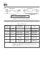
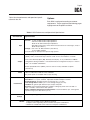
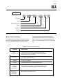
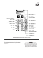
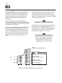
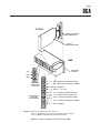
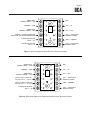
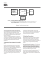
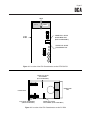
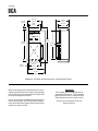
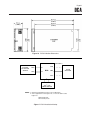
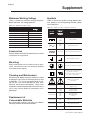
DCA
Direct Current Alarm
USER’S MANUAL
August 2012
No. 192-701-00 H
© 2012 by Moore Industries-International, Inc.
Table of Contents
Introduction
1
Description
1
Calibration
4
Installation
19
Maintenance
22
HR.
DELIVERY
8
4
United States/Canada
TOLL FREE
1-800-999-2900
United Kingdom
FREE PHONE
0800 525107
Australia
TOLL FREE
008 251928
Ask for the STAR Center
16650 Schoenborn Street
Sepulveda, California 91343, U.S.A.
Tel: (818) 894-7111 • Tlx: 65-1322
FAX: (818) 891-2816
CONNECT (MacNet): MIISEPULVEDA
1 Lloyds Court, Manor Royal, Crawley
W. Sussex RH10-2QU, United Kingdom
Tel: 0293 514488 • Tlx: 87667
FAX: 0293 536852
Moore Industries’ STAR* Center has a
wide variety of quality instrumentation
in stock and ready to ship.
• Signal Transmitters
• Temperature Transmitters
• P/I and I/P Converters
• Isolators and Converters
• Indicators and Displays
• Alarm Trips
• Integrators and Totalizers
• Power Transducers
• Instrument Power Supplies
• Racks, Rails and Enclosures
Most instruments can be customized
to meet your needs. Even then, you’ll
never have to wait more than a few days.
Moore Industries
3/18 Resolution Drive, Caringbah
New South Wales 2229, Australia
Tel: (02) 525-9177 • Tlx: 790-75914
FAX: (02) 525-7296
CENTER
*Support, Technical Assistance, and Repair (our Quick-Ship Facility)
DCA
Page 1
Introduction
Moore Industries’ Direct Current Alarm (DCA) is a
highly versatile, fully adjustable device that is factoryconfigured to accept either current or voltage input.
The unit’s internal relays are tripped when input
deviates from a customer-set “safe” range defined by
adjustable trip points. The DCA is ideal for use in an
alarm system, where it may be used to activate a
warning device, or to drive an analog indicator.
This manual provides a brief description of the DCA,
including its physical characteristics and options; a
table of performance and operating specifications; a
set of procedures for calibrating the unit; instructions
for installation, including physical mounting and
electrical connections; and finally, information on
basic maintenance and troubleshooting.
Notes, Cautions, and Warnings are included as a
means of identifying those practices that may present
unnecessary inconveniences (notes), result in damage to the unit (cautions), or cause injury (warnings).
bination of single, dual, high, low, fail-safe, or non-failsafe alarm relays. The following paragraphs describe
each of these configurations.
High Alarm/Low Alarm. A DCA configured as a high
alarm is tripped when the input increases, and
reaches a customer-set trip point. A low alarm unit is
tripped by a decreasing input that drops below a
customer-set trip point.
Figure 1 illustrates the concept.
Fail-safe/Non-fail-safe. A fail-safe unit’s relay is
energized when input is within a “safe” range, i.e. is
normal, or not in an alarm condition. When the input
goes into an alarm condition, reaching a trip point or
losing power, the relay of a fail-safe DCA is deenergized.
Conversely, a non-fail-safe unit’s relay is de-energized
when input is within the customer-specified “safe”
range, and is energized when the input reaches the
trip point setting.
Figure 1 also depicts the action of fail-safe relays.
Description
The DCA comes in either Moore Industries’ standard
(STD) or plug-in card (PC) housing.
The STD unit can be used with a variety of mounting
options, including those suitable for use with explosion-proof and NEMA enclosures.
PC-style DCA’s are designed for use with Moore
Industries’ multi-position card racks; the surface
mounted SMR, or the rack mounted RMR.
Both STD and PC DCA’s are available with either
single or dual alarm configurations. The relays used
are single-pole/double-throw, form C. There are a
number of input ranges and alternate relay ratings
available.
Operationally, the unit can be ordered with any com-
Controls and Indicators
Every type and configuration of DCA comes with
potentiometers (pots) to set the alarm trip points of
each installed relay. Additional pots for controlling
unit dead band are available as an option, and precision ten-turn vernier scales can be used instead of
the standard pots.
Trip point pots afford full 0- to 100-percent adjustability over the unit’s specified span.
Each installed relay is wired to a front panel LED,
which lights when the relay is energized. Depending
upon the type of relay ordered, i.e. fail-safe/non-failsafe, a lit LED can indicate either an “alarm” or a “nonalarm” input condition.
Table 1 summarizes the alarm type/LED status
options for the available types of DCA.
DCA
Page 2
HIGH-ALARM DCA
100 %
RESET
TRIP POINT
DEAD BAND
RESET
ANALOG
INPUT
VALUE
LOW-ALARM DCA
100 %
0%
ANALOG
INPUT
VALUE
DEAD BAND
TRIP POINT
0%
TIME
TIME
FAIL-SAFE RELAY ENERGIZED, LED ON
FAIL-SAFE RELAY DE-ENERGIZED, LED OFF
Figure 1. High - and Low-alarm Relay Configurations
Table 1. DCA Alarm Types
Model Number
Designator
This Unit is...
S
Single Alarm
-
-
Only one relay installed
D
Dual Alarm
-
-
Two relays are installed
H1
High Fail-Safe
Input increases, and exceeds
Trip Point. (See Note 2).
OFF in alarm
ON in Non-alarm
DE-energized in alarm
Energized in Non-alarm
H2
High NON-Fail-Safe
Input increases, and exceeds
Trip Point. (See Note 2).
ON in Alarm,
OFF in Non-alarm
Energized in Alarm,
DE-energized in Non-alarm
Input decreases, and drops
below Trip Point
(See Note 2)
OFF in alarm
ON in Non-alarm
DE-energized in alarm
Energized in Non-alarm
Input decreases, and drops
below Trip Point
(See Note 2)
ON in Alarm,
OFF in Non-alarm
Energized in Alarm,
DE-energized in Non-alarm
L1
Low Fail-Safe
L2
Low NON-Fail-Safe
This Unit signals an
“Alarm” condition when...
Its LED will be...
Relay(s)
NOTES: 1. Older DCA’s may use X1 for H1, X2 for H2, X3 for L1, and X4 for L2.
2. The “UPPER” and “LOWER” labeling on the DCA front panel is for reference only.
Configurations where “LOWER” terminals and pots pertain to the unit’s high alarm, for
example, are quite possible.
3. Relays in fail-safe alarms are DE-energized in the event of power loss to the unit.
DCA
Page 3
Table 2 lists the performance and operational specifications for the unit.
Options
Each DCA is configured according to customer
requirements. The paragraphs on the following pages
highlight some of the options available.
Table 2. DCA Performance and Operational Specifications
Characteristic
Input
Specifications
Current: 1-5 mA @ 200Ω nominal input impedance
4-20 mA @ 50Ω nominal input impedance
10-50 mA @ 20Ω nominal input impedance
Selectable Current (SC) comes with three load resistors for selecting1-5, 4-20, or
10-50 mA (See Note 1)
Voltage: 0.25-1.25 V @ 1MΩ, minimum (See Note 2)
1-5 V @ 1MΩ, minimum
Consult factory for dual input and special range options.
Factory-configured with one (Single DCA) or two (Dual DCA) single pole/double throw
(SPDT), form C, mechanical relays rated for 5 A @ 117 Vac non-inductive, or 28 Vdc.
Output
User selects Normally Open (NO), Normally Closed (NC), or any combination of NO/NC
configurations during installation. Fail-safe/Non-fail-safe configuration factory-set. Refer to
table 1 for available combinations.
Double pole/double throw (DPDT), form 2C and 7.5 A relays available as options.
(See Note 3)
Power
Performance
Environmental
Ratings
NOTES:
24 or 45 Vdc ±10%, 5 watts nominal
100, 117, 200, 220, or 240 Vac ±10%, 50/60 Hz
AC power inputs not available with PC-style housing
Repeatability: Trip point settings repeat within ±0.1% of span.
Dead Band: 1% of span, standard. Adjustable Dead Band Option available.
Alarm Response: 50 milliseconds for step change of 1% of span.
Line Voltage Effect: ±0.005% per 1% line voltage change (ac or dc).
Isolation: No galvanic path between input, output, and power.
Accuracy: Front panel potentiometers capable of setting trip points from 0 to 100% of
span. Lockable, scaled vernier dials optional.
Effect of Ambient Temperature on Performance: Less than ±0.018% per °C through the
specified range (Less than ±0.01% per °F)
Ambient Operating Temperature: –18 to 65 °C (0 to 150 °F)
1. One of the available resistors MUST be installed.
2. Requires extra engineering when used with some option combinations.
3. DPDT not available with some enclosures and option combinations.
DCA
Page 4
For a complete list of available options, and for
information on other housings, mounting hardware,
and enclosures, contact your Moore Industries Sales
Representative.
TX Option — Two-wire Transmitter Excitation. Rated
at 30 Vdc @ 25 mA.
7.5A Option — 7.5 amp Relay(s). Rated by CSA and
UL at 7.5 amps, 28 Vdc or 120 Vac.
AD Option — Externally-adjustable Dead Band.
Front panel potentiometers vary dead band 1- to 20percent of span (nominal), 1- to 50-percent of span
(AD50), or 1- to 100-percent (AD100) of span. (AD
Option not available with some option combinations).
Model/Serial Number. Moore Industries uses a
system of unit model and serial numbers to keep
track of factory configuration and options for each
DCA shipped and serviced.
AR Option — Response Time Delay. Set by the
factory for output delays of 1 to 5, 10, 15, 20, 25, or
30 seconds, according to customer specification.
The example outlines the significance of each field of
information in a typical DCA model number. Refer to
table 1 for an explanation of the relay configuration
codes used.
DA Option — Deviation Input. Unit signals alarm
condition when the difference between two inputs
exceeds adjustable percent of full span. Requires DI
Option or 2X input. (Not available with some option
combinations.)
DI Option — Dual Input. Configures dual-alarm DCA
to operate as two, single-alarm units. Standard DI
unit provides a high alarm for one input and a low
alarm for the other. (DI Option not available with
some option combinations).
DPDT Option — Double Pole, Double Throw/Form 2C
Relays. Contact 5 amps at 28 Vdc, or 117 Vac noninductive. (DPDT Option not available with some
option combinations).
If service information or assistance for a DCA is
needed, make a note of the unit’s model and serial
number before contacting Moore Industries’ Customer
Service Department. Our highly skilled technicians
will be happy to assist you.
STD units’ serial and model numbers are located on
an L-shaped metal tag at the top of the connection
terminal strips. On PC DCA’s, the numbers are
located on an adhesive label affixed to the side of the
front panel.
Calibration
HS Option — Hermetically Sealed Relays. Rated 1A
@ 117 Vac non-inductive, 2A @ 28 Vdc. Meets
requirements for installation in Class I, Division 2
locations.
Every DCA shipped from the factory is manufactured
and tested according to Moore Industries’ exacting
standards for product quality. A bench check of basic
unit operations is recommended, however, in order to
identify any damage to the unit that may have occurred during shipping. This also allows the user to
effect operational adjustments to trip point settings
and unit dead band, if available.
MR Option — Manual Reset. External reset push
button for single- and dual-alarm units. In place of
dead band, MR-equipped units return to normal only
when the process input returns to non-alarm state and
the external reset push button is pressed.
It is recommended that the procedures in this section
be carried out at a technician’s bench or in a similar
lab environment. This is the safest means of making
adjustments to trip point values; isolated from the
intended DCA application.
TT Option — Lockable Vernier Dial. Front panel,
multiturn potentiometers for setting and locking trip
points. Includes front panel ZERO potentiometer for
appropriate offsets.
The calibration of the DCA consists basically of
setting trip points and dead bands based on the
resistance across the unit contact-closure terminals
as measured by an ohmmeter. With relay contacts
closed, resistance is negligible. With relay contacts
open, resistance is infinite.
FU Option — Power Fuse. 400 mA rated fuse on
PC-style unit. Use of the FU Option with the STD
housing requires special engineering.
DCA
Page 5
EXAMPLE
DCA / 4-20MA / DH1L1 / 117AC / -AD [STD]
Unit Type
Input
Relay Configuration
Power
Options(s)
Housing
Basic Calibration Setup
The equipment listed in table 3 is needed for calibrating the DCA. These items are not supplied with the
unit, but should be available in most testing labs.
Be sure to use calibrated test equipment when
performing the bench check and calibration of the
DCA. The use of inaccurate test equipment may
result in unreliable settings for the unit’s trip point(s),
etc.
Table 3. DCA Calibration Equipment
Equipment
VoltageVoltage
or
Current Source or
Current Source
Power Source
Ohmmeter
Screwdriver
Wire Jumpers
(required for
AR-equipped
DCA’s ONLY)
Extender Card
(optional for use
with PC-style
DCA’s ONLY)
Specifications
Calibrated, adjustable unit, capable of output at discrete levels in the
appropriate range, with the rated impedance for the unit being calibrated.
EDC Models MV105, MV155, or equivalent.
AC or dc power input appropriate for the type of DCA being calibrated.
Refer to table 2, earlier in this manual.
Accuracy of ±1%, minimum.
Slotted-tip with head width no greater than 2.54 mm (0.01 in).
Temporary jumper wiring suitable for shorting AR Option diodes so that the
alarm delay may be defeated while adjusting the unit’s trip point settings.
Moore Industries’ part number 350-513-00.
DCA
Page 6
Setup for the STD DCA. Figure 2 shows the labeling
used on the front panel of the STD DCA. Figure 3
shows the terminals on a unit equipped with DPDT
relays.
DCA
To access the connection terminals for a DCA in the
basic extruded housing (STD, AB, etc.), use a screw
driver to remove the securing screw from the protective plastic cover on the unit front panel. With the
screw removed, the cover can be removed by hand,
revealing the terminals and the labels depicted in the
illustrations in this manual.
DC CURRENT
ALARM
UPPER
LOWER
ZERO
UPPER RELAY NORMALLY
OPEN — UNO
COMMON — COM
UPPER RELAY NORMALLY
CLOSED — UNC
ACC — –DC
AC — +DC
GND
UPPER
DEADBAND
LOWER
LNO —
LOWER RELAY NORMALLY OPEN
COM — COMMON
LNC —
LOWER RELAY NORMALLY CLOSED
OPTION — +TX FOR TRANSMITTER
EXCITATION, +REF FOR DEVIATION ALARM
+IN — CURRENT OR VOLTAGE +INPUT
-IN — CURRENT OR VOLTAGE -INPUT
NOTES: 1. Each unit is factory-configured for ac or dc power.
2. Each unit is factory-configured for specific current or voltage input.
Figure 2. STD DCA Terminal Locations
DCA
Page 7
DCA
DC CURRENT
ALARM
UPPER
LOWER
UNO2 — UPPER RELAY #2
NORMALLY OPEN
COM — COMMON
ZERO
UPPER RELAY #1 NORMALLY
OPEN — UNO1
COMMON — COM
UPPER RELAY #1 NORMALLY
CLOSED — UNC1
UNO2 — UPPER RELAY
#2 NORMALLY CLOSED
UPPER
LNO1 — LOWER RELAY #1
NORMALLY OPEN
DEADBAND
LOWER
ACC — –DC
COM — COMMON
LNC1 — LOWER RELAY #1
NORMALLY CLOSED
LNO2 — LOWER RELAY #2
NORMALLY OPEN
COM — COMMON
AC — +DC
LNC2 — LOWER RELAY #2
NORMALLY CLOSED
GND
OPTION — +TX FOR
TRANSMITTER EXCITATION,
+REF FOR DEVIATION ALARM
+IN — CURRENT
OR VOLTAGE +INPUT
-IN — CURRENT
OR VOLTAGE -INPUT
Figure 3. STD DCA w/DPDT Option Terminal Locations
Figure 4 shows the labeling for a STD DCA equipped
with the DI Option. Note that both inputs share the “–
IN” terminal.
WARNING
To guard against accidental electric
shock, it is recommended that the protective plastic cover be re-installed over the
terminal strip of the STD DCA before
applying power to the calibration setup.
DCA
Page 8
Setup for the PC DCA. There are two methods of
carrying out the calibration setup connections on the
PC DCA. Most often the unit is installed in one of
Moore Industries’ card racks, and the calibration
equipment is connected to the appropriate rack
terminal strip.
Figure 5 illustrates the PC DCA installed in the
surface mounted card rack, the SMR. Figure 6 shows
the terminal strip labeling for rack units when the DCA
is equipped with the DI Option.
As an alternative to using the card rack, individual PC
DCA’s can be checked with Moore Industries’ Process Power Supply, the PPS, equipped with its CT
Option. The CT-equipped PPS accepts the connection strip of the PC DCA in a connector built into its
side panel. The PPS front panel provides access to
terminal strips similar to those used on the card
racks.
Whether using the card rack or the PPS/CT combination, note that the DC power connections are not
made directly to the unit, but to the terminal strips of
either the card rack or the PPS. DC power is supplied
to the DCA at its pins 8 and 9
NOTE
The “UPPER” and “LOWER” labeling used
on the DCA is for reference purposes only.
The trip point pots allow for adjustments through 100percent of span. It is therefore possible for the
connections to the “LOWER” labeled alarm section to
be configured as a “high alarm”, and the “UPPER”
section to be configured as a “low alarm”.
NOTE
The LED’s DO NOT always indicate an
alarm condition; rather, they light to show
that their complimentary relay is energized. It is possible for a DCA to be
configured such that the LED’s are lit
when input is in a “non-alarm” state.
LNO —
LOWER RELAY NORMALLY OPEN
COM — COMMON
LNC —
LOWER RELAY NORMALLY CLOSED
ACC — –DC
+IN UP — UPPER
CURRENT/VOLTAGE +INPUT
AC — +DC
+IN LOW — LOWER
CURRENT/VOLTAGE +INPUT
GND
-IN — NEGATIVE INPUT
Figure 4. STD DCA with DI Option Terminal Locations
DCA
Page 9
1
PC DC A
INTERNAL RACK SLOT
AND CONNECTOR
15
PC DCA
COMPONENT SIDE
SMR
MOUNTING
FLANGES
-DC
+DC
GND
ONE POWER
CONNECTION
PER RACK
ONE TERMINAL
STRIP PER
CARD POSITION
7
LNO - LOWER RELAY NORMALLY OPEN
4
LNC - LOWER RELAY NORMALLY CLOSED
2
COM - COMMON
5
OPTION — +TX, +REF
3
+IN — CURRENT OR VOLTAGE + INPUT
10
-IN — CURRENT OR VOLTAGE - INPUT
13
UNO - UPPER RELAY NORMALLY OPEN
1
UNC - UPPER RELAY NORMALLY CLOSED
15
COM - COMMON
NOTES : 1. Rack is shown with protective covers removed.
2. Power is not applied to each PC connector strip, but to the rack terminal strip.
Power is supplied to the PC DCA at its pins 8 (DC) and 9 (–DC).
Figure 5. Terminals Labeling, the PC DCA in the SMR
DCA
Page 10
ONE TERMINAL
STRIP PER
CARD POSITION
7
LNO - LOWER RELAY NORMALLY OPEN
4
LNC - LOWER RELAY NORMALLY CLOSED
2
COM - COMMON
5
+IN — UPPER ALARM CURENT OR VOLTAGE +INPUT
3
+IN — LOWER ALARM CURRENT OR VOLTAGE + INPUT
10
-IN — CURRENT OR VOLTAGE - INPUT
13
UNO - UPPER RELAY NORMALLY OPEN
1
UNC - UPPER RELAY NORMALLY CLOSED
15
COM - COMMON
Figure 6. PC DCA with DI Option Terminal Locations
Setup of DCA’s in Explosion-proof Enclosures.
The DCA in an explosion-proof enclosure (EX) incorporates a modification of the STD housing where
the connection terminals are replaced with pins on the
unit bottom panel. These pins are inserted in a
terminal block permanently mounted inside the base
of the explosion-proof enclosure.
To effect the calibration connections, unscrew the top
of the enclosure and pull the DCA up and out of the
enclosure base, exposing the terminal block. Figure 7
shows the block and its labeling. Figure 8 shows the
labeling used for units equipped with the DI Option.
Use the appropriate terminal locations figure to
connect the calibration equipment to the terminal
block in the enclosure base. Then re-connect the
DCA by aligning the pins on the bottom of the unit
housing with the holes in the terminal block. Press
down until the unit is seated firmly in the enclosure
base.
CAUTION
The EX DCA housing fits into the terminal
block in its correct orientation only. Note
the position of the connection “key”.
Attempting to “force” the unit in when the
pins are not aligned with the correct holes
will bend the pins.
Basic Calibration Hookup. Use the terminal locations figure that is appropriate for the type of DCA
being checked, and connect the equipment described
in the calibration equipment table as shown in the
calibration hookup diagram, figure 9.
Set all low alarm pots fully counterclockwise. DCA
pots are equipped with slip clutches to prevent
damage in the event of over-turning. A slight change
in torque may be felt when a wiper stop is reached. If
unable to sense the stop, set pot 15 turns counterclockwise.
DCA
Page 11
7
6
GND
COMMON — COM
8
5
+DC — AC
LOWER RELAY
NORMALLY CLOSED — LNC
9
4
–DC — ACC
OPTION — +TX FOR TRANSMITTER
EXCITATION, +REF FOR DEVIATION ALARM
10
3
UNC — UPPER RELAY
NORMALLY CLOSED
CURRENT OR VOLTAGE
+INPUT — +IN
11
2
COM — COMMON
CURRENT OR VOLTAGE
-INPUT — -IN
12
1
UNO — UPPER RELAY
NORMALLY OPEN
`
LOWER RELAY
NORMALLY OPEN — LNO
Figure 7. DCA in an Explosion-proof Enclosure Terminal Locations
LOWER RELAY
NORMALLY OPEN — LNO
7
6
GND
COMMON — COM
8
5
+DC — AC
LOWER RELAY
NORMALLY CLOSED — LNC
9
4
–DC — ACC
UPPER ALARM CURRENT OR
VOLTAGE +INPUT — +IN UPP
10
3
UNC — UPPER RELAY
NORMALLY CLOSED
LOWER ALARM CURRENT OR
VOLTAGE -INPUT — +IN LOW
11
2
COM — COMMON
CURRENT OR VOLTAGE
-INPUT — -IN
12
1
UNO — UPPER RELAY
NORMALLY OPEN
Figure 8. DCA with DI Option in an Explosion-proof Enclosure Terminal Locations
DCA
Page 12
APPROPRIATE
+
CALIBRATED
ADJUSTABLE
CURRENT
OR
VOLTAGE SOURCE –
+IN
XNO#
DCA
COM
OHMMETER
–IN
XNC#
+
–
(SEE NOTE 1)
(SEE NOTE 3)
+
–
VDC or VAC
POWER SOURCE
(SEE NOTE 2)
NOTES: 1. Check unit model number for appropiate input source.
2. Check unit model number for appropriate power source.
3. X = U for upper or L for lower. Connect ohmmeter to "NO" for terminals of normally open relay, to
NC for normally closed. “#” is used in DPDT-equipped units to refer to the number of the alarm
output, as in UNO1 and LNC2.
Figure 9. The DCA Calibration Setup
Special Considerations for AR-equipped DCA’s.
Units equipped with the AR Option are factory-set for
specific alarm delay times ranging from 1 to 30
seconds (refer to Options listing). The AR is set and
fully calibrated according to customer requirements
before unit shipment.
The delay in an AR-equipped DCA’s transition from
normal to alarm condition makes the calibration of trip
points difficult, and a temporary disabling of the option
is therefore recommended during the calibration
procedures.
To defeat the AR Option, diodes on PC1 of the DCA
must be shorted. There is a diode for each installed
relay.
DCA’s in the STD housing must be partially disassembled to access the AR diode(s). See figure10.
Figures 11 and 12 show the location of the diodes on
the various types of AR-equipped DCA.
Access to the AR diode(s) on PC-style DCA’s may be
difficult if the unit being calibrated is already installed
in its rack. Moore Industries offers an Extender Card
accessory for calibrating units under these circumstances.
The Extender, P/N 350-513-00, mates with the
connector on the PC-style DCA, and then plugs in to
the rack so that the unit is clear of the rack front,
allowing for access to the diode(s).
Calibration Procedures
Before beginning the actual calibration of the DCA,
check the unit’s model number to verify that the
correct power supply and input simulator is being
used. Make sure that the appropriate connections are
made as shown in the figures of the preceding
section.
Using the Calibration Procedures. The Calibration
Procedures section is divided into subsections that
describe first low alarm, then high alarm trip point
setting. The procedure for calibrating the DCA dead
band, for units equipped with the AD Option, should
be conducted after the trip points are set.
If the DCA to be calibrated is equipped with the TT
Option, skip to and complete the procedure in the
section entitled “Calibrating DCA’s Equipped with the
TT Option”.
DCA
Page 13
Figure 10. STD DCA Disassembly
RELAY
FOR DUAL-ALARM
PC DCA SHORT AROUND
THESE DIODES
FRONT PANEL
RELAY
CONNECTOR
PINS
FOR SINGLE-ALARM
PC DCA SHORT AROUND
THIS DIODE
Figure 11. AR Option Diodes on the PC DCA
DCA
Page 14
LED’S
RELAY
RELAY
PC 2
FOR SINGLE ALARM
STD DCA SHORT
AROUND THIS DIODE
PC 1
FOR DUAL ALARM STD
DCA SHORT AROUND
THESE DIODES
Figure 12. AR Option Diodes on PC1 of the STD DCA
Setting Low-Alarm Trip Points. Remember that the
“UPPER” and “LOWER” labeling on the DCA is for
reference purposes only. The DCA can be ordered
without low alarms, as in a “high/high” configuration.
Dual alarm units can be ordered with either one or
both relays configured as low alarms, and DPDTequipped DCA’s may be configured with any combination of high/low alarms.
Refer to the unit’s model number to determine the
alarm configuration, and perform the following procedure for each installed low alarm.
3. Apply 100% of application’s input span (current or
voltage, as appropriate) to DCA.
If low alarm is configured as fail-safe, L1 in model
number, verify that appropriate LED for that alarm
is lit. LED for non-fail-safe low alarm, L2 in model
number, will not be lit.
4. Note ohmmeter reading.
1. Check model number to verify correct power
input, and apply 117 or 240 Vac; 24 or 45 Vdc, as
appropriate.
In a low alarm, 100% input is a non-alarm condition. If connected to XNO and COM terminals (X
= U or L, UPP or LOW; NO = normally open),
Resistance across the terminals in a fail-safe
alarm is zero. In a non-fail-safe alarm resistance will be near infinite.
2. Make sure that ohmmeter in calibration setup is
connected to appropriate -NO or -NC terminals, as
desired.
If connected to XNC and COM terminals, resistance is infinite in fail-safe, zero in non-fail-safe
alarms.
DCA
Page 15
5. Set input to desired low alarm trip point level.
6. Turn appropriate low alarm adjustment pot (may
be labeled “UPPER” or “LOWER”) slowly clockwise. Observe LED and ohmmeter, and stop
turning at exact point where relay changes state.
Vary pot setting slightly above and below trip
point to “zero in” on exact setting.
If low alarm is configured as fail-safe, L1 in model
number, verify that appropriate LED for low alarm
is not lit. LED for non-fail-safe low alarm, L2 in
model number, will be lit.
7. Verify desired setting by varying input above and
below trip point level (from step 6) and observing
both LED and ohmmeter to confirm change of
relay state at, and below trip point setting.
NOTE
Units equipped with any Manual Reset
Option have external push buttons that
must be pressed to reset the relays once
they have been tripped.
Setting High-Alarm Trip Points. Remember that the
“UPPER” and “LOWER” labeling on the DCA is for
reference purposes only. The DCA can be ordered
without high alarms, as in a “low/low” configuration.
Dual alarm units, on the other hand, can be ordered
with either one or both relays configured as high
alarms.
Refer to the unit’s model number to determine the
alarm configuration, and perform the following procedure for each installed high alarm.
1. Check model number to verify correct power
input, and apply 117 or 240 Vac; 24 or 45 Vdc, as
appropriate.
2. Make sure that ohmmeter in calibration setup is
connected to appropriate -NO or -NC terminals, as
desired.
3. Apply 0% of application’s input span (current or
voltage, as appropriate) to DCA.
If high alarm is configured as fail-safe, H1 in
model number, verify that appropriate LED for that
alarm is lit. LED for non-fail-safe low alarm, H2 in
model number, will not be lit.
4. Note ohmmeter reading.
In a high alarm, 0% input is a non-alarm condition. If connected to XNO and COM terminals
(X = U or L, UPP or LOW; NO = normally open),
Resistance across the terminals in a fail-safe
alarm is zero. In a non-fail-safe alarm resistance will be near infinite.
If connected to XNC and COM terminals, resistance is infinite in fail-safe, zero in non-fail-safe
alarms.
5. Set input to desired high alarm trip point level.
6. Turn appropriate high alarm adjustment pot (may
be labeled “UPPER” or “LOWER”) slowly clockwise. Observe LED and ohmmeter, and stop
turning at exact point where relay changes state.
Vary pot setting slightly above and below trip
point to “zero in” on exact setting.
If high alarm is configured as fail-safe, H1 in
model number, verify that appropriate LED for that
alarm is not lit. LED for non-fail-safe high alarm,
H2 in model number, will be lit.
7. Verify desired setting by varying input above and
below trip point level (from step 6) and observing
both LED and ohmmeter to confirm change of
relay state at, or above trip point setting.
NOTE
Units equipped with any Manual Reset
Option have external push buttons that
must be pressed to reset the relays once
they have been tripped.
DCA
Page 16
Setting the Dead Band. See figure 1 for a graphic
representation of the DCA dead band. The dead band
may be thought of as an “area” around a trip point in
which the alarm will not reset.
In a scenario using a high-alarm DCA as an example,
the unit will signal an alarm at its trip point, and will
continue to signal an alarm as long as the input is
above that point.
Without an adjustable dead band, the relay will reset
when the input drops below the trip point. When
equipped with the AD Option, however, no reset will
occur until the input continues to drop to the dead
band setting, presumably some percentage of span
below the trip point.
To set the DCA dead band:
1. Make sure dead band pots are turned fully
counterclockwise. Set trip points for installed
alarms as described in preceding section. Connect ohmmeter to UPPER alarm section to set
UPPER dead band, or to LOWER section for
setting LOWER dead band.
2. Apply input at the dead band setting level.
Typically, this will be lower than trip point for high
alarms, or higher than trip point for low alarms.
3. Turn appropriate dead band pot slowly clockwise,
observing LED and ohmmeter.
4. Set pot (stop turning) at exact point at which relay
changes state.
5. Verify desired setting by varying input above and
below trip point, observing both LED and ohmmeter to confirm appropriate change of relay state.
Unit will “trip” at trip point setting, and will not
reset until input returns past dead band setting.
The DCA dead band can be expressed as a percentage of the unit’s factory-configured span.
For Example:
A single, high-alarm DCA rated for 4-20 mA input is
required to have a 25% dead band around its 14 mA
trip point setting. To calculate the input level needed
to set the desired dead band, subtract 25% of 16 mA
(span) from 14 mA:
Trip point setting in mA = 14
– 25% of input span in mA = 16(0.25)
14 – 4 = 10
The result, 10 mA, is the level of input to be applied in
step 2. The DCA in this example will signal an alarm
condition when the input reaches or exceeds 14 mA,
but will not reset until the input drops below 10 mA.
Calibrating TT-equipped Units. Lockable, multiturn
trip point adjustment pots on the front panel of each
TT-equipped DCA are set at the factory so that “0.00”
on the dial is equal to 0% of the application’s rated
input span. “10.00” is equal to 100% of span. The
accuracy of these settings is ±0.5% of the rated
span.
Calibration of DCA’s with this option consists of two
procedures. First, the internal, Full-Scale Adjust
(FSA) potentiometer(s) must be set (this involves
some disassembly of the STD DCA). Then, the unit
zero, trip points, and dead band (if so-equipped), must
be set.
Figure 13 shows the location of the STD DCA FSA
potentiometers. Figure 14 shows the location of the
pots on the PC-style unit. Refer to figure 10 when
disassembling the unit in STD housing, and refer to
figures 13 or 14 while executing the procedure.
NOTE
The following procedure assumes that the
DCA being calibrated has its “UPPER”
alarm section configured as a high alarm,
and its “LOWER” alarm section configured
as a low alarm. If this is not the case for
your DCA, interchange references to
“UPPER” and “LOWER”, as appropriate.
DCA
Page 17
LED’S
RELAY
RELAY
LOWER FULL-SCALE
ADJUSTMENT POT
(DUAL ALARMS ONLY)
PC 1
UPPER FULL-SCALE
ADJUSTMENT POT
Figure 13. Location of the FSA Potentiometers on the STD DCA PC1
UPPER FULL-SCALE
ADJUSTMENT
(DUAL ALARM ONLY)
CONNECTOR
PINS
FRONT PANEL
FULL-SCALE ADJUSTMENT
(SINGLE ALARM ONLY)
LOWER FULL-SCALE
ADJUSTMENT (DUAL ALARM ONLY)
Figure 14. Location of the FSA Potentiometers on the PC DCA
DCA
Page 18
1. With the hookup described in the Calibration
Setup Section complete, disable AR Option as
described in section titled “Calibrating ARequipped DCA’s”. Connect ohmmeter to “UPPER” alarm terminals first.
2. Verify that all pots are set fully counterclockwise,
to 0.00.
NOTE
Steps 3 through 10 apply to high alarms.
Skip to step 11 to calibrate the ten-turn
dials on low alarms.
3. Apply 0% of appropriate input from application.
Refer to unit’s model number and specifications
listing in table 2.
4. Turn ZERO pot clockwise until both “UPPER” and
“LOWER” alarms trip.
5. Apply 100% input to setup.
6. Turn “UPPER” and “LOWER” pots clockwise to
10.0 setting.
7. Turn internal FSA pots fully counterclockwise.
High alarm will change state. Disregard low alarm
at this time.
8. Turn FSA pot for “UPPER” alarm slowly clockwise, observing ohmmeter and appropriate front
panel LED.
9. Set FSA pot (stop turning) at exact point at which
high alarm is tripped. If high alarm is configured
as fail-safe, H1 in the unit model number, verify
that appropriate LED for high alarm is not lit. The
LED for a non-fail-safe high alarm, H2 in the
model number, will be lit.
10. Disconnect ohmmeter, and reconnect it to
“LOWER” alarm section of DCA.
11. With input at 100%, and ohmmeter connected to
“LOWER” alarm section of unit, turn appropriate
“LOWER” FSA pot fully clockwise. Note that low
alarm trips.
12. Turn “LOWER” FSA pot slowly clockwise, observing ohmmeter and appropriate front panel LED.
13. Set FSA pot (stop turning) at exact point at which
low alarm is tripped.
If low alarm is configured as fail-safe, L1 in the
unit model number, verify that appropriate LED for
low alarm is not lit.
The LED for a non-fail-safe low alarm, L2 in the
model number, will be lit.
14. Alternate the input between its rated 0 and 100%
level, verifying the setting of the unit’s front panel
pots (0.00 at 0% input, 10.00 at 100% input).
Readjust both FSA pots as necessary.
Calibrating DA -equipped Units. If ordered, the
Deviation Alarm Option allows the user to set alarm
trip points based on the difference between two
inputs. This difference is expressed as a percentage
of total input span, and unit relays are “tripped”
whenever process input varies, more than (high alarm)
or less than (low alarm) the set percentage.
To calibrate DA-equipped DCA’s, a second input
source will be needed. Refer to table 3, and use two
of the appropriate sources as specified.
Refer to figures 2 through 8 as appropriate, to determine which of the unit terminals is used for the
second, reference input connection.
Finally, refer to the setup shown in figure 9, and add
the connection for the second input source as follows:
“+REF” is used for positive reference input, and the
negative connection for both inputs is common, the “–
IN”.
To calibrate DA-equipped DCA’s:
1. With setup complete as described in preceding
paragraph, and all pots set fully counterclockwise,
determine percentage of rated input span that is
to serve as difference between reference input
and input #2.
2. Set reference input to 50% of rated span.
DCA
Page 19
3. Set input #2 to desired percentage above or below
reference.
Installation
4. Set trip points as appropriate, using UNC pot for
UPPER normally closed alarm, UNO pot for
UPPER normally open; LNC for LOWER normally
closed, and LNO for LOWER normally open.
Base settings on input #2.
Installing the DCA is typically accomplished by
physically mounting the unit, then effecting the
electrical connections.
Units factory-configured as high alarms will “trip”
when input #2 exceeds the desired difference.
Low alarms “trip” when input #2 falls below
desired difference.
For Example:
A DA-equipped DCA is rated for two, 4-20 mA inputs
(“2X” in the model number). The application calls for
an alarm condition when input #2 varies more than
25% of span from the reference input.
Span = 16 mA
25% of 16 = 4 mA
The reference input is set to 50% of rated span, or 12
mA. Input #2 is set 25% higher, 16 mA.
The trip point pots are turned clockwise until relays
change state.
Regardless of how the reference input is varied, from
4 to 20 mA, as long as input #2 is likewise varied at a
50% offset, the alarms are not “tripped”.
However, if the reference is at 12 mA and input #2 is
at 20 mA, the high-alarm relay will indicate an alarm
condition. Likewise, if the reference is at 12 mA and
input #2 is at 14 mA, the low-alarm relay will indicate
an alarm.
Mounting
Figures 15 and 16, respectively, show the outline
dimensions of the DCA in the STD and the PC
housing styles. The drawing of the STD housing
includes the dimensions of the U-bracket, typically
included with that type of DCA, and also of the side
housing used for DCA’s equipped with the DPDT
option.
Always try to install the DCA in an area relatively free
of dust, excessive moisture, or corrosives.
Contact your Moore Industries Sales Representative
for information on other types of DCA housings,
enclosures, and mounting hardware.
Making Electrical Connections
Figure 17 illustrates the installation hookup for the
unit. Refer to the terminal location figures in the
Calibration Section when making the electrical
connections associated with installing the DCA.
Though there is no special wiring required for standard
connections, the use of shielded, twisted wiring is
recommended for all low-level signals, or where
connecting leads are run close to other services such
as power wiring. Ground the shield wire as close to
the DCA as possible in the installation.
DCA
Page 20
9.5 mm
(0.38 in)
76.2 mm
(3.00 in)
76.2 mm
(3.00 in)
66 mm
(2.60 in)
63.5 mm
(2.50 in)
DCA
DC CURRENT
ALARM
UPPER
LOWER
ZERO
167 mm
(6.56 in)
186 mm
(7.31 in)
154 mm
(6.08 in)
COVER
6.4 mm
(0.25 in)
63.3 mm
(2.49 in)
95 mm
(3.75 in)
102 mm
(4.00 in)
Figure 15. STD DCA Outline Dimensions, Including DPDT Option
When making the electrical connections for units in
explosion-proof enclosures, route the wiring through
the conduit hubs in the enclosure with enough slack
to reach the appropriate terminal.
Units in oil- or water-tight NEMA enclosures require
the use of Myer Scru-Tite (or equivalent) fittings to
maintain the enclosure integrity when routing wiring
conduit to or from the DCA.
WARNINGS
Do not apply power to the DCA until all
connections are secure. The uncovered
power input terminals of ac-powered STD
DCA’s present an electric shock hazard.
Always turn off the power to the unit
before servicing.
DCA
Page 21
Figure 16. PC DCA Outline Dimensions
(SEE NOTE 2)
CURRENT
OR VOLTAGE
SOURCE
+OUT
–OUT
XNO
+IN
–IN
DCA
COM
ALARM
INDICATOR
XNC
+
–
+
VDC–or VAC
POWER SOURCE
(SEE NOTE 1)
NOTES: 1. Check the model number for power source requirements.
2. X=U for upper alarm section, high or low, or L for lower alarm section,
high or low.
NO=normally open
NC=normally closed
Figure 17. DCA Installation Hookup
DCA
Page 22
PC DCA’s slide into card slots in Moore Industries’
nineteen-inch card racks, the SMR and RMR. Each
DCA has individual contacts on its rear edge that
mate with an edge connector at the back of the rack.
Maintenance
Once the DCA is properly calibrated and installed, it
will operate indefinitely. No further adjustments
should be necessary, unless the unit is moved, or the
process input changes.
It is recommended that the unit terminals be checked
periodically for signs of oxidation or looseness.
If a problem develops with the performance of the
DCA, remove the unit from service and recalibrate.
Refer to the Calibration Section of this manual for
instructions.
Any units found to be performing below specifications
after a recalibration should be returned to the factory
immediately. Instructions for unit return can be found
on the back cover of this manual.
Customers may also contact the friendly folks in
Moore Industries’ Customer Service Department at 1800-999-2900 for technical assistance.
DCA
Direct Current Alarm
SUPPLEMENT
August 1992
Purpose
This supplement is being distributed to users of
Moore Industries' Direct Current Alarm (DCA) to inform them of corrections/additions to the current
manual since its release date. These changes will
be incorporated in the manual during its next revision.
Corrections
The wording of the second paragraph of step 4 of the
"Setting Low-Alarm Trip Points" (page 14) and "Setting High-Alarm Trip Points" (page 15) calibration
procedures should read:
In a low alarm, 100% input is a non-alarm condition. If connected to XNO and COM terminals (X =
U or L (upper or lower); NO = normally open). Resistance across these terminals in a fail-safe alarm is
near zero. In a non-fail-safe alarm, resistance will be
infinite.
To Manual No. 192-701-00 G
It is important to understand that the "normal" condition of these relays refers to the non-energized or
de-energized state of the relay. This means that the
terminal labeling is true when power is removed from
the unit or when the unit is operating and the LED is
NOT lit. Since each LED illuminates only while the
corresponding relay is energized, when the LED is
not lit its corresponding relay is de-energized.
So, regardless if the DCA is configured for fail-safe
or non-fail-safe operation, each relay's normally-open
or normally-closed contact states are true as labeled
only when the relay is de-energized.
Addition
The hookup connections for units configured with the
TX Opton are not provided in the Installation Section
of the user's manual. For units with the TX Option,
connect the positive output lead from the external
equipment to the +TX terminal on the DCA, and connect the minus output lead from the external equipment to the +IN terminal of the DCA. Do not use the
-IN when installing DCA's with the TX Option.
Page S-1
Supplement
Low Voltage Directive
Equipment Ratings
The following guidelines must be followed in order to
comply with EN 61010-1 (Low Voltage Directive).
These items affect the AC versions of the following
products: DCA, DPS-240, DPS1200, ECA, ECS,
ECT, FCA, FDT, IST, PIT-4W, PWT, RBA, SCT,
SMP, SPA-CE. If these products are to be used in
a non-CE environment, this supplement may
be disregarded.
Moore Industries transmitters do not generate hazardous voltages. They measure voltage or current
inputs, and generate low voltages and currents
(<42Vdc and <50mAdc). Products connected to
Moore Industries transmitters should be designed to
receive these inputs.
WARNING:
If this unit is used in a manner not specified
by Moore Industries, the protection provided
by the equipment may
be impaired.
Moore Industries alarms do not generate any hazardous voltages. Alarm contacts are wired in series
with power sources and their intended loads.
The correct load should be selected for the
power source.
Supply Wiring
All power connections shall be made with 14 or 16
AWG (.083mm or .064mm) wire.
Switches and Circuit Breakers
A switch or circuit breaker must be wired in series
with the AC power conductors. This switch or circuit
breaker must be located within three meters of
the unit.
WARNING:
Terminals on this unit may be connected to
hazardous voltages. Before making ANY
connections to this unit, ALL hazardous
voltages must be de-energized.
The circuit breaker or switch will only remove power
to the unit, hazardous voltages may still be connected to other terminals on the unit.
Installation Category
All terminals are rated CAT II, except for terminals
with the -RF option.
These terminals are
rated CAT I.
The Interface Solution Experts
The end of each conductor should be stripped no
more than 8mm. The end of the stripped wire should
be tinned with solder or inserted into a ferrule and
crimped before being placed into a terminal block.
Conductors connected to screw type connections
must have a ring or spade lug crimped on the end of
the wire.
Protective Earth Conductor
The Protective Earth Conductor shall be of equal or
larger size wire than the other two power conductors.
The Protective Earth Conductor shall be the first
conductor connected to the unit when the unit is being wired. It shall be the last conductor removed
when the unit is being un-wired.
Page S-2
Supplement
Maximum Working Voltage
Symbols
Table 1-s shows the maximum working voltage for
Moore Industries’ low voltage products.
Table 2-s shows the symbols used on Moore Industries’ products, the corresponding IEC/ISO symbol,
and its definition.
Table 1-s. Maximum Working Voltage
Input Type
Maximum Working
Voltage
Millivolt, Thermocouple, and RTD 48Vdc
DC Voltage Inputs 48Vdc
Table 2-s. Symbols on Moore Industries’ Products
IEC/ISO
Symbol
AC Voltage Inputs 264Vac
Analog Outputs 48Vdc
Relay Contacts 264Vac
Symbol on
Moore
Industries
Product
Definition
+PS
– PS
DCC
Direct Current
AC
ACC
Alternating Current
AC or DC
Direct and Alternating Current
117Vac Power Terminals 129Vac
240Vac Power Terminals 264Vac
Contact Closure Outputs 30Vdc
Accessories
Contact Moore Industries for information on suitable
accessories for our products.
GND
Protected Earth Terminal
Mounting
When mounting the unit or installing it into an application, ensure that the unit can be easily removed
for maintenance or repairs.
Protective Conductor Terminal
Equipment protected throughout
by double insulation or
reinforced insulation (equivalent
to Class II of IEC 536)
Cleaning and Maintenance
Maintenance on Moore Industries’ products is limited
to keeping the unit clean and the wire terminals free
of oxidation. This is best accomplished by installing the unit in an area protected from dust, heat,
moisture, and corrosive atmospheres. Yearly visual
inspections should be performed to ensure that the
unit is clean and the electrical connections are in
good repair.
Caution (See manual for
information)
Not Specified
+IN
– IN
Positive Input
Negative Input
Not Specified
+OUT
– OUT
Positive Output
Negative Output
Not Specified
NO
NC
CM
Normally Open
Normally Closed
Common
Replacement of
Consumable Materials
Not Specified
UNO
UNC
Upper Normally Open
Upper Normally Closed
No consumable materials are used in the Moore
Industries products covered by EN 61010-1.
Not Specified
LNO
LNC
Lower Normally Open
Lower Normally Closed
Not Specified
TX
Transmitter Excitiation
The Interface Solution Experts
Declaration of Conformity
EMC Directive 89/336/EEC
• Manufacturer’s Name:
• Manufacturer’s Address:
Moore Industries-International, Inc.
16650 Schoenborn Street
North Hills, CA 91343-6196
USA
Declares that the product(s):
• Product Name:
DCA
MODEL /
• Model Number(s):
DCA
INPUT
/
*
OUTPUT
*
/
POWER
/
OPTIONS
/
HOUSING
-CE1
*
**
* Indicates any option as listed on product data sheet
** Indicates any housing excluding plug-ins and explosion proof housings
• Conforms to the following EMC specifications:
EN 50081-2, 1993, Generic Emission Standard, Industrial Environment
EN 50082-2, 1995, Generic Immunity Standard, Industrial Environment
EN 61010-1, 1995, Safety requirements for electrical equipment for measurement and control use
• Supplementary Information:
1
RFFilters are required for the CE option
4 March 1997
Date
Richard Ojeda
Quality Assurance Manager
Robert Stockham
Moore Industries-Europe General Mgr.
European Contact: Your Local Moore Industries Sales and Service Office
United States • [email protected]
Tel: (818) 894-7111 • FAX: (818) 891-2816
Australia • [email protected]
Tel: (02) 8536-7200 • FAX: (02) 9525-7296
Belgium • [email protected]
Tel: 03/448.10.18 • FAX: 03/440.17.97
The Netherlands • [email protected]
Tel: (0)344-617971 • FAX: (0)344-615920
China • [email protected]
Tel: 86-21-62491499 • FAX: 86-21-62490635
United Kingdom • [email protected]
Tel: 01293 514488 • FAX: 01293 536852
RETURN PROCEDURES
To return equipment to Moore Industries for repair, follow these four steps:
1. Call Moore Industries and request a Returned Material Authorization (RMA) number.
Warranty Repair –
If you are unsure if your unit is still under warranty, we can use the unit’s serial number
to verify the warranty status for you over the phone. Be sure to include the RMA
number on all documentation.
Non-Warranty Repair –
If your unit is out of warranty, be prepared to give us a Purchase Order number when
you call. In most cases, we will be able to quote you the repair costs at that time.
The repair price you are quoted will be a “Not To Exceed” price, which means that the
actual repair costs may be less than the quote. Be sure to include the RMA number on
all documentation.
2. Provide us with the following documentation:
a) A note listing the symptoms that indicate the unit needs repair
b) Complete shipping information for return of the equipment after repair
c) The name and phone number of the person to contact if questions arise at the factory
3. Use sufficient packing material and carefully pack the equipment in a sturdy shipping
container.
4. Ship the equipment to the Moore Industries location nearest you.
The returned equipment will be inspected and tested at the factory. A Moore Industries
representative will contact the person designated on your documentation if more information is
needed. The repaired equipment, or its replacement, will be returned to you in accordance with
the shipping instructions furnished in your documentation.
WARRANTY DISCLAIMER
THE COMPANY MAKES NO EXPRESS, IMPLIED OR STATUTORY WARRANTIES (INCLUDING ANY WARRANTY OF MERCHANTABILITY OR OF FITNESS
FOR A PARTICULAR PURPOSE) WITH RESPECT TO ANY GOODS OR SERVICES SOLD BY THE COMPANY. THE COMPANY DISCLAIMS ALL WARRANTIES ARISING FROM ANY COURSE OF DEALING OR TRADE USAGE, AND
ANY BUYER OF GOODS OR SERVICES FROM THE COMPANY ACKNOWLEDGES THAT THERE ARE NO WARRANTIES IMPLIED BY CUSTOM OR
USAGE IN THE TRADE OF THE BUYER AND OF THE COMPANY, AND THAT
ANY PRIOR DEALINGS OF THE BUYER WITH THE COMPANY DO NOT IMPLY THAT THE COMPANY WARRANTS THE GOODS OR SERVICES IN ANY
WAY.
ANY BUYER OF GOODS OR SERVICES FROM THE COMPANY AGREES
WITH THE COMPANY THAT THE SOLE AND EXCLUSIVE REMEDIES FOR
BREACH OF ANY WARRANTY CONCERNING THE GOODS OR SERVICES
SHALL BE FOR THE COMPANY, AT ITS OPTION, TO REPAIR OR REPLACE
THE GOODS OR SERVICES OR REFUND THE PURCHASE PRICE. THE
COMPANY SHALL IN NO EVENT BE LIABLE FOR ANY CONSEQUENTIAL OR
INCIDENTAL DAMAGES EVEN IF THE COMPANY FAILS IN ANY ATTEMPT
TO REMEDY DEFECTS IN THE GOODS OR SERVICES , BUT IN SUCH CASE
THE BUYER SHALL BE ENTITLED TO NO MORE THAN A REFUND OF ALL
MONIES PAID TO THE COMPANY BY THE BUYER FOR PURCHASE OF THE
GOODS OR SERVICES.
ANY CAUSE OF ACTION FOR BREACH OF ANY WARRANTY BY THE
COMPANY SHALL BE BARRED UNLESS THE COMPANY RECEIVES
FROM THE BUYER A WRITTEN NOTICE OF THE ALLEGED DEFECT OR
BREACH WITHIN TEN DAYS FROM THE EARLIEST DATE ON WHICH THE
BUYER COULD REASONABLY HAVE DISCOVERED THE ALLEGED DEFECT OR BREACH, AND NO ACTION FOR THE BREACH OF ANY WARRANTY SHALL BE COMMENCED BY THE BUYER ANY LATER THAN
TWELVE MONTHS FROM THE EARLIEST DATE ON WHICH THE BUYER
COULD REASONABLY HAVE DISCOVERED THE ALLEGED DEFECT OR
BREACH.
RETURN POLICY
For a period of thirty-six (36) months from the date of shipment, and under
normal conditions of use and service, Moore Industries ("The Company") will
at its option replace, repair or refund the purchase price for any of its manufactured products found, upon return to the Company (transportation charges
prepaid and otherwise in accordance with the return procedures established
by The Company), to be defective in material or workmanship. This policy
extends to the original Buyer only and not to Buyer's customers or the users
of Buyer's products, unless Buyer is an engineering contractor in which case
the policy shall extend to Buyer's immediate customer only. This policy shall
not apply if the product has been subject to alteration, misuse, accident, neglect or improper application, installation, or operation. THE COMPANY
SHALL IN NO EVENT BE LIABLE FOR ANY INCIDENTAL OR CONSEQUENTIAL DAMAGES.
United States • [email protected]
Tel: (818) 894-7111 • FAX: (818) 891-2816
Australia • [email protected]
Tel: (02) 8536-7200 • FAX: (02) 9525-7296
© 2006 Moore Industries-International, Inc.
Belgium • [email protected]
Tel: 03/448.10.18 • FAX: 03/440.17.97
The Netherlands • [email protected]
Tel: (0)344-617971 • FAX: (0)344-615920
China • [email protected]
Tel: 86-21-62491499 • FAX: 86-21-62490635
United Kingdom • [email protected]
Tel: 01293 514488 • FAX: 01293 536852
Specifications and Information subject to change without notice.


![ECT[DIN] [DIN] - Moore Industries International](http://vs1.manualzilla.com/store/data/005778735_1-93255c4f7d497ff32afcfe496e72d982-150x150.png)