1
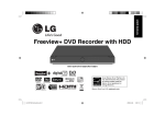
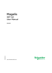
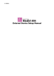
Quick guide for PRC TWD Novo-Series Reciprocator Control System Vertical stroke pattern control for 2 reciprocators also available with Trigger Functions (option) T1 THE PRC TWD Novo CONTROLLER T2 Copyright © 2000-2015 Betraco Automation CONTENTS Vertical Motion Control for 2 Spray Gun Reciprocators Preface Quick introduction Chapter 1 The Start-up Display Page, how to select a program number Chapter 2 To decide the turning (or reciprocating) points of the vertical stroke Chapter 3 Programming Chapter 4 Two Auto Modes: Individual or Synchronized Motions Chapter 5 Chapter 6 Chapter 7 Summary ... 3-4 The Start-up display page. To choose a program number ...........................................................5 Change over to MANUAL JOG Mode ........................................................................................ ...5 Starting with T1 and T2 in their home positions, position indicators show zero ...........................6 Jogging T1 and T2 up and reading their positions .......................................................................6 Teach in-programming of the turning (reciprocating) points .........................................................6 Press PROGRAM button to program the desired speeds ............................................................6 Check / Modify the values for the turning points ..........................................................................7 Enter a speed value .....................................................................................................................7 Blinking warning text on the Start-up display page ......................................................................7 Individual Mode: T1 and T2 have individual speeds and turning points .................................... ...8 Synchronized Mode: T2 runs with the same speed and turning points as T1 .............................. 8 Motion Pause at the Upper Turning Point How to program a pause time at the upper turning points ...........................................................8 Functions that facilitate the programming Copy a program and paste it into one or several other program numbers ................................... 9 Functions that facilitate the programming Copy a program and paste it into one or several other program numbers ................................... 9 Appendix - Technical Section Cabinet inside and outside and the PLC System Composition...........1 page Electric connexion of the PLC Modules ...........................................................1 page Electric hookup diagram Electric connection diagram for external equipment ...........................................................1 page PREFACE - SUMMARY OF THE IMPORTANT FUNCTIONS The brand new model PRC TWD Novo (preliminary name) offers the following design features: 1) HMI Terminal with a 5,7” TFT Color Touch Screen. 2) Full backup of the PLC Control Program on a plug-in type EEPROM Memory Capsule 3) HMI Terminal Program on a standard USB Memory for easy backup and upgrades. 4) Easily upgraded with Trigger function with necessary hardware already fitted. 5) Compact dimensions, 500x300x200mm or optionally 600x400x200. The controller PRC TWD provides the user with easy handling and excellent control functions. We recommend that the contents of this manual is studied before taking the equipment in use. IMPORTANT: The basic model of the PRC TWD Novo Control System provides programmable control of the Upper and Lower Turning Points, as well as the Motion Speed, of the Vertikal Stroke Pattern of two Reciprocators, referred to in the following text as T1 and T2. Before you start: PROGRAMMABLE UPPER STROKE LIMITS: If this is the first time you use the system, or: If you have upgraded the PLC software, or: If you, for any reason, have replaced the basic PLC unit then: You need to check the Programmable Upper Stroke Limits for T1 and T2.. The procedure to do this is described on pages 9 and 6 in this Manual. PROGRAMMING IS AS EASY AS THIS: In order to run the machines in Auto Mode, all you have to program is: 1. Lower turning point of each of the two Reciprocators, hereafter called T1 and T2 2. Upper turning point of each of T1 and T2. 3. The desired Speed of T1 and T2. 4. Optional: Program a pause time in the High Position as desired. TO RUN THE MACHINES IN AUTO MODE: 1. Select a program number, which is pre-programmed with the desired settings. 2. Press ACTIVATE 3. Start T1 & T2 That´s all. 3 SAFETY FIRST! IMPORTANT SAFETY NOTICE The reciprocators’ movement areas can be can be considered to constitute a potential Danger Zone. Therefore, never start the operation of the Reciprocators, unless you are completely certain that no person is in, or at risk of moving into that Zone. Also observe, that when you initiate Manual Jog Mode, described on page 6, the Reciprocators will automatically perform a downward motion. Also, please consider the safety regulations existing in your country concerning the installation and operation of this type of equipment. WE RECOMMEND: CHECK THIS OUT FIRST TO RUN THE MACHINES IN AUTO MODE Before the machines can perform a reciprocating (up-and-down) motion in automatic mode, the system needs to be programmed. A program must contain the information of ● The Upper and Lower Turning Points of the two Reciprocators, referred to as T1 and T2. Two easy programming methods will be shown in this manual. ● The Speed of the Reciprocating Motions. The speed is programmed in % (percent) of the maxi mum speed. ADDITIONAL FUNCTIONS, INCORPORATED IN THE CONTROLLER ● Pause in the upper turning point. The motion holds during the assigned time, before turning into a downward motion. This is repeated in every stroke cycle. ● The Operator can chose between Synchronized and Individual Motion Modes with one button push (toggle function). In Synch mode, T2 automatically assumes the same settings as T1 for speed and turning points. Also note: in Synch mode the Pause function is made ineffective. PROGRAMMING OCH EDITING The display screen area of the HMI terminal contains touch sensitive areas, or spots, serving as virtual push buttons. In order to input, or modify, a numerical value, simply press lightly on the spot, where the value is found. Then, the whole display area is transformed into a numerical key board. START AND STOP, THE FUNCTIONS ON THE START-UP DISPLAY PAGE Only the start-up display page has functions for individual start and stop of the machines. IMMEDIATE STOP - THE LARGE, ROUND BLACK BUTTON ON THE LOWER LEFT OF THE CABINET FRONT. When this button is pushed, all motions of T1 and T2 come to an immediate stop. In order to re-start the machines, this button needs to be turned a few millimeters counter-clockwise. COPY AND PASTE The start-up display page also contains a COPY and PASTE-function, offering a method to simplify and speed up the programming procedure. The function will be described later in this manual. MANUAL JOG MODE Both reciprocators can be jogged up and down manually. First, they have to be stopped in auto mode. The display page with control buttons for manual jogging can be reached from the start-up display page. Manual jogging is practical to use when we want to determine values for the High and the Low Turning Points. When we are in Manual Jog Mode, we can enter the values for the turning points by using the Teach-in method, which is even easier than programming the values via the virtual keyboard. How to perform the manual jogging is explained, step-by-step, in detail inside this manual. HOW TO CHANGE PROGRAMS AND HOW TO ACTIVATE A PROGRAM The settings we enter in a program are stored directly in the program. To activate the selected program, so that the controller can use the program to run the machines, we have to press a button labelled ACTIVATE. The ACTIVATE button can be found on almost everyone of the controller’s display pages. OPTIONAL SPRAY GUN TRIGGER FUNCTION In the version without the Trigger Function, 6 Relay Outputs are free (not used), and can be used for triggering up to 6 Spray Guns. In addition, 5 Transistor Outputs are free. Some of those can also be used as Trigger Outputs in case a relay is added. In order to incorporate the Trigger Function, the Program Software must be upgraded by replacing the Plug-in EEPROM Memory Cassette. A Pulse Generator must be fitted to the Convyor Drive Station, and a Measuring Station must be arranged. The latter can consist of a simple Photocell or, preferably, a Light Beam Array in front of the Spray Booth. 1. HANDLING IS EASY - HERE IS THE START-UP DISPLAY PAGE The image below shows the start-up display of the control system. Here we show how to select a program number (steps 1-3). 0 0 Start here 1. Press here to select a program number. The display image is now transformed into a 10-key keyboard, as shown below: This area shows the value you are entering. Always check that the value is OK. 2. Choose program 1 by pressing the digit 1 key. 3. Then press Enter. Now, the display again shows the start-up display, with program nbr 1 selected, as shown below: Next, let us find out find out what values for the turning points we should enter into the program. First, press the button marked ”MANUAL UP/DOWN” 0 Next we will manually operate the reciprocators up and down. 5 2. MANUAL JOG & TEACH-IN PROGRAMMING METHOD By manually jogging the guns up or down, we will establish the digital values for the upper and lower turning points, which we will enter into our program. By using the ”TEACH IN-function” this procedure is very fast and easy! WARNING: Manual Mode starts the reciprocators automatically, running them down to their bottom (Home) positions. Position displays will indicate 0 for both T1 and T2. . Press here to select MANUAL JOG MODE. Note the WARNING above! Now the button changes both text contents and color shade, which is shown in the lower picture. . Press and hold the button T1 UP until the spray guns are in the desired position for the LOW TURNING POINT. . Press the Teach In Button labeled T1 LOW TURN in the lower picture. This saves the T1 Low Turning Point into the program you selected before (program nbr 1). . Now, run the spray guns up to the desired HIGH TURNING POINT. . Press T1 HIGH TURN in the picture to save this position in the program. Repeat the above procedure for T2. When you are done with Manual Jogging, press the MANUAL-button again, so that its appearance again shows: Now, press the PROGRAM button to go to the Program display page, to check the settings for the turning points. There you will set the desired speed, as well. 6 3. CHECK/ADJUST TURNING POINTS & PROGRAM THE SPEEDS On this display page you can check and, if needed, adjust the turning points, and you also have to program the speed for T1 here. This page displays all the parameters required to run T1 in Auto Mode: -Program number -Upper turning point -Lower turning point -Speed (-Pause timer setting) 186 IMPORTANT: The settings in a program must be ACTIVATED before they can be used. Press ACTIVATE when you have finished programming. IMPORTANT: Set the desired speed (in percent of maximum speed). Press here to go to T2 programming page (when you are finished with T1). Press the surface indicated by the arrow if you want to adjust this value. Press here if you want to pogram, or change, the value for the High Turning Point. When you are satisfied with the settings for the turning points: Press T2 PROG button to go to the T2 Programming display page. When you have finished programming the settings for T1 and T2: Press ACTIVATE button. Now, press START PAGE to go back to the Start-up Display page (below): These buttons are used for starting and stopping T1 and T2 individually in AUTO Mode. OBSERVE: f this (blinking) Alarm Message appears, you have simply forgtten to leave the Manual Mode. Just return to the Manual Display Page and give the MANUAL JOGGING Button another push. 7 4. RUNNING T1 AND T2 SYNCHRONIZED A Push Button, with which you can switch (toggle) between Individual and Synchronized Operation Mode. The Reciprocators T1 and T2 can be operated in two different Auto Modes: A Label, indicating which mode is selected (Individual or Synchronized). INDIVIDUAL OR SYNCHRONIZED. In Individual Mode, T1 and T2 are started and stopped individually and run with individual settings with regard to speed and turning points. In Synchronized Mode, the start of T1 also starts T2. T2 automatically assumes the same speed and turning points as T1, regardless of how T2 was programmed. The one of T1 and T2, that reaches the upper turning point first, will automatically wait for the other one, so as to start the downward travel simultaneously. NOTE: When you leave the Synchronized Mode to run the machines Individually again, the programmed settings for T2 will be re-entered automatically to control T2 in Individual Mode. 5. PAUSE TIMERS AT T1 AND T2 UPPER TURNING POINTS A Pause time can be programmed for T1 and/or T2 in any program number. The Reciprocator will stop and hold its motion the programmed time at the Upper Turning Point, before it starts its downward movement. The Pause time is programmed in units of 1/10 second. Thus if you enter the value 20, the Reciprocator will hold its motion for 2 seconds. If you program the value 5, it will hold for 0.5 second. The value is entered here and is directly stored in the selected program number. Note: In order to use the Pause Timer setting, push the ACTIVATE button. 7 6. PROGRAMMING AID The System is provided with functions that can be used to speed up the programming job if you want to develop several similar programs. By means of COPY and PASTE you can quickly produce several identical programs and then make adjustments as required. 2) 1) 3) Here´s how: 1) Copy: Choose a program, that contains the settings you want to copy, for example: program 1. Press the button COPY. 2) Change program number: Press PROG NR and choose, for example program 2, and press ENTER. 3) Paste: Press the button PASTE. 4) Paste the copied program into more program positions: Choose another program number, for example program 3. Press once more on PASTE. Now, you have made programs 1, 2 and 3 identical. If required, you can now choose any of these programs and make desired adjustments. This method is practical if you have several programs, which have similar settings. Normal proceedings when you have a number of complete programs and want to run the machines in Auto mode: 1. Choose a suitable program 2. Press ACTIVATE 3. Start the machines T1 and T2. 8 7. SETTING T1 & T2 STROKE UPPER LIMITS 1. On the Start-up Display Page, press TO SETUP. The following Screen appears: The dashes indicate that access is prevented. 2. Press here. A Numeric Key board appears on the Screen 3. Enter the Numeric Password Code (which you get from your Dealer. Then, press ENTER 4. Now, you have access to the Setup Page. Press here. The Setup Page appears. 5. If Upper Limits boxes already contain values (should be around 200), you may not have to modify. In other case, set the values to approx. the same as indicated in the picture to the left. Then, go to the MANUAL JOG Screen via the Start Page, refer to pages 5-6 in this manual, and move the spray guns up to the point, where you want to set the upper limit. Then go back to this Screen to modify the values accordingly. 9 Technical section PGC Reciprocator Control and Trigger System PGC TWD RC-series Connection diagram for reciprocators with incremental pulse encoders (A- & B-channels) for the vertical movement. CABINET AND PLC SYSTEM COMPOSITION Cabinet outside view Explanation of numbering HMI-Terminal HMI STU855 with a 5.7” Touch Sensitive TFT Color Screen Stop button. Causes immediate stop of T1 and T2 motions when pressed. To reset: Turn slightly Counter Clockwise. 230VAC Main Power Breaker. Can also be mounted on the Cabinet Side. T1 and / or T2 Running Indicator Lamp. Cabinet inside view & PLC Composition HMI-Terminal Model HMI STU 855 Explanation of numbering Communication Module Model TWDNOZ485D Comm. Cable between PLC and HMI Base PLC Model TWD LMDA20DRT. Left row: 12 digital inputs Right row: 2 trans.outputs + 6 relay outputs Module TM2AVO2HT with 2 analog outputs, 0...10V for T1 and T2 Speed Control Module TM2DDO8TT with 8 trans.outputs. 4 are used to control T1 and T2 up/down Plug in Memory Chip TWDXCPMFK64 contains the Control Program Power Supply ABL8REM24030 Primary 230VAC, Out 24VDC 3A Auto Fuse PLC MODULES - ELECTRIC CONNEXION TWD LMDA 20DRT ELECTRIC DIAGRAM PLC SYSTEM T1&T2 Run Lamp Inputs Screw Terminal Block Outputs Screw Terminal Block 7 Outputs Not Used (Spare) PROTECTIVE EARTH 0V +24V 12 Inputs: address %I0.0 - %I0.11 8 Outputs: %Q0.0 - %Q0.1 = 2 Transistor %Q0.2 - %Q0.7 = 6 Relay TM2 AVO2HT 2 Analog Outputs T1 Speed 0...+10V Addr.: %QW1.0 T2 Speed 0...+10V Addr.: %QW1.1 8 Transistor Outputs address %Q2.0 - %Q2.7 7 Outputs Not Used (Spare) %Q2.2 = T1 up %Q2.3 = T1down %Q2.4 = T2 up %Q2.5 = T2 down The rest are free. NEXT PAGE: CONNEXION OF INCOMING CABLES FROM T1 & T2 CONNECTIONS AT THE MAIN TERMINAL INSIDE THE ENCLOSURE Hookup with two Reciprocators (plinth row version) %Q2.5 25 4 T2 down %Q2.4 24 3 T2 up %Q2.3 23 4 T1 down %Q2.2 22 3 T1 up %Q0.0 21 EXPLANATION Remote = connexn. remote control LS = Limit Switch T1 = Reciprocator # 1 T2 = Reciprocator # 2 %Q2.x = Discrete PLC output %I0.x = Discrete PLC intput %QW1.x = Analog output x refers to channel nbr. %QW1.1 20 7 T2 speed 0...10V %QW1.0 19 7 T1 spedd 0...10V 0VDC Black 18 2 SUPPLY ANA. MODULE 0VDC Black 17 2 T1 & T2 Freq.converter. COM SUPPLY PLC 0VDC Black 16 2 T1 & T2 Pulse gen. 0V supply 0VDC Brown 15 2 +24V Red 14 1 FR. PWR SUPPLY MATN. PLC-ING. FR. PWR SUPPLY SUPPLY ANA. MODULE +24V Red 13 1 SUPPLY PLC +24V Red 12 1 +24V Red 11 1 0VDC +24V T1 & T2 Pulse gen. +24V supply All Stop Black Stop Button in Front %I0.9 10 %I0.8 9 %I0.11 8 6 T2 LS-top %I0.10 7 6 T1 LS-top %I0.7 6 8 T2 B-channel %I0.6 5 9 T2 A-channel %I0.5 4 5 T2 LS-home %I0.2 3 5 T1 LS-home %I0.1 2 8 T1 B-channel %I0.0 1 9 T1 A-channel PLC Addresses Remote Running Lamp Remote Start LS2-2 LS1-2 LS2-1 LS1-1 Cable wire numbers Betraco Automation, Fritsla, Sweden • Tel.: +46-320-709 70 • cell phone: +46-705-23 24 99 • e-mail: [email protected] • internet: http://www.betraco.se