1
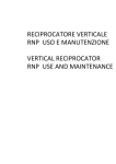
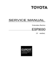
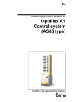
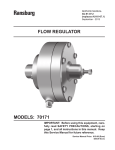
Instructions
Hydraulic Fluid
Controls
308395D
EN
Regulates hydraulic pressure and flow when used with Graco’s Dyna-Star™ and
Power-Star™ hydraulic-powered lubricant pumps. For professional use only.
Model 236864
Used with Dyna-Star™
1500 psi (10.5 MPa, 105 bar) Maximum Working Pressure
3 gpm (11 liters/min) Maximum Flow Rate
Important Safety Instructions
Read all warnings and instructions in this
manual. Save these instructions.
Model 236865
Used with Power-Star™
1500 psi (10.5 MPa, 150 bar) Maximum Working Pressure
12 gpm (45 liters/min) Maximum Flow Rate
Hydraulic fluid controls are designed to control
hydraulic fluids only in a hydraulic power system. Any
other fluids can cause unsafe operating conditions
and results in component rupture, fire, or explosion
which could result in serious injury, including fluid
injection.
Model 236864
Model 236865
Warnings
Warnings
The following warnings are for the setup, use, grounding, maintenance, and repair of this equipment. The exclamation point symbol alerts you to a general warning and the hazard symbols refer to procedure-specific risks. When
these symbols appear in the body of this manual or on warning labels, refer back to these Warnings. Product-specific
hazard symbols and warnings not covered in this section may appear throughout the body of this manual where
applicable.
WARNING
FIRE AND EXPLOSION HAZARD
When flammable fluids are present in the work area, such as gasoline and windshield wiper fluid, be
aware that flammable fumes can ignite or explode. To help prevent fire and explosion:
• Use equipment only in well ventilated area.
• Eliminate all ignition sources, such as cigarettes and portable electric lamps.
• Keep work area free of debris, including rags and spilled or open containers of solvent and gasoline.
• Do not plug or unplug power cords or turn lights on or off when flammable fumes are present.
• Ground all equipment in the work area.
• Use only grounded hoses.
• Stop operation immediately if static sparking occurs or you feel a shock. Do not use equipment
until you identify and correct the problem.
• Keep a working fire extinguisher in the work area.
SKIN INJECTION HAZARD
High-pressure fluid from dispensing device, hose leaks, or ruptured components will pierce skin. This
may look like just a cut, but it is a serious injury that can result in amputation. Get immediate surgical
treatment.
• Do not point dispensing device at anyone or at any part of the body.
• Do not put your hand over the fluid outlet.
• Do not stop or deflect leaks with your hand, body, glove, or rag.
• Follow the Pressure Relief Procedure when you stop dispensing and before cleaning, checking, or
servicing equipment.
• Tighten all fluid connections before operating the equipment.
• Check hoses and couplings daily. Replace worn or damaged parts immediately.
2
308395D
Warnings
WARNING
EQUIPMENT MISUSE HAZARD
Misuse can cause death or serious injury.
• Do not operate the unit when fatigued or under the influence of drugs or alcohol.
• Do not exceed the maximum working pressure or temperature rating of the lowest rated system component. See Technical Data in all equipment manuals.
• Use fluids and solvents that are compatible with equipment wetted parts. See Technical Data in all
equipment manuals. Read fluid and solvent manufacturer’s warnings. For complete information about
your material, request MSDS from distributor or retailer.
• Do not leave the work area while equipment is energized or under pressure.
• Turn off all equipment and follow the Pressure Relief Procedure when equipment is not in use.
• Check equipment daily. Repair or replace worn or damaged parts immediately with genuine manufacturer’s replacement parts only.
• Do not alter or modify equipment. Alterations or modifications may void agency approvals and create
safety hazards.
• Make sure all equipment is rated and approved for the environment in which you are using it.
• Use equipment only for its intended purpose. Call your distributor for information.
• Route hoses and cables away from traffic areas, sharp edges, moving parts, and hot surfaces.
• Do not kink or over bend hoses or use hoses to pull equipment.
• Keep children and animals away from work area.
• Comply with all applicable safety regulations.
TOXIC FLUID OR FUMES HAZARD
Toxic fluids or fumes can cause serious injury or death if splashed in the eyes or on skin, inhaled, or swallowed.
• Read MSDSs to know the specific hazards of the fluids you are using.
• Store hazardous fluid in approved containers, and dispose of it according to applicable guidelines.
• Always wear chemically impermeable gloves when spraying, dispensing, or cleaning equipment.
308395D
3
Installation
Installation
Grounding
The equipment must be grounded to reduce the risk
of static sparking and electric shock. Electric or static
sparking can cause fumes to ignite or explode.
Improper grounding can cause electric shock.
Grounding provides an escape wire for the electric
current.
Z V W
Pump: use ground wire and clamp (supplied). Loosen
grounding lug locknut (W) and washer (V). Insert one
end of a 12 ga (1.5 mm2) minimum ground wire (Y) into
the slot in lug (Z) and tighten the locknut securely. Connect the other end of the wire to a true earth ground.
Order Part No. 237569 Ground Wire and Clamp.
Hydraulic Hoses and Fluid Outlet Hoses: use only
electrically conductive hoses.
Y
FIG. 1
Hydraulic Power Supply and Air Compressor: follow
manufacturer’s recommendations.
Any pails used when flushing: use only metal
grounded pails when flushing. Make firm metal-to-metal
contact between a metal part of the dispense valve and
the pail. Use the lowest possible pressure.
4
308395D
Installation
Typical Installation
C
E
L
C
L
E
A
G
J
G
K
H
J
D
K
F
F
B
H
D
Model 236864
Model 236865
FIG. 2: Typical Installation
Key:
A
B
C
D
E
F
G
H
J
K
L
Hydraulic Control, 236864
Hydraulic Control, 236865
Hydraulic Return Line
Hydraulic Outlet, 3/4 npsm (A), 1 1/4 npsm(B)
Return Line Shutoff Valve
Hydraulic Inlet, 3/8 npsm (A), 3/4 npsm (B)
Supply Line Shutoff Valve
Pressure Gauge
Pressure Reducing Valve
Flow Control Valve
Hydraulic Supply Line (use only Graco hydraulic power
supply)
Hydraulic Fluid Control: The hydraulic fluid control provides pressure regulation, flow regulation, and pump
isolation. See the Typical Installation as a guide. For
assistance in designing a system to suit your needs,
contact your Graco Representative.
308395D
Pressure Regulation: The hydraulic fluid control pressure reducing valve (J) reduces the hydraulic oil pressure to the operating pressure required for application.
Flow Regulation: The hydraulic fluid control valve (K)
limits the maximum amount of oil flow to the motor to
keep the hydraulic motor within the recommended cycle
rate limit. This prevents pump runaway. The limit on the
Dyna-Star™ is 60 cpm. The limit on the Power-Star™ is
66 cpm.
Pump Isolation: The hydraulic fluid control (A and B) has
ball valves on the supply and return sides of the manifold. The ball valves isolate the hydraulic fluid control
and pump for servicing without stopping the hydraulic
power source.
5
Installation
Installation Notes
Hydraulic Components
NOTICE
The hydraulic supply system must be kept clean at all
times to reduce the risk of damaging the reciprocator
hydraulic power supply.
•
• Always turn off the supply side valve (G) to avoid
possible serious injury or component damage.
See the Typical Installation on page 5.
Blow out all hydraulic lines with air, flush thoroughly
with solvent, and then blow out the air again before
connecting the lines to the reciprocator.
Maximum Working Pressure of Accessories
• To reduce the risk of serious injury including fluid
injection and splashing in the eyes or on the skin,
which may be caused if a component ruptures, all
accessories added to the reciprocator power
supply side must have at least 1500 psi (10.5
MPa, 105 bar) maximum working pressure and
those to the pump fluid outlet side must have at
least a 375 psi (2.6 MPa, 26 bar) maximum
working pressure for Dyna-Star™ and 1500 psi
(10.5 MPa, 105 bar) for the Power-Star™.
Hydraulic Power Supply
To reduce the risk of over pressurizing the hydraulic
reciprocator, which could cause a rupture and
serious injury, including fluid injection, the hydraulic
power must have a means to limit the incoming fluid
flow to the reciprocator to a maximum of 3 gpm (11
liter/min) at 1500 psi (10.5 MPa, 105 bar) for the
Dyna-Star™ and 10 gpm (37 liter/min) at 1500 psi
(10.5 MPa, 105 bar) for the Power-Star™.
•
Do not kink hoses. Adjust swivel connections if necessary.
•
Always use permanently coupled electrically conductive hoses.
•
Refer to the application data from Graco to make
determinations as to the location and height to
mount the control.
Recommended Hydraulic Oil
Use Graco approved Hydraulic Oil or a premium ISO
grade 46 petroleum-based hydraulic oil containing rust
and oxidation inhibitors and anti-wear agents.
6
•
Before using any other type of oil in this control,
contact your Graco distributor. Unauthorized use of
lesser grade oil or substitutes may void the warranty.
•
See Technical Data on page 12 for hydraulic oil
working temperatures.
308395D
Operation
Operation
Pressure Relief Procedure
Hydraulic Fluid Level Check
Follow the Pressure Relief Procedure whenever
you see this symbol.
This equipment stays pressurized until pressure is
manually relieved. To help prevent serious injury from
pressurized fluid, such as skin injection, splashing
fluid and moving parts, follow the Pressure Relief
Procedure when you stop spraying and before
cleaning, checking, or servicing the equipment.
Check the hydraulic fluid level in the hydraulic power
supply before each use, and add fluid as necessary to
fill the lines.
Starting the Pump
•
Never exceed 1500 psi (10.5 MPa, 105 bar) Maximum Hydraulic Pressure to the control.
•
Never exceed 375 psi (2.6 MPa, 26 bar) Maximum
Outlet Pressure from the control when used with a
1/4:1 Dyna-Star™ pump.
•
Never exceed 1500 psi (10.5 MPa, 105 bar) Maximum Outlet Pressure from the control when used
with a 1:1 Power-Star™ pump.
•
Be sure all accessories added to the reciprocator
power supply side of the control are capable of at
least 1500 psi (10.5 MPa, 105 bar) maximum working pressure and all of those for the pump fluid outlet side of the control have at least 375 psi (2.6 MPa,
26 bar) maximum working pressure for Dyna-Star™
and 1500 psi (10.5 MPa, 105 bar) for Power-Star™.
1. Close the supply line shutoff valve (G), and then
return line shutoff valve (E).
2. Hold open the dispensing valve to relieve pressure.
3. Place a container under the drain valve to catch any
drainage. Open the pump outlet drain valve.
4. Leave the drain valve open until you are ready to
pump again.
If you suspect that the dispensing valve nozzle or hose
is completely clogged, or that pressure has not been
fully relieved after following the steps above, VERY
SLOWLY loosen the hose end coupling and relieve pressure gradually then loosen completely, now clear the
obstruction.
Emergency Stop Procedure
1. Turn on hydraulic power supply.
Close the red-marked supply line shutoff valve marked
STOP.
2. Open the return line shutoff valve (E) first and slowly
open the hydraulic supply shutoff valve (G).
Before Starting the Pump
3. Remove the cap on the pressure reducing valve to
reveal the cap screw adjustment.
When starting up the hydraulic system, open the return
line shutoff valve (E) first.
4. Adjust the hydraulic inlet pressure from 50 to 1500
psi (0.3 to 10.5 MPa, 3 to 105 bar) with an allen
wrench inserted in the regulator pressure control
adjustment on the pressure reducing valve (J).
Increasing the inlet pressure (clockwise) increases
the pump outlet pressure. Decreasing the inlet pressure (counter clockwise) decreases the pump outlet
pressure.
5. Always use the lowest pressure possible to obtain
the desired results. This reduces pump wear.
308395D
7
Repair
Shutdown
Always shut off the supply line shutoff valve (E) first, and
then the return line shutoff valve (G). This is to prevent
over pressurizing the reciprocator or its seals. When
starting the hydraulic system, open the return line shutoff valve (G) first. See page 5.
Repair
Flow Control Repair
1. Relieve pressure, see page 7.
There are two basic repairs to the hydraulic fluid control;
pressure control repair and flow control repair.
Pressure Control Repair
1. Relieve pressure, see page 7.
2. Remove the flow control valve (K).
3. Clean the flow control valve (K) with compatible solvent.
4. Install the flow control valve in the control.
2. Remove the pressure reducing valve (J).
5. Try the system with the clean valve. Follow the
Starting the Pump procedure on page 7.
3. Clean the pressure reducing valve (J) with a compatible solvent.
6. If the control still does not control the flow properly,
replace the valve.
4. Install the pressure reducing valve in the control.
5. Try the system with the clean valve. Follow the
Starting the Pump procedure on page 7.
6. If the control still does not regulate the pressure
properly, replace the valve.
8
308395D
Troubleshooting
Troubleshooting
Problem
Cause
Solution
No pressure on gauge, or low pressure on gauge
Hydraulic power supply malfunction
or mis-adjustment
Adjust the hydraulic power supply. If
the problem remains, refer to the
hydraulic power supply instruction
manual.
Pressure reducing valve is backed
out
Adjust the pressure reducing valve.
Can’t adjust pressure with the pressure reducing valve
Clogged valve
Clean the pressure reducing valve.
Insufficient hydraulic power supply
pressure
Adjust the hydraulic power supply
pressure. If problem remains refer
to the hydraulic power supply
instruction manual.
Gauge will not re-zero with the
hydraulic supply and return line
shutoff valves closed
Leak in the supply line shutoff valve
(G)
Open the return line shutoff valve
(E) to remove pressure.
Damaged gauge
Replace gauge.
Pump runs away
Contaminated flow control valve
Remove and clean the flow control
valve.
308395D
9
Parts
Parts
111
112
1
110
102
103
109
105
108
113
Includes items
113a & 113b
104
113b
113a
110
106
107
103
Model 236864 Hydraulic Fluid Control
Ref.
102
103
104
105
106
107
108
109
110
10
Part
108537
112714
112567
112578
112581
112705
112707
112708
112715
Description
VALVE, ball
HOSE, coupled, 3 ft
GAUGE, pressure, fluid
VALVE, ball
SWIVEL, union, 90°
SWIVEL, union, 90°
ADAPTER, male
ADAPTER, male
HOUSE, couple, 3 ft
Qty.
1
2
1
1
1
1
1
1
2
Ref.
111
112
113
Part
155494
160327
189837
Description
UNION, swivel, 90°
UNION, swivel, 90°
MANIFOLD, 3 gpm, includes
replaceable items 113a and 113b
113a 119902 VALVE, pressure reducing
113b 112712 VALVE, flow regulating, 3 gpm
Qty.
1
1
1
1
1
308395D
Parts
111
105
112
104
110
109
102
108
113
113b
Includes items
113a & 113b
103
113a
107
106
110
111
Model 236865 Hydraulic Fluid Control
Ref.
102
103
104
105
106
107
108
109
110
Part
108537
112567
112579
112580
112705
112706
112708
112709
112715
308395D
Description
VALVE, ball
GAUGE, pressure, fluid
VALVE, ball
SWIVEL, union, 90°
SWIVEL, union, 90°
SWIVEL, union, 90°
ADAPTER, male
ADAPTER, male
HOSE, coupled, 3 ft
Qty.
1
1
1
1
1
1
1
1
2
Ref.
111
112
113
Part
112716
160327
189838
Description
HOSE, coupled, 3 ft
UNION, swivel, 90°
MANIFOLD, 12 gpm, includes
items 113a and 113b
113a 119903 VALVE, pressure reducing
113b 112713 VALVE, flow regulating, 12 gpm
Qty.
2
1
1
1
11
Technical Data
Technical Data
Hydraulic Fluid Controls: Dyna-Star™
US
Maximum fluid working pressure
Pressure adjusting range
Flow setting
Maximum fluid temperature
Weight
Wetted materials
Sound Pressure
Metric
10.5 MPa, 105 bar
3.5-10.5 MPa, 35-105 bar
11 lpm
55°C
1500 psi
500-1500 psi
3 gpm
130°F
11 lb
5 kg
Aluminum, steel, nitrile
< 70 dB(A)
Dimensions
See Below
Hydraulic Fluid Controls: Power-Star™
Maximum fluid working pressure
Pressure adjusting range
Flow setting
Maximum fluid temperature
Weight
Wetted materials
Sound Pressure
1500 psi
300-1500 psi
12 gpm
130°F
22 lb
10.5 MPa, 105 bar
2.0-10.5 MPa, 20-105 bar
45 lpm
55°C
10 kg
Aluminum, steel, nitrile
< 70 dB(A)
Dimensions
See Below
Dimensions
3 x 0.406 in.
Use 3/8 in.
(9 mm) screws
3 x 0.406 in.
Use 3/8 in.
(9 mm) screws
1.875 in.
(47.63 mm)
3.75 in.
(95.25 mm)
12
2.125 in.
(53.97 mm)
4.25 in.
(107.95 mm)
4.25 in.
(107.95 mm)
5.25 in.
(133.35 mm)
Model 236864
Model 236865
308395D
Notes
Notes
308395D
13
Graco Standard Warranty
Graco warrants all equipment referenced in this document which is manufactured by Graco and bearing its name to be free from defects in
material and workmanship on the date of sale to the original purchaser for use. With the exception of any special, extended, or limited warranty
published by Graco, Graco will, for a period of twelve months from the date of sale, repair or replace any part of the equipment determined by
Graco to be defective. This warranty applies only when the equipment is installed, operated and maintained in accordance with Graco’s written
recommendations.
This warranty does not cover, and Graco shall not be liable for general wear and tear, or any malfunction, damage or wear caused by faulty
installation, misapplication, abrasion, corrosion, inadequate or improper maintenance, negligence, accident, tampering, or substitution of
non-Graco component parts. Nor shall Graco be liable for malfunction, damage or wear caused by the incompatibility of Graco equipment with
structures, accessories, equipment or materials not supplied by Graco, or the improper design, manufacture, installation, operation or
maintenance of structures, accessories, equipment or materials not supplied by Graco.
This warranty is conditioned upon the prepaid return of the equipment claimed to be defective to an authorized Graco distributor for verification of
the claimed defect. If the claimed defect is verified, Graco will repair or replace free of charge any defective parts. The equipment will be returned
to the original purchaser transportation prepaid. If inspection of the equipment does not disclose any defect in material or workmanship, repairs will
be made at a reasonable charge, which charges may include the costs of parts, labor, and transportation.
THIS WARRANTY IS EXCLUSIVE, AND IS IN LIEU OF ANY OTHER WARRANTIES, EXPRESS OR IMPLIED, INCLUDING BUT NOT LIMITED
TO WARRANTY OF MERCHANTABILITY OR WARRANTY OF FITNESS FOR A PARTICULAR PURPOSE.
Graco’s sole obligation and buyer’s sole remedy for any breach of warranty shall be as set forth above. The buyer agrees that no other remedy
(including, but not limited to, incidental or consequential damages for lost profits, lost sales, injury to person or property, or any other incidental or
consequential loss) shall be available. Any action for breach of warranty must be brought within two (2) years of the date of sale.
GRACO MAKES NO WARRANTY, AND DISCLAIMS ALL IMPLIED WARRANTIES OF MERCHANTABILITY AND FITNESS FOR A
PARTICULAR PURPOSE, IN CONNECTION WITH ACCESSORIES, EQUIPMENT, MATERIALS OR COMPONENTS SOLD BUT NOT
MANUFACTURED BY GRACO. These items sold, but not manufactured by Graco (such as electric motors, switches, hose, etc.), are subject to
the warranty, if any, of their manufacturer. Graco will provide purchaser with reasonable assistance in making any claim for breach of these
warranties.
In no event will Graco be liable for indirect, incidental, special or consequential damages resulting from Graco supplying equipment hereunder, or
the furnishing, performance, or use of any products or other goods sold hereto, whether due to a breach of contract, breach of warranty, the
negligence of Graco, or otherwise.
FOR GRACO CANADA CUSTOMERS
The Parties acknowledge that they have required that the present document, as well as all documents, notices and legal proceedings entered into,
given or instituted pursuant hereto or relating directly or indirectly hereto, be drawn up in English. Les parties reconnaissent avoir convenu que la
rédaction du présente document sera en Anglais, ainsi que tous documents, avis et procédures judiciaires exécutés, donnés ou intentés, à la suite
de ou en rapport, directement ou indirectement, avec les procédures concernées.
Graco Information
For the latest information about Graco products, visit www.graco.com.
TO PLACE AN ORDER, contact your Graco distributor or call to identify the nearest distributor.
Phone: 612-623-6928 or Toll Free: 1-800-533-9655, Fax: 612-378-3590.
All written and visual data contained in this document reflects the latest product information available at the time of publication.
Graco reserves the right to make changes at any time without notice.
For patent information, see www.graco.com/patents.
Original instructions. This manual contains English. MM 308395
Graco Headquarters: Minneapolis
International Offices: Belgium, China, Japan, Korea
GRACO INC. AND SUBSIDIARIES • P.O. BOX 1441 • MINNEAPOLIS MN 55440-1441 • USA
Copyright 1994, Graco Inc. All Graco manufacturing locations are registered to ISO 9001.
www.graco.com
Revised November 2012