1
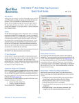
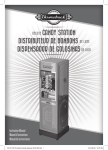
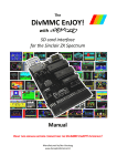
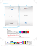
Copyright Next Wave Automation All Rights Reserved. Version 2.1.0 11 April 2015 Updates of this manual may be available at www.nextwaveautomation.com. CNC Shark, CNC Shark Pro, CNC Shark Pro Plus, CNC Shark Pro Plus HD, CNC Shark HD 2.0, CNC Shark HD 3.0 and the configuration of these products are either registered trademarks or trademarks of Next Wave Automation. Software copyright by Next Wave Automation. All rights reserved.All other trademarks are the property of their respective owners. To Our Customers Thank you for purchasing the CNC Shark 4th Axis Table Top Accessory! Your CNC Shark 4th Axis Table Top Accessory brings enhanced CNC machining capabilities to your CNC Shark system. This manual tells you how to install and use your CNC Shark 4th Axis Table Top Accessory. Please read the manual carefully. The manual also includes our warranty and important safety information. This manual has been written with the assumption that the owner is familiar with the basic operation of a computer as well as the basic aspects of techniques for the safe operation of woodworking power tools. Information in this manual is subject to change without notice. Again, thank you for purchasing the CNC Shark 4th Axis Table Top Accessory. If you ever have any questions or comments, feel free to contact us at the address below. Next Wave Automation, LLC 7235 Progress Street Holland, OH 43528 www.nextwaveautomation.com Email – [email protected] Support Email – [email protected] Support Phone – (419) 491-4520 V2.1.0 CNC Shark Control Panel 2.1 |1 CNC Shark Registration Information Record your CNC Shark 4th Axis Table Top Accessory, Control Panel 2.1 and other Shark accessory registration codes here for safe keeping and central record keeping. Shark Control Panel 2.1 : ____________________________________________ Shark Touch Plate: _________________________________________________ Shark Touch Probe: ________________________________________________ Shark 4th Axis Table Top Kit: _________________________________________ Control Box Serial Number: _________________________________________ VCarve Pro User Name: ____________________________________________ VCarve Pro License Code: ___________________________________________ Cut3D User Name: _________________________________________________ Cut3D License Code: ________________________________________________ Note: Depending on the Shark model and accessories you have purchased, you may not have one or more of the items listed above at this time. V2.1.0 CNC Shark Control Panel 2.1 |2 Note: You can click on a page number in the contents and quickly navigate to that section. Contents To Our Customers ................................................................................................................................... 1 CNC Shark Registration Information ........................................................................................................ 2 Warranty ................................................................................................................................................. 5 Safety ...................................................................................................................................................... 6 Emergency Stop................................................................................................................................... 6 CNC Shark Operations Safety Instructions ............................................................................................ 7 CNC Shark Hardware and Project Safety Instructions ........................................................................... 9 4th Axis Overview ................................................................................................................................... 11 In the Box .......................................................................................................................................... 11 Additional Requirements ............................................................................................................... 11 Workflow .......................................................................................................................................... 12 Create the Design and Toolpath(s) ................................................................................................. 12 Machining the Part ........................................................................................................................ 14 First Use Setup Steps ............................................................................................................................. 15 Installing the A Axis Controller Module .............................................................................................. 15 Mounting the Chuck .......................................................................................................................... 15 Install the SCP 2.x and Register .......................................................................................................... 16 Install the CNC Shark Rotary Post Processors ..................................................................................... 16 Check Gantry Height .......................................................................................................................... 17 A|4th Axis Preferences ....................................................................................................................... 17 4th Axis Physical Setup ........................................................................................................................... 18 Motor/Chuck and Tailstock Positioning .............................................................................................. 18 SCP 2.x A|4th Axis Preferences ........................................................................................................... 19 Establishing Tool Location Relative to the Rotary ............................................................................... 21 Load and Run GCode ............................................................................................................................. 23 4th Axis Setup Test and Skills Development ............................................................................................ 24 4th Axis Test Project ........................................................................................................................... 24 Skills Development ............................................................................................................................ 24 Appendices............................................................................................................................................... i V2.1.0 CNC Shark Control Panel 2.1 |3 4th Axis Layout, SCP2 Preferences and Post Processor .............................................................................. ii Carriage Facing the Table Axis Motor ................................................................................................... ii Carriage Not Facing the Table Axis Motor ........................................................................................... iii 4th Axis Setup and Use Tips ...................................................................................................................... v Determining the Chuck Radius ............................................................................................................. v Positioning Along the Centerline .......................................................................................................... v Installing the A Axis Control Module – Step by Step ............................................................................... vii Note: You can click on a page number in the contents and quickly navigate to that section. V2.1.0 CNC Shark Control Panel 2.1 |4 Warranty [Contents] [4th Axis Overview] [First Use Setup Steps] [4th Axis Physical Setup] [Load & Run GCode] [4th Axis Setup Test] [Appendices] Next Wave Automation warrants to the original retail purchaser of a CNC Shark machine and purchased from an authorized CNC Shark machine distributor that the CNC Shark and any Shark accessories purchased with the CNC Shark machine will be free from defects in material and workmanship for ONE YEAR from the date of purchase. This warranty is for parts and labor to correct the defect, and does not cover the cost of shipping the defective item(s) to Next Wave Automation for repair. This warranty does not apply to defects arising from normal wear and tear, misuse, abuse, negligence, accidents, unauthorized repair or alteration, or lack of maintenance. This warranty is void if the CNC Shark machine or any portion of the CNC Shark machine is modified without the prior written permission of Next Wave Automation, LLC, or if the CNC Shark machine is located or has been used outside the country of residence of the authorized CNC Shark machine distributor from whom the CNC Shark machine was purchased. Please contact Next Wave Automation to take advantage of this warranty. If Next Wave Automation determines the CNC Shark machine or CNC Shark accessory is defective in material or workmanship, and not due to normal wear and tear, misuse, abuse, negligence, accidents, unauthorized repair or alteration, or lack of maintenance, then Next Wave Automation will, at its expense and upon proof of purchase, send replacement parts to the original retail purchaser necessary to cure the defect. Next Wave Automation will repair the CNC Shark machine or CNC Shark accessory provided the necessary CNC Shark machine component is returned to Next Wave Automation, shipping prepaid, with proof of purchase and within the warranty period. Next Wave Automation disclaims any and all other express or implied warranties, including fitness for a particular purpose. Next Wave Automation shall not be liable for death, injuries to persons or property, or incidental, consequential, contingent or special damages arising from the use of the CNC Shark machine. [Contents] [4th Axis Overview] [First Use Setup Steps] [4th Axis Physical Setup] [Load & Run GCode] [4th Axis Setup Test] [Appendices] V2.1.0 CNC Shark Control Panel 2.1 |5 Safety [Contents] [4th Axis Overview] [First Use Setup Steps] [4th Axis Physical Setup] [Load & Run GCode] [4th Axis Setup Test] [Appendices] The CNC Shark, along with a router or other power tool, is a computer-numerically-controlled (CNC) routing system. As such, it is a powerful system that can reduce your woodworking risks by providing a method of cutting wood and other materials without having to interact with the cutting tool(s) or material during the fabrication process. As with all power tools, your care and attention are required to ensure that you use your CNC Shark safely. Next Wave Automation assumes you will use your CNC Shark safely and follow accepted safety precautions and practices for woodworking and machining. Emergency Stop [Safety] [Operations Safety] [Hardware & Project Safety] [Contents] There are 2 ways you can immediately stop your CNC Shark. CNC Shark and CNC Shark Pro users should use a power strip with an on/off switch. The first is the Emergency Stop button on the Control Panel. The E-Stop button is available regardless of whether you are using the File or the Jog panel. Figure 1 - E-Stop on Shark Control Panel The second is the E-Stop button on the Control Box of the CNC Shark Pro Plus and CNC Shark Pro Plus HD – or the on/off switch on the power strip recommended for use with the CNC Shark and CNC Shark Pro. V2.1.0 CNC Shark Control Panel 2.1 |6 Figure 2 - Emergency Stop Button on Enhanced Control Box Hitting either will immediately stop the CNC Shark movement. This will also stop the router if it is plugged into the Control Box. For CNC Shark and Shark Pro users who have plugged the Shark Power Supply and router into a power strip, the power strip’s on/off switch serves the same purpose as the E-Stop button on the Shark Enhanced Control Box. Figure 3 - Power Strip On/Off Switch CNC Shark Operations Safety Instructions [Safety] [Emergency Stop] [Hardware & Project Safety] [Contents] 1. Read and follow all safety and operating instructions before using the CNC Shark. This includes reading the manual(s) for the router that will be mounted on your CNC Shark. Take the time to orient yourself to the Shark and the workflow steps. V2.1.0 CNC Shark Control Panel 2.1 |7 2. Take small steps early in use – this will enable you to use the Shark safely and effectively. Practice each step a few times early on without running the router for example. Again, this orientation process will help you to use the Shark safely and effectively. 3. Let the machine and spindle come to a complete stop before touching parts, CNC Shark, or router. Ensure that you have a positive system in place to make sure that power is not applied to the router or the CNC Shark while positioning a work piece, adjusting the position of the tool, changing a bit, or setting up clamps, hold downs, or jigs. 4. Ensure that the material or work piece is firmly secured to the table. This includes accounting for the attachment and hold down of any pieces that will become cutouts or cutoffs during the machining process. Also be sure that all clamps, hold downs, and jigs are not in the path of the cutter – and do not interfere with the movement of the gantry. 5. Always wear eye and ear protection while operating your CNC Shark. 6. Keep miscellaneous equipment off of the CNC Shark table and gantry. This includes areas alongside the table where the gantry travels. Figure 4 - CNC Shark Gantry and Work Table 7. Never leave the CNC Shark unattended while it is running. A work piece slippage, unexpected cutting error or other unexpected event might occur. This could result in injury as well as damage to the CNC Shark. 8. Never attempt to remove chips, dust or debris from the machine while it is running with your hands or fingers, or by placing a vacuum device into the field of operation – near the cutter. V2.1.0 CNC Shark Control Panel 2.1 |8 9. Position the computer keyboard and control box (with E-Stop button) in a place that is easy for you to quickly reach, and out of the path and travel direction of the tool. Chips and debris can travel a good distance, and cutters can break during use. 10. Never attempt to manually adjust the work piece while the CNC Shark and router are running. Do not attempt to manually feed a work piece ‘into’ a running cutter – this is not a router table. 11. Keep the CNC Shark lubricated and clean. Clean the CNC Shark and area after each use. Use a silicon or lithium based spray that doesn’t leave a greasy or waxy residue – for example DuPont Teflon Silicon Lubricant. CNC Shark Hardware and Project Safety Instructions [Safety] [Emergency Stop] [Operations Safety] [Contents] Your CNC Shark is comprised of a system – the CNC Shark, the Shark Control Box, a computer, the software that prepares your design project and the software that controls the Shark during operation. The Shark has 3 stepper motors, a Control Box, and computer connected to it. These are all precision electronic devices and are susceptible to damage from power surges, static discharges, inappropriate power supply, and other unexpected electrical events. It is recommended that the control box and your computer be plugged into a surge protector to minimize the opportunity for damage to occur as a result of a power surge. You may also want to use a dedicated electrical circuit for the CNC Shark. Turning on a shopvac or other power tool on the same leg may cause a momentary change in the power supplied to the CNC Shark. If you know that the power you receive fluctuates significantly, you may also want to use a power conditioner and battery backup device. This will ensure the longest life of your CNC Shark electronic components. A minimal battery backup will enable you to gracefully stop the job in progress at the time of the power loss, thus minimizing the possibility of damage to the CNC Shark, electronics and router. CNC Shark and CNC Shark Pro users are strongly encouraged to use a power strip with an on/off switch to provide power to the control box and power supply. This provides a second means of an emergency stop if needed. The CNC Shark machine is not designed to work with fluids. The router is a ‘dry’ router. Do not cut with any misting, cutter lubrication, or wet material as it may cause a fire. Keep the Control Box vents (all models) and fan (Shark and Shark Pro) clear of dust, dirt, shavings and other material. It is a good practice to periodically lightly vacuum the Control Box while the Control Box is powered off. Keep your CNC Shark away from any moisture and in a temperature range from 50o to 80o F. V2.1.0 CNC Shark Control Panel 2.1 |9 Lightly vacuum the Control Box vents (all models) and fan (Shark and Shark Pro) occasionally to remove any particulate from the electronics. This will help to prevent additional heating inside the box that could result in damage. Do not expose the system to high humidity – this may cause condensation on the electronics and result in abnormal behavior or even a short in the electronics. You should not operate your CNC Shark machine during a thunderstorm unless you have an appropriate surge protector in place to prevent circuits from being damaged by excessive line voltage. Keep static charges from discharging into the motors. If you think this may become an issue, a grounding wire can be added to one bolt head of each of the motors. It is also strongly recommended that you keep backup copies of all important computer data, files and programs. These should be separate copies – stored on a different device than the computer you are using to create the projects and run them on the CNC Shark. [Safety] [Emergency Stop] [Operations Safety] [Hardware & Project Safety] [Contents] V2.1.0 CNC Shark Control Panel 2.1 |10 4th Axis Overview [Contents] [Safety] [First Use Setup Steps] [4th Axis Physical Setup] [Load & Run GCode] [4th Axis Setup Test] [Appendices] The CNC Shark 4th Axis give you the ability to create precision turned spindles or columns that include intricate carvings and designs that will astonish your clients. The CNC Shark 4th Axis easily bolts to your existing Shark bed. It comes complete with a Nova Precision Midi 4 jaw Chuck and features a standard 1” x 8 TPI drive shaft to allow you to use just about any of your lathe accessories. This manual assumes you are an existing CNC Shark owner, have reviewed the material found in the CNC Shark Family Owner’s Manual and Shark Control Panel 2.1 User’s Manual, and are knowledgeable in the use of both. It also assumes a level of understanding and confidence in using VCarve Pro to create the design and toolpaths. In the Box The CNC Shark 4th Table Top Accessory Kit comes with the axis motorized mount, Nova Precision midi lathe chuck, tail stock and mounting hardware, along with the Shark Control Panel 2.x. Figure 5 - 4th Axis Table Top Accessory – Nova Chuck Mounted Additional Requirements [4th Axis Overview] [In the Box] [Workflow] [Create the Design] [Rotary Post Processors] Shark owners will also need to purchase the axis motor controller chip for use with the Shark Control Box (SCB). While the SCB has been shipped with an A-axis port, the motor control chip was not mounted on the board. V2.1.0 CNC Shark Control Panel 2.1 |11 Note: At the time of publication, Rockler planned to sell the axis motor controller chip as a separate item, while NWA was including this with pre-orders from the NWA web site. Workflow [4th Axis Overview] [In the Box] [Additional Requirements] [Rotary Post Processors] It is important to recognize that unlike other wood working and machining tools, you just don’t walk up to the CNC Shark with your material, hit the power button, and start carving or engraving your project. It is easiest to think of the workflow in two distinct components: 1. Create the rotary design and toolpath - using VCarve Pro, create and edit your design, and generate a toolpath file. 2. Machining the part - using the Shark Control Panel – set the chuck and tailstock tap off using the jog command, load the toolpath file to the Shark, and run the project (create your carving). Create the Design and Toolpath(s) VCarve Pro is used to create the design of the part you want. However, there is a distinctly different workflow when creating a rotary project. You are strongly encouraged to review the training material found on the Vectric support site. The most recent rotary machining tutorial can be found at http://support.vectric.com/tutorials/V8/Rotary25D/Rotary25D_PRO.html. When creating a new rotary project for use with the CNC Shark, you must select: Cylinder Orientation Along X Axis Z Origin on Cylinder Axis (Bottom) You can choose either ‘Wrapping Layouts’. V2.1.0 CNC Shark Control Panel 2.1 |12 Figure 6 - Wrapped Job Setup for Use with CNC Shark Rotary Post Processors [4th Axis Overview] [In the Box] [Additional Requirements] [Workflow] [Create the Design] You must also use the appropriate post processor when saving the toolpath file. There currently are 2 post processors associated with the 4th Axis – V2.1.0 CNCShark-RY2AX-in.pp and CNCShark-RY2AX-mm.pp o These show up in VCarve/Aspire as CNCShark Rotary – Wrap Y (inch) – Orient X and CNCShark Rotary – Wrap Y (mm) – Orient X o Use this if your 4th Axis hardware is setup along your machine’s X axis, or within 45° of the X axis. o If the outcome is a reverse image, open the Preferences, A|4th Axis tab, check the ‘Mirror Image’ box, hit ‘Ok’, and reload your tap file. CNCShark-RY2AY-in.pp and CNCShark-Ry2AY-mm.pp o These show up in VCarve/Aspire as CNCShark Rotary – Wrap Y (inch) – Orient Y and CNCShark Rotary – Wrap Y (mm) – Orient Y o Use this if your 4th Axis hardware is setup along your machine’s Y axis, or within 45° of the Y axis. CNC Shark Control Panel 2.1 |13 o If the outcome is a reverse image, open the Preferences, A|4th Axis tab, check the ‘Mirror Image’ box, hit ‘Ok’, and reload your tap file. Machining the Part The material to be machined is placed in the rotary axis, with the tailstock and chuck properly securing the material. The proper cutter tool is secured in the router. Using the Shark Control Panel 2.x (SCP2), the rotary axis tap off points are established, and the job is ready to run. You are strongly encouraged to ‘ramp up’ your understanding, knowledge, and skill in using the A-axis by creating and running simple projects to start with, including roughing jobs, before creating and running a complex job with expensive material – and failing because you are not yet competent in rotary project design and machining. [4th Axis Overview] [In the Box] [Additional Requirements] [Workflow] [Create the Design] [Rotary Post Processors] [Contents] V2.1.0 CNC Shark Control Panel 2.1 |14 First Use Setup Steps [Contents] [Safety] [4th Axis Overview] [ [4th Axis Physical Setup] [Load & Run GCode] [4th Axis Setup Test] [Appendices] [Install SCP2] [Install Post Processors] [Check Gantry Height] [A|4th Axis Preferences] When you first receive the CNC Shark 4th Axis Table Top accessory, there are a few steps you’ll need to take before you ‘set it up’ and run a project. Installing the A Axis Controller Module in the Shark Control Box Mounting the Nova chuck on the 4th axis motor assembly Install the Shark Control Panel 2.x and register Install the CNC Shark rotary post processors into your VCarve configuration Check gantry height A|4th Axis Preferences Installing the A Axis Controller Module The A Axis control module must be added to the electronics board inside the CNC Shark Control Box. You should establish an area to work on that is free from electrostatic shock risks, and provides enough room to set small parts on. Be sure to ground any tools used to discharge any existing static charge that may be present. Please review the installation steps found in Appendices section of this manual – Installing the A Axis Control Module Step by Step. Mounting the Chuck While this step is no different than mounting or changing the chuck on a lathe, you want to be cautious of damaging the a-axis motor and gears. On the a-axis motor mount, opposite the chuck drive shaft, you will find two nuts. Loosen these nuts and swing the motor away slightly to disengage the drive gears. V2.1.0 CNC Shark Control Panel 2.1 |15 Figure 7 - A-Axis Motor Mounting Bolts Carefully align the chuck with the motor drive shaft and hand tighten. Set one of the lever rods in one of the holes on a-axis motor mount slip ring, and the other in one of the holes on the chuck to complete tightening the chuck onto the drive shaft. Swing the motor firmly back into position and tighten the 2 nuts. Install the SCP 2.x and Register [First Use Setup Steps] [Installing the A-Axis Controller Module] [Mounting the Chuck] [Check Gantry Height] [A|4th Axis Preferences] [Contents] You must install the Shark Control Panel 2.x and register. These steps are covered in detail in the Shark Control Panel 2.x User’s Manual. This can be found in the CNC Shark 2.0/Documents folder after you run the installation program, as well as from the SCP 2.x Help, Control Panel Help tool. Install the CNC Shark Rotary Post Processors You can download the 4 CNC Shark Rotary post processors from the Next Wave Automation web site (Downloads section). Open VCarve Pro and select ‘File’, then ‘Open Application Data Folder…’. Figure 8 - Opening the VCarve Application Folder V2.1.0 CNC Shark Control Panel 2.1 |16 This will open up a Windows Explorer panel. Tap on the ‘PostP’ folder, and copy the 4 rotary post processors into this folder. You will have to close VCarve Pro and restart it before you will see these as choices when generating a toolpath. Figure 9 - Copying the Rotary Post Processors to VCarve Application Data Folder Check Gantry Height [First Use Setup Steps] [Installing the A-Axis Controller Module] [Mounting the Chuck] [Install SCP2] [Install Post Processors] [Contents] You will want to ensure the gantry height you are using is high enough to enable the carriage to clear the rotary motor/chuck assembly. As this height is chosen by the user, you may find that you will have to raise the gantry to enable the carriage to clear the rotary motor/chuck assembly. Set the rotary motor/chuck assembly on the table, and jog the gantry to confirm that the clearance is adequate. Make adjustments to the gantry as required. A|4th Axis Preferences You will need to set the A|4th Axis preferences in the SCP2. At this point you have may not be prepared to do this as you’ve just unpacked it from the box and haven’t mounted it the table. This step is discussed in detail in the 4th Axis Physical Setup, SCP 2.1 A|4th Axis Preferences section of the manual. [Contents] [First Use Setup Steps] V2.1.0 CNC Shark Control Panel 2.1 |17 4th Axis Physical Setup [Contents] [Safety] [4th Axis Overview] [First Use Setup Steps] [4th Axis Physical Setup] [Load & Run GCode] [4th Axis Setup Test] [Appendices] Motor/Chuck and Tailstock Positioning [SCP2 A|4th Axis Preferences] [Establishing Tool Location] You must position the motor/chuck and tailstock assembly within the safe travel limits of your machine. One way to ensure this is to jog the gantry to each edge of the table surface and place a piece of tape to mark the limit. You can place the axis of the rotary accessory along the X axis, the Y axis, or angled. It is best to have the material you are going to use so that you can position the tail stock at an appropriate distance from the motor/chuck the ‘first time’. A more detailed discussion of the physical setup options you can use, along with the associated SCP 2.x settings can be found in the 4th Axis Layout, SCP2 Preferences and Post Processors appendix. Position the gantry out of the way of the setup area. Place the motor/chuck assembly on the table, and use the hardware to secure this to the table. You may find that you are using a bolt on one side, and a clamp for the other side. Be sure to attach the grounding cable to a grounding point on the machine. You will find these at each of the axis motor mounting points. Extend the grounding cable as necessary to ensure that the motor/chuck assembly is properly grounded. With the SCB powered off, connect the 4th axis cable to the A-axis output on the back of the SCB. Note: Always have the SCB powered off when connecting or disconnecting axis cables. Once the motor/chuck assembly is in place, secure the material in the chuck – snug, not tight – and position the tailstock. Ensure there is enough travel distance for the tailstock to be tightened against the material end before attaching the tailstock to the table. Once you have established the general location of the tailstock, remove the material. You will find that rotating (jogging) the chuck to a position where a small square can be lightly held by the chuck so that the base of the square is flat on a table, and using a framing square set against the chuck side of the motor/chuck assembly will make positioning the tailstock easier and result in the ‘best’ position of the tailstock in relation to the motor/chuck assembly. You may find that you are using a bolt on one side of the tailstock, and a clamp for the other side. V2.1.0 CNC Shark Control Panel 2.1 |18 Figure 10 - Aligning the Tailstock with the Motor/Chuck Assembly - One Method Mount the material in the chuck, snug the chuck on the material. Then position the tailstock to the material, and snug the tailstock to the material. Tighten the chuck and then tighten the tailstock to the material. Rotate (jog) the axis to ensure the material moves with no binding of the rotary axis, and that the material is not ‘wobbling’. This process is no different than positioning material in a lathe. The exception is that the chuck and tailstock are not permanently mounted on a chassis. In addition to ensuring you’ve positioned the material properly with regard to the chuck and the tailstock, you must confirm that the tailstock is positioned properly with respect to the motor/chuck assembly. SCP 2.x A|4th Axis Preferences [4th Axis Physical Setup] [Motor/Chuck & Tailstock Positioning] [Establishing Tool Location] [Contents] With the SCP2 running, open the Preferences panel, and select the ‘A|4th Axis’ tab. The A|4th Axis tab has several parameters that control the behavior of the SCP2 4th Axis. Default Step Value A Axis – set the default value for jogging the A Axis when in the Step mode. A Axis Safe Height - this sets the height above the front end tap off point at which the SCP2 will raise the tool prior to making any lateral moves when responding to SCP2 commands Detect Touch Plate and Move Offset. Note: If the material radius is larger than the radius at the front tap off point, you will want to ensure you have set an appropriate A Axis Safe Height. V2.1.0 CNC Shark Control Panel 2.1 |19 Lathe Front/Left (Motor End) Chuck Radius – this sets the radius of the lathe chuck along the circumference line that the tool is tapped off of. Be sure to enter the radius and not the diameter. Distance from Motor tap off to cut position – this is the distance from the location on the chuck that you use to touch off of to a safe position to cut into the material – without engaging any of the chuck components with the tool. Figure 11 - Distance from Motor Tap Off to Cut Position V2.1.0 Lathe Rear/Right (tailstock) Chuck Radius – this sets the radius of the lathe tailstock along the circumference line that the tool is touched off of. Be sure to enter the radius and not the diameter. Lathe Cut Depth Offset - you can set a value here that will result in a global change of depth in the calculated cut when using the 4th axis setup. For example, if with your particular system you are always finding the depth of cut is consistently 0.03 too deep (low), you can set a value of 0.03 in this preference and save it. Router Mount Position o Vertical (Top-Down) – the correct setting when using the Shark 4th Axis Table Top Kit. o Horizontal (Sideways) – future capability when support for using a mini-lathe as the 4th axis is fielded. Lathe alignment – choose one of two settings o Front to Back (along Y) if you have setup the Shark 4th Axis Table Top Kit oriented along the Y axis. o Left to Right (along X) if you have setup the Shark 4th Axis Table Top Kit oriented along the X axis. Mirror Image (Reverse Cut A) – you can check this flag if you find your carving coming out in a reverse image. There is no need to adjust the post processor in this case – just set or unset the flag as appropriate for use in your setup. CNC Shark Control Panel 2.1 |20 Be sure to hit ‘Ok’ to save your changes. If you hit ‘Cancel’, no changes will be saved. It is a good idea to open the preferences panel after closing to ensure you have in fact committed (saved) the desired preference settings. Note: Anytime you change any of the A|4th Axis preferences, you must perform the ‘Set Front’ and ‘Set Rear’ tasks. Establishing Tool Location Relative to the Rotary [4th Axis Physical Setup] [Motor/Chuck & Tailstock Positioning] [SCP2 A|4th Axis Preferences] [Contents] You use the A-axis jog panel and the commands within it to establish the tool location and resulting offset position. This is sometimes referred to as ‘tapping off’. Note: You must perform this step with every tool change, and BEFORE you load the tapfile. When the AAxis is enabled, the Jog panel is configured to support the use with a rotary setup. You typically use the Jog Controls to move the gantry to: Position the tool at the head or tailstock to touch off and establish the zero point at each end of the rotary. Move the cutter tool to the offset. Move the gantry to a position on the table to enable material placement and chucking or removal from the rotary axis. Figure 12 - Jog Panel - AAxis Mode V2.1.0 CNC Shark Control Panel 2.1 |21 You will note that in addition to the ability to jog the XYZ axes, the A (rotary) axis jog is now available. The A Axis Step default value is defined in the Preferences, A|Axis tab. To the right of the axes jog buttons is a layout of the rotary axis. Each end of the rotary has 2 buttons – ‘Move to’ and ‘Set’. You must establish the zero at both the Motor (chuck) end of the rotary and the Rear (tailstock) end of the rotary. Once these are set, you will see a green gumball with a check mark, and when you tap the ‘Move to’ button, the gantry will move to that position. Until you ‘Set’ an end, there will be no response to a ‘Move to’ command. Position the tool above the desired tap off point, at the centerline of the Motor (chuck) End of the rotary, along the circumference line of the motor assembly or chuck (this is the circumference line you are using as a reference for the ‘Distance from Motor tap off to cut position’ A|4th Axis preference setting). Tap on ‘Set Front’. The Point Collector panel will appear on the screen. Once you have set one end, you can repeat the steps on the other end. At this point (green gumballs with check marks), when you tap on ‘Move to Offset’, the gantry will position the tool at the A-axis safe height (unless the tool is higher than that already), and along the centerline at the ‘Distance from Motor tap off to cut position’ set in the A|4th Axis preferences from the ‘Motor End’ tap off point used. If the Z axis was above the A-axis safe height, a second tap of the ‘Move to Offset’ will move the tool to the exact offset point in Z as well. Likewise, once the front and rear are set (tapped off), tapping ‘Move to Front’ or ‘Move to Rear’ will move the tool to the respective tap off positions at the A-axis safe height. Just as you do in 3 axis use, you will have to perform a ‘Set’ task with any tool change. [4th Axis Physical Setup] [Motor/Chuck & Tailstock Positioning] [SCP2 A|4th Axis Preferences] [Establishing Tool Location] [Contents] V2.1.0 CNC Shark Control Panel 2.1 |22 Load and Run GCode [Contents] [Safety] [4th Axis Overview] [First Use Setup Steps] [4th Axis Physical Setup] [Load & Run GCode] [4th Axis Setup Test] [Appendices] Loading and running the job is the same whether you are in 4th axis mode or 3 axis mode. Once you’ve selected the file and it is loaded in the SCP2, hit ‘Run’. On ‘Run’, the gantry will immediately move to the generated offset (the cut start location). After finishing the move, the SCP will load the gcode onto the SCB. Once that is loaded, you will be presented with a confirmation message. Press ‘OK’ if you are ready to run the tapfile. In some configurations, you may need to start the router/spindle and let it get up to speed before clicking on ‘OK’ to start the job. The Run controls – Run File, Continue, Pause, E-Stop – all perform in the same manner as when running a 3 axis job. When the job is finished, the gantry will return to the offset position with the Z axis at the A-axis safe height. You can also preview the resulting AAxis Virtual code from the View, View AAxis Code tool. A separate panel will pop up. [Contents] [Load & Run GCode] V2.1.0 CNC Shark Control Panel 2.1 |23 4th Axis Setup Test and Skills Development [Contents] [Safety] [4th Axis Overview] [First Use Setup Steps] [4th Axis Physical Setup] [Load & Run GCode] [4th Axis Setup Test] [Appendices] 4th Axis Test Project A VCarve Pro project file has been provided in the Samples folder of the SCP2 installation. This project is based on a 1 1/2 “ diameter dowel rod that you can readily purchase at a neighboring hardware store. You’ll want to cut a 9” length and setup the table top rotary to support this use. You’ll need a 60° v-bit. You’ll also find 2 tap files in the Samples folder of the SCP2 installation. If you don’t want to load the project into VCarve, and generate your own toolpaths (or haven’t yet copied the rotary post processors to your installation, use the one that is appropriate for how you setup the table top rotary. 4th Axis Test Project Orient Along X Axis.tap – use this tap file if you have setup the rotary along the X axis – or at an angle that is closer to the X axis than the Y axis. 4th Axis Test Project Orient Along Y Axis.tap – use this tap file if you have setup the rotary along the Y axis – or at an angle that is closer to the Y axis than the X axis. This kind of simple project is also useful to determine if you need to check the A|4th Axis preferences Mirror Image. If the text is mirrored (backwards), check this preference, hit ‘Ok’ to save it, reload the tapfile and run the project again to confirm that the project is no longer being carved in a mirrored fashion. Skills Development There are 2 aspects of the skills development – Creating the project in VCarve Pro Running the project on the CNC Shark 4th Axis Table Top accessory While this is no different than the process followed when creating and running 3 axis projects, the differences in the workflow with both VCarve Pro and the CNC Shark 4th Axis are enough that several ‘routine’ steps you follow with the 3 axis workflow are entirely different with the 4th axis workflow. We recommend that you take incremental steps in your learning of both aspects to develop a solid foundation in your use of the 4th axis going forward. A project like the test project provided is a good start. Creating additional projects and using already rounded material can serve as a good platform for further skills development. You’ll also want to take a rectangular material piece, and create a rounding project in VCarve and run that as well as part of your skills development. [4th Axis Setup Test] [Contents] V2.1.0 CNC Shark Control Panel 2.1 |24 Appendices [Contents] [4th Axis Layout, SCP Preferences & Post Processor] [4th Axis Setup & Use Tips] [Installing the A-Axis Control Module] V2.1.0 CNC Shark Control Panel 2.1 |i 4th Axis Layout, SCP2 Preferences and Post Processor [Contents] [Appendices] [4th Axis Setup & Use Tips] [Installing the A-Axis Control Module] [4th Axis Physical Setup] While you do not have to setup the rotary assembly explicitly parallel with either the X or Y axis, you do have to set the SCP2 A|4th Axis preference appropriately for the setup. Each of the figures below shows the motor/chuck assembly positioned ‘closest’ to the upper left corner of the table (as defined by the location of the table axis motor location), you can choose the opposite. Once you have finished setting up the rotary assembly, you must open the A|4th Axis preferences, and set the ‘Lathe alignment?’ preference to either ‘Front to Back (along Y)’ or ‘Left to Right (along X)’. Figure 13 - Lathe Alignment A|4th Axis Preference Setting In all cases, you will want to run a simple test project to ensure that the carved image is not being mirrored (image is ‘backwards’). If it is mirrored, open up the A|4th Axis preferences and check the ‘Mirror Image’ preference. Hit ‘Ok’ to save the preference setting, and reload the tap file. Carriage Facing the Table Axis Motor This is the standard configuration of a CNC Shark machine. The router carriage is on the side of the gantry closest or facing the table axis motor. Figure 14 - Axis Orientation - Standard Gantry Configuration V2.1.0 CNC Shark Control Panel 2.1 |ii The table below states the ‘Lathe alignment’ preference you should use for each case in the figure above. Rotary Lathe Alignment Post Processor Comments Setup Preference MA Front to Back (along Y) CNCShark Rotary – Wrap Y (inch) – Orient Y or CNCShark Rotary – Wrap Y (mm) – Orient Y MB Front to Back (along Y) CNCShark Rotary – Wrap Y (inch) – Orient Y If the angle from the and CNCShark Rotary – Wrap Y (mm) – Y axis is 45° or less Orient Y MB Left to Right (along X) CNCShark Rotary – Wrap Y (inch) – Orient X If the angle from the or CNCShark Rotary – Wrap Y (mm) – X axis is 45° or less Orient X MC Left to Right (along X) CNCShark Rotary – Wrap Y (inch) – Orient X or CNCShark Rotary – Wrap Y (mm) – Orient X Figure 15 - Lathe Alignment Preference Given Rotary Setup Location Carriage Not Facing the Table Axis Motor This is a configuration of the CNC Shark that some users have in place. They did this so that the X axis from a project perspective in along the non-motor edge of table. This is sometimes referred to as ‘reversed gantry.’ The router carriage is on the side of the gantry opposite the side facing the table axis motor. Figure 16 - Axis Orientation - Reversed Gantry Configuration The table below states the ‘Lathe alignment’ preference you should use for each case in the figure above (reversed gantry). V2.1.0 CNC Shark Control Panel 2.1 |iii Rotary Setup MA Lathe Alignment Preference Front to Back (along X) MB Front to Back (along X) MB Left to Right (along Y) MC Left to Right (along Y) Post Processor Comments CNCShark Rotary – Wrap Y (inch) – Orient X or CNCShark Rotary – Wrap Y (mm) – Orient X CNCShark Rotary – Wrap Y (inch) – Orient X or CNCShark Rotary – Wrap Y (mm) – Orient X CNCShark Rotary – Wrap Y (inch) – Orient Y or CNCShark Rotary – Wrap Y (mm) – Orient Y CNCShark Rotary – Wrap Y (inch) – Orient Y or CNCShark Rotary – Wrap Y (mm) – Orient Y If the angle from the X axis is 45° or less If the angle from the Y axis is 45° or less Figure 17 - Lathe Alignment Preference Given Rotary Setup Location - Reversed Gantry [Contents] [Appendices] [4th Axis Layout, SCP Preferences and Post Processor] [4th Axis Physical Setup] V2.1.0 CNC Shark Control Panel 2.1 |iv 4th Axis Setup and Use Tips [Contents] [Appendices] [4th Axis Layout, SCP Preferences & Post Processor] [Installing the A-Axis Control Module] Determining the Chuck Radius You can close the chuck jaws to a point where the caliper is ‘held’ snug by the chuck mechanism. Manipulate the caliper to get an accurate measurement of the diameter of the chuck assembly. In most cases, this will give you the most accurate reading of the chuck diameter for use in ‘tapping off’ when you ‘Set Front’. Figure 18 - Determining the Chuck Radius Positioning Along the Centerline When you’ve positioned the rotary the X or Y axis, you can use the lubrication point on the top of the motor assembly as a reference when setting the tool along the centerline prior to tapping off. Position (jog) the tool at the ‘center’ of the lubrication point, and then jog along the axis to the desired tap off point. V2.1.0 CNC Shark Control Panel 2.1 |v Figure 19 - Positioning Along Centerline for X or Y Axis Configuration When you have positioned the motor/chuck assembly at an angle to either the X or Y axis of travel, you can use a small square and ‘L’ bracket to provide a centerline reference to a tap off point on the chuck. Rotate (jog) the chuck to a position where a small square can be lightly held by the chuck so that the base of the square is flat on a table. Remove the square and place an ‘L’ bracket in the chuck and tighten it down to hold the ‘L’ bracket in place. Position (jog) the tool so that it is centered on the edge of the ‘L’ bracket and above the tap off point. Remove the ‘L’ bracket from the chuck and perform the ‘Set Front’ tap off task. For increased accuracy in position, use a small gauging square in lieu of the ‘L’ bracket. [Contents] [Appendices] [4th Axis Setup & Use Tips] V2.1.0 CNC Shark Control Panel 2.1 |vi Installing the A Axis Control Module – Step by Step [Contents] [Appendices] [4th Axis Layout, SCP Preferences & Post Processor] [4th Axis Setup & Use Tips] The A Axis control module must be added to the electronics board inside the CNC Shark Control Box. Before opening the electrostatic package that the A axis control module is in, you should establish an area to work on that is free from electrostatic shock risks, and provides enough room to set small parts on. Be sure to ground any tools used to discharge any existing static charge that may be present. Turn off the power to the Shark Control Box, and disconnect all the cables. Move to the work area you’ve setup and remove the cover. Depending on the model of Control Box you own, you will find either a single rectangular heat sink along the back edge of the box (immediately adjacent to the 9 pin serial connectors on the outside of the case), or an ‘L’ shaped heat sink. Figure 20 - Shark Control Box - 'L' Shaped Heat Sink V2.1.0 CNC Shark Control Panel 2.1 |vii Figure 21 - Shark Control Box - Rectangular Heat Sink Remove the heat sink retaining screw. Be sure to remove the supporting spacer and set the screw and spacer off to the side. Figure 22 - Heat Sink Retaining Screw and Support Spacer Applying firm upward pressure, lift from the edges of the heat sink straight up. The X, Y, and Z axis control modules are attached to the heat sink, but plugged into the electronics board. Do not lift up from one side, and then the other – or do not attempt to wiggle the heat sink back and forth. Both actions could result in damage to the axis control modules and the pins that connect them to the electronics board. V2.1.0 CNC Shark Control Panel 2.1 |viii Figure 23 - Axes Control Modules Removed Mount the A axis control module on the heat sink using the 2 screws provided. Figure 24 - Mounting the A Axis Control Module - ‘L’ Heat Sink V2.1.0 CNC Shark Control Panel 2.1 |ix Figure 25 – Mounting the A Axis Control Module - Rectangle Heat Sink Line up the control module pins and apply even pressure across the heat sink to seat the pins into the receivers. While this is relatively straight forward task to perform, you should take your time and ensure that the pins are ‘lined up’ with the receivers. Do not apply too much pressure as you could damage the underlying electronics board. Install the heat sink retaining screw, ensuring that the support sleeve is in place between the heat sink and the box. Replace the cover on the Shark Control Box. At this point you should connect the servo motor cables, usb cable, and power cables to the Shark Control Box. Start the CNC Shark Control Panel and ensure that the Shark jogs as expected (and did before you installed the A axis control module). You will test the A axis motor in a later step. [Contents] [Appendices] [Installing the A-Axis Control Module] V2.1.0 CNC Shark Control Panel 2.1 |x