1
David Winkler
12/10/02
EEL 5666 – Intelligent Machines Design Lab
Dr. A Antonio Arroyo
TAs: Uriel Rodriguez
Jason Plew
Final Report
EEL 5666
Fall 2002
Intelligent Machines Design Lab
Final Report
Page 2 of 38
12/13/2002
Table of Contents
I. Abstract………………………………………….3
II. Executive Summary……………………………..4
III. Introduction……………………………………..5
IV. Integrated System……………………………….6
V. Mobile Platform…………………………………7
VI. Actuation………………………………………...9
VII. Sensors…………………………………………..9
VIII. Behaviors……………………………………25
IX. Conclusion……………………………………..28
X. Appendix……………………………………….29
EEL 5666
Fall 2002
Intelligent Machines Design Lab
Final Report
Page 3 of 38
12/13/2002
Abstract
This document is the final report for Chester: the autonomous waiter bot. In this
report, I intend to discuss my goals for Chester and what I achieved, including the robots
behaviors and the sensors and electronics that were used. The ultimate goal for Chester
was to use voice recognition to respond to a human request for service, find the human
target, and serve him a drink and a snack. The project met all these objectives.
EEL 5666
Fall 2002
Intelligent Machines Design Lab
Final Report
Page 4 of 38
12/13/2002
Executive Summary
This report describes the design and implementation of an autonomous mobile waiter
robot named Chester. The robot is capable of responding to human voice command,
finding the human, and then serving them a gumball. The robot is also capable of chasing
around a red ball on command.
An Atmel AVR ATMega323 is used to control the behaviors of Chester. Chester sees his
environment with four types of sensors including bump switches, IR detectors, a
CMUcam, and a Voice Direct 364 Kit. These sensors are easily interfaced with the
ATMega323 with plenty of room to spare.
The mobile platform for chester is made up of a 9 inch diameter circle supported by two
3” wheels and a rear castor. A bridge extends across the center of the platform and
several devices are conveniently mounted on this bridge including the voice kit, speaker,
microphone, and CMUcam. Actuation for the robot is achieved by two hacked Futaba
S3003 servos that provide 42 oz- in of torque. Timer 1 output compare is in PWM mode
to generate the necessary signals to drive the robot.
The bump sensors and IR detectors proved ample for the robot to perform obstacle
avoidance. However, objects not directly in front of the robot and objects extremely close
present problems for the IR. The bump switches compensate for this, but the robot could
use more of them. The voice recognition kit is about 60% accurate if trained in the used
environment and if the speaker is consistent in his/her speaking of the key words.
The CMUcam works well if used properly and can detect bright colored objects from
distances up to 9 feet away. However, lighting plays a large factor in the success of this
sensor. Florescent lighting seems to work best.
Overall the project was a success and the objective was achieved.
EEL 5666
Fall 2002
Intelligent Machines Design Lab
Final Report
Page 5 of 38
12/13/2002
Introduction
I came up with my idea for Chester: the autonomous waiter bot while I was
enjoying one of my favorite pastimes: being a couch potato. I thought to myself wouldn’t
it be great if I had a robot that was capable of responding to me and serving me drinks
and snacks without any effort on my own part.
This report will outline my proposal for an autonomous waiter bot that will do
exactly what I dreamed of: a robot capable of responding to a human request for service,
finding the human, and providing a snack.
The brain of Chester is the Atmel AVR ATmega323 microcontroller. It is the duty
of the ATmega323 to control the actuation of the robot, voice activation, obstacle
avoidance, and the image processing features of the robot. Voice activation was realized
with the Voice Direct 364 Kit, while image processing and human recognition was
achieved with the CMUcam developed by researchers at Carnegie Mellon University.
EEL 5666
Fall 2002
Intelligent Machines Design Lab
Final Report
Page 6 of 38
12/13/2002
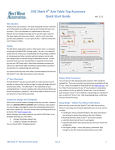
Integrated Systems
IR Sensor 1
PWM 1
Left Wheel
Servo
PWM 2
Right Wheel
Servo
IR Sensor 2
Bump
Sensors
Atmel ATmega323
(Me ga AVR- De ve lop me nt Board )
Voice
Dire ct 364
Port D0 and D1
UART
C MUc am
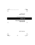
Figure 1. Integrated Systems of Chester
Chester is comprised of four main systems:
•
•
•
•
Object avoidance system
Voice recognition system
Human recognition system
Object dispensing sytem
Three of those systems are controlled by the onboard microcontroller. The
microcontroller I used for control was the Atmel AVR ATmega323.
EEL 5666
Fall 2002
Intelligent Machines Design Lab
Final Report
Page 7 of 38
12/13/2002
Following the KISS principle the object dispensing system was controlled by the
microcontroller. The human is able to dispense the objects he/she desires and notify the
robot via a voice command that they have taken what is desired from the robot.
The Object avoidance system is comprised of two Sharp GP2D12 IR detectors and bump
switches. The Vo ice recognition system is built upon the Voice Direct 364
(www.voiceactivation.com). Some of the features of the Voice Direct 364 (courtesy of
the www.sensoryinc.com) are
•
•
•
•
•
•
Seaker-Dependent and Continuous Listening speech
recognition technologies
Minimal external components
Recognizes up to 60 words or phrases in slave mode, or 15 in
stand-alone mode (broken in to 1, 2 or 3 sets)
Over 99% recognition accuracy with proper design
Phrase recognition up to 2.5 seconds
User- friendly speech prompting
The human recognizing system was achieved by using the CMUcam. The CMUcam is
capable of detecting and tracking bright colors. The camera detects a human by tracking a
brightly colored object placed next to the human requesting service from Chester.
Mobile Platform
For the mobile platform, I ended up modifying the Talrik Pro platform because of my
limited experience and to keep things as simple as possible. The platform is circular in
shape and is 9” in diameter. It rolls along on two Du-Bro 3” diameter wheels powered by
two hacked Futaba S3003 servos. Spanning across the center of the platform is a bridge
on which is mounted the voice kit and the CMU cam. A small bump skirt surrounds the
EEL 5666
Fall 2002
Intelligent Machines Design Lab
Final Report
Page 8 of 38
12/13/2002
platform and provides a contact mechanism with four bump switches placed strategically
around the periphery of platform. The gumball dispensing machine is placed on the rear
of the platform and is secured with velcro. A small caster wheel is mounted on the rear of
the platform. For power, I used 8 1700mAh NiMH batteries. The batteries were secured
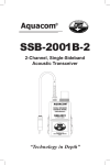
to the bottom of the platform with a velcro tie. Figures 2,3, and 4 show the layout of the
platform.
Figure 2. Rear view of Chester
EEL 5666
Fall 2002
Intelligent Machines Design Lab
Final Report
Figure 3. Bottom view of platform
Figure 4. Front view
Page 9 of 38
12/13/2002
EEL 5666
Fall 2002
Intelligent Machines Design Lab
Final Report
Page 10 of 38
12/13/2002
Actuation
For movement the robot rolls around on two 3” Du-Bro wheels that are powered by two
hacked Futaba S3003 servos connected to the ATmega323’s PWM channels.
Timer/Counter 1 was used to generate the PWM. Only two noticeable speeds were
generated by varying the PWM. castor wheel on the back provided support for the
platform, but it kept the robot from moving in a straight line. Perhaps a ping-pong ball or
something else would support the platform and not interfere with the direction trying to
be imposed by the movement of the wheels. I also had a problem with the hacked servos.
Initially they were calibrated to not move for a given PWM, but they eventually became
misaligned and would move slightly when given the stop PWM. The servos unfortunately
were glued to the platform and could not be removed. To compensate for this, I just
disabled the PWM whe never the robot came to a stop.
The CMUcam also has a servo port capable of using a servo to track a color. This could
add another level of actuation to the robot. However, this would add complexity to the
object tracking code so this feature was not used.
Sensors
There are four different types of sensors used in Chester.
1.) Infrared (IR) detectors
EEL 5666
Fall 2002
Intelligent Machines Design Lab
Final Report
Page 11 of 38
12/13/2002
2.) Voice Recognition
3.) Bump Switches
4.) Image Processing Camera – CMUcam
IR Sensors
Chester uses two Sharp GP2D12 IR detectors mounted on the top of the platform for
obstacle avoidance. The GP2D12 sensors measure distances of 4” to 30” and return an
analog voltage. The analog voltage from Chester’s IR sensors are sent to PortB0 and
PortB1, which are channels 0 and 1 of the Atmel ATMega323 A/D converter. The
analog voltage is then converted into a number between 0 and 255 and various decisions
can be made based on the converted values.
The IR detectors are placed at 15 degree angle inward and are placed on opposite sides of
the platform. For two IR sensors, this arrangement works well as Chester has been able to
avoid obstacles with the current obstacle avoidance routine that I have written. The only
problem I’ve had with this configuration is in the case when objects are not directly in
front of Chester, yet they are still in the path of the robot. In the current configuration of
the IR sensors it will not be possible for this situation to be detected. However, with the
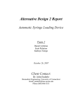
addition of a couple of bump sensors this problem can be eliminated. The following
diagram shows the placement of the IR detectors:
EEL 5666
Fall 2002
Intelligent Machines Design Lab
Final Report
Page 12 of 38
12/13/2002
Figure 1. IR Placement
There may be a more optimal placement of the IR sensors. I’ve been experimenting with
different configurations to see if it improves my obstacle avoidance algorithm.
Bump Sensors
Four bump switches are placed on the perimeter of Chester’s platform. These provide
another means of obstacle avoidance given that the IR sensors fail. The following is the
placement of the bump sensors on the platform.
EEL 5666
Fall 2002
Intelligent Machines Design Lab
Final Report
Page 13 of 38
12/13/2002
Front
Figure 2. Bump Switch placement on mobile platform.
To save analog ports, I used a voltage divider network and sent its output to Port B2 or
channel 2 of the a/d converter. Table 1 summarizes the different digital values for the
bump sensors and what they mean.
To make obstacle avoidance more robust, adding a left and right bump sensor may be
necessary.
Voice Recognition
EEL 5666
Fall 2002
Intelligent Machines Design Lab
Final Report
Page 14 of 38
12/13/2002
For voice recognition, I used the Voice Direct 364 (VD364) kit from Sensory Inc. The
kit has two main modes, slave mode and stand-alone mode. Slave mode allows the
microcontroller.to have complete control over the entire operation of the voice kit.
However, slave mode require that the voice kit use the Serial Peripheral Interface (SPI)
via a UART. This is problematic b/c the CMU cam will use the UART. In addition, the
complexity of programming for the voice kit is exponentially greater than stand-alone
mode.
Because of its simplicity, I’ve decided to use stand-alone mode for Chester. In standalone mode, there are three different options:
•
Speaker-Dependent
•
Single Word Continuous Listening
•
Multi Word Continuous Listening
Chester will use single word continuous listening. In this mode, the voice kit listens for a
single gateway word which will activate listening for any of 15 words which you can
train. When a word is recognized, it activates an output pin for one second. This output
will be a digital I/O on the Atmel chip and will be sampled by software to detect the
presence of a command.
EEL 5666
Fall 2002
Intelligent Machines Design Lab
Final Report
Page 15 of 38
12/13/2002
The circuitry for the voice circuit is very simple as can be found in the voice direct kit
manual. Using Protel, I have prototyped this circuit and mated it with the VD364 kit. The
following figure shows the final product.
Figure 6. Voice Circuit
One thing to note about the VD364, is the choice of word for the recognition set. The
performance of the kit depends highly upon what is chosen for a command set. The
manual recommends choosing words that sound dissimilar and that vary in syllables.
Also, intonation of the voice when training the kit is very important. I’ve had situation
where I trained a the kit in a monotone voice, but when I go to give it a command, I get
excited and change the intonation of my voice. The kit then has a hard time recognizing
the word as part of its command set.
EEL 5666
Fall 2002
Intelligent Machines Design Lab
Final Report
Page 16 of 38
12/13/2002
CMU Cam
Chester uses the CMUcam to find the human giving it the command. Using the CMU
Cam’s color tracking abilities, Chester will find the human which is giving it the
command. The CMUcam communicates with the Atmel microprocessor via the USART.
Using Codevision C compiler this is made easy. To send a command, you simply use the
printf() function. For example, to send put the camera into poll mode you would just
write the C code “printf(“PM 1\r”);” It is important, however to delay between
commands to give the camera ample time to return from a command. One thing to note
about Codevision is that the evaluation version is free, but if you want write larger
programs you’ll need the full version. Since the printf() command uses stdio.h, I ran into
this problem very late into the semester. Luckily, I was able to share a license with my
workplace. I probably would recommend sticking with GCC and AVR Studio unless you
are willing to pay $150 for a Codevision license.
Camera settings that were altered were polling mode and raw data mode.
The camera uses polling mode which sets the camera to send only one data packet back
after each command rather than a constant stream of data. Raw data mode is used to put
the returned data packets into raw data rather than printable ASCII characters. Raw data
mode is nice because it allows the data to be easily processed. The two main commands
that will be used are the Track Window (TW) and Track Color (TC) commands. TW used
with no arguments is used to adjust the camera to the color found at the center of the
tracking window. The data obtained from the TW command is sent to subsequent calls to
EEL 5666
Fall 2002
Intelligent Machines Design Lab
Final Report
Page 17 of 38
12/13/2002
TC with no arguments. The TC command returns a data packet which is then used to
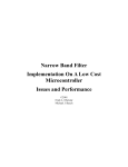
make decisions as to how to position the robot. The following is the structure of a packet
returned from TC.
The M indicates that the camera is returning a middle mass TC packet. Mx is the middle
mass x coordinate of the tracked region and My is the middle mass y coordinate. The
next four bytes give the coordinates of the tracked rectangle. Pixels is the # of pixels in
the tracked region capped at 255. Confidence indicates how well the camera has a lock on
the desired color. A confidence > 50 indicates a good lock, while a confidence < 10
indicates a poor lock.
Chester uses an interrupt service routine to periodically check the confidence level for
color tracking data and is able to determine if the colored object is nearby. For proximity
measurements, # of pixes will be used to determine if the object is close or far away to
Chester. Mx will be used to align the robot with the object and will keep the robot from
veering of to one side.
For more information, see the CMUcam user manual (http://www2.cs.cmu.edu/~cmucam/Downloads/CMUcamManual.pdf). It describes the entire serial
command set and what all the extrapolated data means.
EEL 5666
Fall 2002
Intelligent Machines Design Lab
Final Report
Page 18 of 38
12/13/2002
Experimental Layout and Results
The following PCB is what I used to connect the sensors to my microprocessor board:
First, I will discuss the tests I did on the IR sensors. To test the IR sensors I wrote a
program which would get data from the IR sensors and print them to the computer screen
EEL 5666
Fall 2002
Intelligent Machines Design Lab
Final Report
Page 19 of 38
12/13/2002
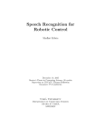
through the UART. I placed several different objects in front of Chester and read off the
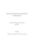
values of the IR sensors for different distances. I obtained the following results.
IR Readings for Shoe Object
140
Atmel A/D Reading
120
100
80
60
40
20
0
4
5
6
7.5 9.5
11
13
14
16 18.5 20
Distance (Inches)
23
25
Right IR Sensor
Left IR Sensor
EEL 5666
Fall 2002
Intelligent Machines Design Lab
Final Report
Page 20 of 38
12/13/2002
IR Readings for Box Object
140
Atmel A/D Values
120
100
80
Right IR Sensor
Left IR Sensor
60
40
20
21
24
.5
19
17
14
11
12
.5
8
9.5
7
5.5
3.5
4.5
0
Distance (Inches)
IR Readings for Dresser Object
120
Atmel A/D Value
100
80
Right IR Sensor
60
Left IR Sensor
40
20
0
4
5
7
9.5
11.5
14
16
Distance (Inches)
19.5 21.5
24
EEL 5666
Fall 2002
Intelligent Machines Design Lab
Final Report
Page 21 of 38
12/13/2002
The program used to test the IR sensors was also used to test the bump sensors. The code
for this program is provided in the appendices. The following voltage divider circuit was
used to distinguish between the different bump sensors.
The following table describes the analog values obtained for the different combinations
of bump switches.
Sensors Hit
Front
Back
Front Left
Front Right
Front and Front Left
Front and Front Right
Atmel A/D Value (+-1)
46
88
131
24
144
62
EEL 5666
Fall 2002
Intelligent Machines Design Lab
Final Report
Page 22 of 38
12/13/2002
For some of the bump switch combinations, the A/D reading would not stabilize at any
one value. Instead, it would toggle between the value +/- 1. This is probably because of
the lack of resolution for the A/D result. The A/D was configured for only 8 bits of
resolution and the bump sensors were sampled at 23 kHz.
The circuit used to test the voice kit is shown below.
EEL 5666
Fall 2002
Intelligent Machines Design Lab
Final Report
Page 23 of 38
12/13/2002
This circuit configures the voice chip for single word continuous listening mode. In this
mode, the circuit is continuously listening for the gateway word. Once the gateway word
is spoken, the voice kit listens for any of 15 different words. To test this configuration, I
trained the word “Chester” for the continuous listening and trained the speaker dependent
words “come here” and “go away”. These I trained at three different distances and then I
tested the recognition accuracy at various positions. The results of these tests are given by
the following table.
Training Distance Accuracy at 3 ft
3ft
70 %
6ft
60 %
9ft
40%
12ft
30%
Note: Accuracy based on 10 trials
Accuracy at 6 ft
60%
70%
40%
30%
Accuracy at 9ft
60%
50 %
60%
40%
Accuracy at 12 ft
40%
40%
50%
50%
The CMUcam comes with a Graphical User Interface written in Java. Using this interface
I tested the various capabilities of the camera. I was able to track various colored object
such as my hand and a blue ball. The camera also dumped the mean color and the
variance. Dumping frames is also possible and I used this feature to properly focus the
lens.
Once I had the camera in focus, and was able to see data with the CMUcamGUI I began
interfacing the camera with the microprocessor board. To interface the CMUcam, I found
EEL 5666
Fall 2002
Intelligent Machines Design Lab
Final Report
Page 24 of 38
12/13/2002
that removing the max232 chip and taking non- level shifted serial data from the camera
to the non- level shifted pins of the ATMega323 worked the best.
The following psuedocode is what I used to test the CMUcam:
Reset CMUcam
Put camera into poll mode and turn on raw data mode for returned packets from camera
Call Track Window
LOOP_START
Call Track Color
If # of Pixels > 250 And Confidence > 50 The n Go Backward
If Middle Mass X > 55 And Confidence> 25 Then Go Right
If Middle Mass X< 35 And Confidence > 25 Then Go Left
If # of Pixels < 120 And Confidence > 25 Then Go Fwd
GOTO LOOP START
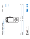
To test this algorithm I used the setup shown in the image below:
What I discovered when testing this code was that lighting is vital to the success of the
CMUcam. Standard incandescent lighbulbs worked ok, but florescent lighting such as
that in the lab works much better. In the lab environment, Chester recognizes objects
EEL 5666
Fall 2002
Intelligent Machines Design Lab
Final Report
Page 25 of 38
12/13/2002
from 7-9 feet away while in my apartment Chester will recognize objects from only 3-5
feet away. These results were much better than several other people in the class perhaps
b/c I bought my camera from Acroname rather than Seattle Robotics. The camera from
Acroname comes with an IR filter already installed while I believe it’s a special order
from Seattle Robotics.
Behaviors
Chester will perform the following behaviors:
•
Listening behavior
•
Obstacle avoidance behavior / human tracking behavior
•
Human tracking behavior
•
Dispensing / pause nehavior
•
Ball chasing behavior
The following flow-chart relates all the behaviors and gives an overview of the
operation of Chester:
EEL 5666
Fall 2002
Intelligent Machines Design Lab
Final Report
Page 26 of 38
12/13/2002
Listening For Serve
Command
Initial State
Serve
Command?
N
Y
Human Finding /
Obstacle Avoidance
Human
Found?
N
N
Y
Serve human and
wait for voice
command
Chase
Command
Leave
Command
Y
Ball Chase
Behavior
Listening behavior
When Chester is first turned on it will immediately enter listening behavior. In this state,
Chester is awaiting a voice command to commence serving. Once the human gives the
voice command to serve, Chester will enter Obstacle Avoidance / Human tracking
behavior. While in this behavio r, Chester is calibrated to his environment. To calibrate
the camera, the object to be tracked is placed about 5 inches away from the CMUcam.
EEL 5666
Fall 2002
Intelligent Machines Design Lab
Final Report
Page 27 of 38
12/13/2002
The rear bumper is then pressed and the camera captures the color of the object with the
track window command. It is also very important in this behavior to train the voice sensor
to the environment that it will be used in. If the voice sensor is not trained the robot likely
will not operate properly.
Obstacle Avoidance / Human tracking behavior
The obstacle avoidance behavior was taken from Eric Donnelly’s WOMAN Robot final
report Spring 2002. The algorithm, based on random numbers, seemingly gives the robot
a mind of its own when avoiding obstacles. Chester will turn in random directions at
random speeds for random amounts of time. This makes the robot more interesting and
gives the robot better coverage of an area. While in obstacle avoidance mode, Chester’s
senses are checked in a priority fashion. The following is the order of priority from
highest to least:
•
Object Tracking
•
Bump Switches
•
IR Detectors
While Chester is in obstacle avoidance mode, he is collecting data from the IR detectors
and bump sensors to avoid obstacles. Meanwhile, Chester uses the CMUcam to try to
track the brightly colored object placed at the feet of the human. If the object is not
immediately visible to Chester, he will turn 360 degrees looking for the object. If Chester
still does not see the object, he will move in a random pattern around the room and then
EEL 5666
Fall 2002
Intelligent Machines Design Lab
Final Report
Page 28 of 38
12/13/2002
spin in place again looking for the object. This will continue until Chester finds the
desired object.
Once Chester locates the object, he will move towards the object until he reaches a
certain distance. Once Chester has reached the desired distance from the brightly colored
object he will enter the dispensing / pause behavior. In this behavior, Chester rotates 180
degrees and aligns the gumball machine with the tracked object.
Dispensing / pause behavior
In this behavior, the robot will be positioned in front of the brightly colored object. The
human can now dispense the gumballs from the robot at his/her leisure. Once the human
has been served, he /she gives Chester either the leave command or the ball chase
command. If the ball chase command is given, Chester turns around faces the ball and
will chase the ball around.
Ball Chasing Behavior
In this behavior, Chester will turn around and face the ball or object and will follow the
object as long as the object is held in view of the camera tracking window.
Conclusion
This concludes my final report for Chester the autonomous waiter robot. The robot
worked as specified and was a success. This project has given me the confidence to
EEL 5666
Fall 2002
Intelligent Machines Design Lab
Final Report
Page 29 of 38
12/13/2002
pursue other projects and I now feel well equipped to solve more difficult engineering
problems.
Appendices
The following is the final version of the code for Chester. The program was written using
CodevisionAVR C compiler:
/*********************************************
Project : Chester Final Code
Version : 3.0
Date : 12/05/2002
Author : David Winkler
Chip type
: ATmega323
Clock frequency : 6.000000 MHz
Internal SRAM size : 2048
External SRAM size : 0
Data Stack size : 512
*********************************************/
/******************************************
Trying to get the robot to spin in place to look for red ball...
also attempting to get the robot to stop once it thinks it finds the ball,
spin in place and then back up towards ball to dispense gumballs
*******************************************/
// INCLUDES
#include <mega323.h>
#include <delay.h>
#include <stdio.h>
// CONSTANTS
#define ADC_VREF_TYPE 0xE0
#define L_EYE_TOLERANCE 50
#define R_EYE_TOLERANCE 50
#define FIRST_ADC_INPUT 0
#define LAST_ADC_INPUT 4
#define BACK_BUMP 88
#define FLEFT_BUMP 131
EEL 5666
Fall 2002
Intelligent Machines Design Lab
Final Report
#define FRIGHT_BUMP 24
#define CENTER_BUMP 46
// GLOBAL VARIABLES
unsigned int adc_data[LAST_ADC_INPUT-FIRST_ADC_INPUT+1];
unsigned int count=5;
short int speed_temp_l=0;
short int speed_temp_r=0;
short int speed_val_l=0;
short int speed_val_r=0;
int temp;
bit sense=0;
bit initiated=0;
unsigned char random_num;
unsigned char cpacket[10];
bit homelock=0;
int count1=0;
bit camera_init=0;
bit ball_chasing=0;
bit stopped=0;
bit skip=0;
void check_ir(void);
void drive(int,int);
int random(char);
void bumper(void);
void disable_pwm()
{
TCCR1A=0x01;
}
void enable_pwm()
{
TCCR1A=0xA1;
}
void check_camera(void)
{
PORTC.0=0;
count1=0;
printf("TC\r");
Page 30 of 38
12/13/2002
EEL 5666
Fall 2002
Intelligent Machines Design Lab
Final Report
while (count1<11) {
cpacket[count1]=getchar();
count1++;
}
PORTC.0=1;
if (cpacket[9]>40) homelock=1;
if (homelock)
{
// 45 is H center
if (cpacket[8] > 250 && cpacket[9] > 50) {
drive(-1,-1);
if (!ball_chasing)
{
delay_ms(300);
drive(-1,1);
delay_ms(1600);
drive(-1,-1);
delay_ms(400);
drive(0,0);
delay_ms(10);
disable_pwm();
stopped=1;
} // robot stops and waits for voice command
else {
delay_ms(300);
drive(0,0);
delay_ms(10);
disable_pwm();
}
}
if (cpacket[2] > 55 && cpacket[9] > 25) drive(0,1); //Right
if (cpacket[2] < 35 && cpacket[9] > 25) drive(1,0); //Left
if (cpacket[8] < 120 && cpacket[9] > 25)drive(1,1); //Fwd
if (cpacket[9] <=25 && !skip) {
drive(0,0); //Stop
delay_ms(10);
disable_pwm();
}
}
delay_ms(25);
}
// Timer 1 overflow interrupt service routine
interrupt [TIM1_OVF] void timer1_ovf_isr(void)
{
Page 31 of 38
12/13/2002
EEL 5666
Fall 2002
Intelligent Machines Design Lab
Final Report
if (!camera_init || !initiated) return;
if (count--==0) {
check_camera();
if (homelock) {
count=3;
return;
}
check_ir();
bumper();
if (sense==1) {
drive(speed_temp_l,speed_temp_r);
delay_ms(175*(random(7)+2));
sense=0;
}
count=3;
}
}
#pragma savereginterrupt [ADC_INT] void adc_isr(void)
{
#asm
push r26
push r27
push r30
push r31
in r30,sreg
push r30
#endasm
register static unsigned char input_index=0;
// Read the AD conversion result
adc_data[input_index]=ADCH;
// Select next ADC input
if (++input_index > (LAST_ADC_INPUT-FIRST_ADC_INPUT))
input_index=0;
ADMUX=(FIRST_ADC_INPUT|ADC_VREF_TYPE)+input_index;
// Start the AD conversion
ADCSR|=0x40;
#asm
pop r30
out sreg,r30
pop r31
pop r30
Page 32 of 38
12/13/2002
EEL 5666
Fall 2002
Intelligent Machines Design Lab
Final Report
pop r27
pop r26
#endasm
}
/************************************************
Function: drive
Inputs: Two integers between -2 and 2 representing
the speed of the motors. A speed > 0 is forward,
while a speed < 0 is backward. The greater the
magnitude of the inputs the faster the motors will
turn.
Outputs: none
Notes: A 100 ms delay is implemented when changing
motor speeds to protect the motors from burnout.
************************************************/
void drive(short int speedl, short int speedr){
enable_pwm();
if(speedl > 2) //can't overdrive servos
speedl =2; //.8 sec max total to change speeds
if(speedl < -2)
speedl = -2;
if(speedr > 2)
speedr = 2;
if(speedr < -2)
speedr = -2;
while(speed_val_l != speedl || speed_val_r != speedr){
if(speed_val_l > speedl){
OCR1BL = OCR1BL -1;
speed_val_l--;
}
if(speed_val_l < speedl){
OCR1BL = OCR1BL +1;
speed_val_l++;
}
if(speed_val_r > speedr){
OCR1AL = OCR1AL +1;
speed_val_r--;
}
if(speed_val_r < speedr){
OCR1AL = OCR1AL -1;
speed_val_r++;
}
delay_ms(25); //delay on each increment to protect motors
}
Page 33 of 38
12/13/2002
EEL 5666
Fall 2002
Intelligent Machines Design Lab
Final Report
Page 34 of 38
12/13/2002
}
int random(unsigned char range){
//generates random numbers between 0-254
range++;
return TCNT0 % range;
}
void check_ir(void){
if(adc_data[1] > L_EYE_TOLERANCE || adc_data[0] >
R_EYE_TOLERANCE){
sense = 1;
temp= random(3) - 2; // random speed between -2 and 1
if(adc_data[1] > adc_data[0] + 10) {
speed_temp_l= temp;
speed_temp_r= temp + random(3)+1; // always point away from
obstacle
}
else if(adc_data[0] > adc_data[1] + 10) {
speed_temp_l= temp + random(3)+1;
speed_temp_r= temp; //always point away from obstacle
}
else {
speed_temp_l = random(4) -2; // straight ahead turn in place
speed_temp_r = -speed_temp_l;
}
}
}
void bumper(void){
if(adc_data[2]==0 || adc_data[2]==1) return;
sense =1;
while(1){
if(adc_data[2]==45 || adc_data[2]==46 || adc_data[2]==47 ||
adc_data[2]==143 || adc_data[2]==144 || adc_data[2]==145 ||
adc_data[2]==61 || adc_data[2]==62 || adc_data[2]==63){ //front
drive(-1, -1); //back up
delay_ms(300);
speed_temp_l = random(4) -2; //turn in place if straight
speed_temp_r = -speed_temp_l; //forward
break;
}
else if(adc_data[2]==130 || adc_data[2]==131 || adc_data[2]==132){ //left
front
speed_temp_l= -1; //right will reverse harder
EEL 5666
Fall 2002
Intelligent Machines Design Lab
Final Report
Page 35 of 38
12/13/2002
speed_temp_r= -2;
break;
}
else if(adc_data[2]==23 || adc_data[2]==24 || adc_data[2]==25){ //right
front
speed_temp_r= -1; //left will reverse harder
speed_temp_l= -2;
break;
}
else if(adc_data[2]==87 || adc_data[2]==88 || adc_data[2]==89){
//forward!!
speed_temp_r= random(1)+1;
speed_temp_l= random(1) +1;
break;
}
else return;
}
}
/*********************************************
Function: chester_init()
Input: None
Output: None
Purpose: Set up A/D, I/O Ports, UART, Interrupts, and Timers
**********************************************/
void chester_init(void)
{
// Input/Output Ports initialization
// Port A initialization
PORTA=0x00;
DDRA=0x00;
// Port B initialization
PORTB=0x00;
DDRB=0x00;
// Port C initialization
PORTC=0x00;
DDRC=0xFF;
// Port D initialization
PORTD=0x00;
DDRD=0x30;
EEL 5666
Fall 2002
Intelligent Machines Design Lab
Final Report
// Timer/Counter 0 initialization
// Clock source: System Clock
TCCR0=0x01;
TCNT0=0x00;
// Timer/Counter 1 initialization
// Clock source: System Clock
// Clock value: 23.438 kHz
// Mode: Ph. correct PWM top=00FFh
// OC1A and OC1B output: Non-Inverted
// Input Capture on Falling Edge
TCCR1A=0xA1;
TCCR1B=0x04;
TCNT1H=0x00;
TCNT1L=0x00;
OCR1AH=0x00;
OCR1AL=0x18;
OCR1BH=0x00;
OCR1BL=0x18;
// Timer 1 Overflow Interrupt Enabled
TIMSK=0x04;
// USART initialization
// Communication Parameters: 8 Data, 1 Stop, No Parity
// USART Receiver: On; USART Transmitter: On
// USART Mode: Asynchronous; USART Baud rate: 9600
UCSRA=0x00;
UCSRB=0x18;
UCSRC=0x86;
UBRRL=0x26;
UBRRH=0x00;
// Analog Comparator initialization (Unused)
ACSR=0x80;
SFIOR=0x00;
// ADC initialization
// ADC Clock frequency: 93.750 kHz
// ADC Voltage Reference: AREF pin (Internal 2.56 V)
// Only the 8 most significant bits of
// the AD conversion result are used
ADMUX=ADC_VREF_TYPE;
ADCSR=0xCE;
Page 36 of 38
12/13/2002
EEL 5666
Fall 2002
Intelligent Machines Design Lab
Final Report
Page 37 of 38
12/13/2002
}
// GLOBAL VARIABLES
void init_camera(void)
{
printf("RS\r");
delay_ms(100);
printf("\r");
delay_ms(100);
printf("PM 1\r");
delay_ms(100);
printf("RM 3\r");
delay_ms(5000);
while(adc_data[2]!=88);
while (UCSRA.7) temp=UDR; //flush the receive buffer
printf("TW \r");
delay_ms(2000);
while(adc_data[2]!=88); // wait for back bumper press to begin
camera_init=1;
PORTC=~PORTC;
while (UCSRA.7) temp=UDR; //flush the receive buffer
}
void main(void)
{
// LOCAL Variables
chester_init(); // Initialize A/D, timers, interrupts, and USART
disable_pwm();
delay_ms(1500); // Delay to give the A/D and other systems a chance to warm- up
#asm("sei")
init_camera();
while (adc_data[3]<0xE0){} // Wait until voice command given
initiated=1;
drive(-1, 1); //begin moving
delay_ms(1000);
while (1) {
EEL 5666
Fall 2002
//
random_num=random(50);
while(random_num-- != 0 && !homelock){
drive(2,2);
delay_ms(100);
}
if (!homelock) {
drive(random(4)-2, random(4)-2); //change directions
drive(-1,1); // spin in place looking for objec
random_num = random(15);
}
while(random_num-- != 0 && !homelock) delay_ms(100);
if (stopped==1) {
while (adc_data[3]<0xE0 && adc_data[4]<0xE0) {};
stopped=0;
if (adc_data[3]>=0xE0) {
homelock=0;
drive(1,-1);
delay_ms(1000);
}
else if (adc_data[4]>=0xE0) {
skip=1;
ball_chasing=1;
drive(2,2);
delay_ms(400);
drive(1,-1);
delay_ms(400);
drive(0,0);
skip=0;
}
}
}
}
Intelligent Machines Design Lab
Final Report
Page 38 of 38
12/13/2002