1
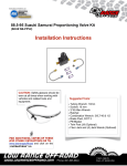
Installation and User’s Manual GF1081 V1.5 Jr. Starter Kit – JR100 www.PipeBurstPro.com 800-246-LEAK (5325) Congratulations on your new PipeBurst Pro Automatic Water Protection System! Please visit www.PipeBurstPro.com for new component and troubleshooting information. Table of Contents INSTALLATION .................................................................................................... 3 I. Tool Requirements .................................................................................... 3 II. Mounting & Initial Startup Instructions ................................................... 3 SETUP AND OPERATION.................................................................................... 4 I. VIP Jr. (Valve Interface Panel Jr.) ............................................................. 4 A. Component Description .......................................................................... 4 B. Operation Instructions ............................................................................. 4 C. Integration with Security Systems ........................................................... 5 II. SideKick ...................................................................................................... 5 A. Component Description ...................................................................................5 B. Operational Instructions ..................................................................................5 C. Water Sensor Placement ................................................................................6 III. FloTrol ......................................................................................................... 7 A. Component Description ...................................................................................7 B. Operational Instructions ..................................................................................7 IV. Base Hardwire Kit ................................................................................................8 A. Component Description ...................................................................................8 B. Installation .........................................................................................................8 ANNUAL MAINTENANCE .................................................................................... 9 I. Cleaning ...................................................................................................... 9 II. Testing ........................................................................................................ 9 III. Annual Maintenance Agreement ............................................................... 9 2|Page Installation Tool Requirements I. These tool requirements assume the TickerValve is already installed by an authorized PipeBurst Pro dealer or a licensed plumber. Electric drill, drill bits, and screwdriver tips to mount the devices. Philips #1 or #2 hand screw driver. II. Mounting & Initial Startup Instructions EXTREMELY IMPORTANT: INSTALL TICKERVALVE AFTER ALL FIRE SUPPRESSION LINES THAT MAY BE IN PLACE FOR THE FACILITY. 1. 2. 3. 4. 5. Use an authorized PipeBurst Pro dealer or a licensed plumber to install the TickerValve in the building. Ensure proper placement of the valve, we recommend placing this on the water main coming into the building for whole building protection. Position the VIP Jr. (Valve Interface Panel Jr.) Verify that the TickerValve wires, SideKick, and the AC adapter will Common TickerValve Installation reach the VIP Jr., floor, and AC outlet respectively. If a FloTrol or Base Hardwire Kit is going to be used, before mounting the VIP Jr. Remove the back cover and wire them up according to their instructions. Wire the security system to the VIP Jr. at this time, if security system integration is desired. Hold the VIP Jr. to the wall and mark the 2 mounting holes on wall, then attach the VIP Jr. to wall with proper mounting hardware (not included). Plug in AC adapter to standard 120VAC wall outlet. A battery backup, similar to those used on computer systems, may be used for 6. uninterrupted protection. The basic system is now installed. See Setup and Operation to continue complete installation of the PipeBurst Pro Jr. 3|Page Setup and Operation VIP Jr. (Valve Interface Panel Jr.) I. A. Component Description 1. The VIP Jr. is the main controller for the PipeBurst Pro Jr. It includes a 20 foot SideKick, basic operational instructions via its label, 1 button, 2 LED’s, and an audible alarm. 2. The button requires a tap to initiate the given action depending on the state of the VIP Jr. 3. LED’s, are also designated by the “WATER OFF” for the red LED, and “WATER ON” for the green LED. 4. Audible sounds also signal changes in system conditions. 5. VIP Jr. will test TickerValve monthly. 6. VIP Jr. can have additional water sensors wired to it via the Base Hardwire Kit. B. VIP Jr. Part #: VJ100 Operation Instructions 1. Button 1 – WATER ON / OFF ( LED Color Green Red Red with Alarm ) Definition Water On Water Off Alarm a. TURN WATER ON / OFF: Tap Button 1 to turn ON or OFF the WATER. b. DURING ALARM: Tap Button 1 to SILENCE the audible ALARM. Tap Button 1 again to RESET the VIP Jr. ALARM. If a water sensor is wet when trying to reset the system the system will not open the TickerValve. System sensors MUST be dry to reset the system. 4|Page C. Integration with Security Systems 1. On the circuit board on the back of the VIP Jr. there is a terminal block labeled CN1. a. CN1 – This relay switches when an alarm condition occurs allowing your security system to alert your monitoring service. Normally Open – NO Common – C Normally Closed – NC b. These contacts are rated for 1A 24VDC or 1A 120VAC resistive loads. c. Remove any necessary knockout slots with a utility knife, and thread the wires from the alarm panel through the knockout slot openings of the VIP Jr. case and connect to the CN1 terminal block as Security System Interface required. Terminal Block d. Consult the security system installation instructions, and/or the company that installed the system to best integrate the PipeBurst Pro Jr. with security systems. II. SideKick A. Component Description 1. The SideKick is a water protection device. 2. When the SideKick detects water via the gold plated sensors the SideKick will send a wireless signal to the VIP Jr. This will tell the VIP Jr. to close the TickerValve and the VIP Jr. will produce an audible alarm. B. Operational Instructions 1. Place SideKick in the desired location for the install. See Section II.C. (Water Sensor Placement) for considerations and recommendations on this process. 2. Test SideKick in the final installation location by wetting the sensor. SideKick Part #: SK100B or SK120B 5|Page C. Water Sensor Placement 1. Truly irreplaceable items are not really insurable; insurance policies may replace them with money, which will never capture the real value. With this in mind, it is ultimately up to the user to determine how many FloodBugs is needed and where they should be placed. 2. Considerations and Recommendations: a. The exact number and location of FloodBugs installed depends on the desired level of protection, generally, more sensors create a greater coverage area and leads to a quicker response to a potentially damaging leak. b. Remember the FloodBug with a SideKick can potentially cover two leak sources, for example; place the FloodBug under the kitchen sink and the attached SideKick under the dishwasher. c. Place the FloodBug and SideKick near any potential leak source. d. If a specific area of the facility has extreme costs for repair or replacement, or that area contains irreplaceable items, placement of multiple sensors should be considered in this area to stop the water before any damage can occur. e. Water must reach the sensors to activate the system. Consider how level the floor is, and potential water flow paths; then place the sensors accordingly. The system will not have the quick response desired if the sensors are placed on high spots or shielded from the flow of water. f. At a minimum, it is recommended to have one sensor on each facility floor. g. Water detection devices are not recommended for use in high humidity areas. 6|Page III. FloTrol A. Component Description 1. The FloTrol is an optional hardwired remote control switch used to operate the TickerValve and indicate the system state with two LED’s and an audible alarm. B. FloTrol Part #: FL100 Operational Instructions 1. Button 1 – WATER ON / OFF ( LED Color Green Red Red with Alarm ) Definition Water On Water Off Alarm a. TURN WATER ON / OFF: Tap Button 1 to turn ON or OFF the WATER. b. DURING ALARM: Tap Button 1 to SILENCE the audible ALARM. Tap Button 1 again to RESET the VIP Jr. ALARM. If a water sensor is wet when trying to reset the system the system will not open the TickerValve. System sensors MUST be dry to reset the system. C. Installation 1. Remove the four screws and the back cover from the FloTrol. 2. Remove the necessary knockout slots with the utility knife and feed 5 conductor solid strand thermostat control wire (not included) through to the “FLOTROL” terminal block. 5 wires are required to make the necessary connections. 3. Connect the control wire to the “FLOTROL” terminal block on both the VIP Jr. and FloTrol circuit boards. VIP Jr. To FloTrol Terminals 1 through 5 must be connected. Wire Terminal Block terminal 1 to 1, 2 to 2, 3 to 3, 4 to 4, and 5 to 5. Terminal 6 is not in use. 4. Use the open holes located on the left and right side of the case to mount the FloTrol. Note: Hardware not included. 7|Page IV. Base Hardwire Kit A. Component Description 1. The Base Hardwire Kit includes an Adapter Wire, Junction Box, 5 Wall Jacks, 2 SideKick Splitters and 5 SideKicks. 2. This option allows the user to expand coverage to multiple locations throughout the facility. B. Installation 1. Use the recommended Wiring Cable (GF1138) for wiring of Base Hardwire Kit. Base Hardwire Kit Part #: PB300B or PB300W 2. Remove the back cover of the VIP Jr. and locate the jack labeled “SIDEKICK SENSOR”. Unplug the SideKick and plug in the SideKick Splitter, then plug the SideKick back into the Splitter as well as the Adapter Wire. Replace the back cover on the VIP Jr. 3. Mount the Junction Box securely as desired and plug in the Adapter Wire. 4. Run the home run Wiring Cable (GF1138) throughout the facility to gain the greatest protective coverage area. 5. Mount the Wall Jack plates and terminate the home run Wiring Cable under each respective terminal. 6. Terminate the other end of the home run cable wires under respective terminals in the Junction Box and fasten securely. Place no more than 5 home run cable wires under each terminal in the Junction Box. If there are more than 5 home run cables, the Wiring Center (GF9030) will be needed to complete installation. See www.PipeBurstPro.com for more information on the Wiring Center. 7. Fully insert each SideKick connector into the Wall Jack; there should be no movement in or out when the wire is pulled and pushed. 8. Test each SideKick by placing a small amount of water between the gold sensor pads, once system is completely set up. The VIP Jr. should close the TickerValve and signal with an audible alarm, if it does not; check the connections at the wall jack, Wiring Center, and Junction Box to ensure proper wiring. 8|Page Annual Maintenance Cleaning I. A. B. Annual system cleaning is recommended to ensure proper operation. Cleaning the SideKicks with a wet towel accomplishes many tasks at once. The cleaning keeps the gold sense pads free of any dirt, debris, or other material that may inhibit the detection of water. II. Testing A. Annual system testing is recommended to ensure proper operation of the system. III. Annual Maintenance Agreement A. The local PipeBurst Pro Dealer may offer an Annual Maintenance Agreement to annually perform the above tasks and more. Check with your local PipeBurst Pro Dealer for details. 9|Page Customer Support: GreenField Direct, LLC 14015 238th Street Greenwood, NE 68366 http://www.pipeburstpro.com/contact/ Phone: 800-246-LEAK (5325) Fax: (402) 944-2907 E-Mail: [email protected] Operating Hours: Monday - Friday, 7:00am - 6:00pm CST (Excludes Major Holidays) Warranty - PipeBurst Pro Products 7 Year Limited Warranty - GreenField Direct, LLC of 14015 238th St, Greenwood, NE 68366 (“Warrantor”), warrants to the original purchaser and installed location of the PipeBurst Pro, manufactured by Warrantor, and to any person to whom such originally installed equipment is transferred to via the transfer of said real property that original installation was made, that such equipment shall be free from defects in materials and workmanship during a two (2) year period; additionally the electric valve actuator enclosure and its’ electronic components inside, shall be free from interior moisture damage for a period of seven (7) years; both periods commencing upon the receipt of order date for such equipment from the original purchaser thereof; (the “warranty periods”). Product should be registered to be covered by warranty. Note: Please register the PipeBurst Pro to activate your warranty http://www.pipeburstpro.com/support/warranty-registration/ FCC Disclaimer - This equipment has been tested and found to comply with the limits for a Class B digital device, pursuant to part 15 of the FCC Rules. These limits are designed to provide reasonable protection against harmful interference in a residential installation. This equipment generates, uses and can radiate radio frequency energy and, if not installed and used in accordance with the instructions, may cause harmful interference to radio communications. However, there is no guarantee that interference will not occur in a particular installation. If this equipment does cause harmful interference to radio or television reception, which can be determined by turning the equipment off and on, the user is encouraged to try to correct the interference by one or more of the following measures: Reorient or relocate the receiving antenna. Increase the separation between the equipment and receiver. Connect the equipment into an outlet on a circuit different from that to which the receiver is connected. Consult the dealer or an experienced radio/TV technician for help. Modifications not expressly approved by the manufacturer could void the user's authority to operate the equipment under FCC rules. Power Requirements: For Indoor Use Only (Except TickerValve) Requirements for US & Canada Use supplied AC Adapter Input Output VIP Jr. 100-240V ~50/60Hz 1.0A MAX 18V DC 2.22A 10 | P a g e Notes: Maintenance Record: 11 | P a g e www.PipeBurstPro.com 800-246-LEAK (5325) 12 | P a g e