1
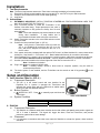
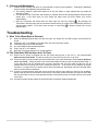
Installation and User’s Manual V1.0 www.PipeBurstPro.com 800‐246‐LEAK (5325) Congratulations on the purchase of your new PipeBurst Pro Jr. Flood Control System! Please visit www.PipeBurstPro.com for new components, features, tips and tricks and troubleshooting information. Table of Contents Installation .................................................................................................................................................. 3 1. Tool Requirements ........................................................................................................................................... 3 2. Instructions ........................................................................................................................................................ 3 Setup and Operation ................................................................................................................................ 3 3. Valve Interface Panel Jr. (VIP Jr.) ................................................................................................................. 3 3.1. Component Description ............................................................................................................................. 3 3.2. Button Function ........................................................................................................................................... 3 3.3. System Condition ........................................................................................................................................ 3 4. SideKick .............................................................................................................................................................. 3 4.1. Component Description ............................................................................................................................. 3 4.2. Placement .................................................................................................................................................... 3 5. FloTrol ................................................................................................................................................................. 4 5.1. Component Description ............................................................................................................................. 4 5.2. Installation .................................................................................................................................................... 4 5.3. Button Function ........................................................................................................................................... 4 5.4. System Condition ........................................................................................................................................ 4 6. Optional Base Hardwire Kit............................................................................................................................ 4 6.1. Component Description ............................................................................................................................. 4 6.2. Installation .................................................................................................................................................... 5 7. Security System Interface .............................................................................................................................. 5 7.1. Component Description ............................................................................................................................. 5 7.2. Installation .................................................................................................................................................... 5 8. Cleaning and Maintenance ............................................................................................................................. 6 Troubleshooting ....................................................................................................................................... 6 9. What To Do When Water Is Detected .......................................................................................................... 6 10. The TickerValve Will Not Open And / Or Close ..................................................................................... 6 2|Page Installation 1. Tool Requirements Note: 1.1. 1.2. 1.3. These tool requirements assume the TickerValve is already installed by a licensed plumber. Electric drill, drill bits, and screwdriver tips to mount the VIP Jr. and FloTrol to your wall as desired. Philips #1 or #2 hand screw driver for final hand tightening. Utility knife. 2. Instructions 2.1. 2.2. 2.3. 2.4. 2.5. 2.6. 2.7. 2.8. 2.9. EXTREMELY IMPORTANT: INSTALL TICKERVALVE AFTER ALL FIRE SUPPRESSION LINES THAT MAY BE IN PLACE FOR THE FACILLITY. Use a licensed plumber to install the TickerValve in the facilities’ inlet water line(s). Proper placement of the valve is extremely important to fully protect the facility from fire and water damage. Note: Insure that adequate pipe thread sealant is used during valve installation. A soap bubble test is recommended to detect leaks at the pipe connections. Attach TickerValve actuator to the valve head and secure with 2 nuts provided. Position the Valve Interface Panel Jr. (VIP Jr.). Note: Verify that the TickerValve wires will reach the VIP Jr., the SideKick will reach from the VIP Jr. to the Common TickerValve Installation floor, and the AC adapter will reach from the VIP Jr. to the AC outlet. If the system has been purchased with the optional FloTrol and / or Base Hardwire Kit, connect those wires at this time. See Section 5 – FloTrol and / or 6 – Base Hardwire Kit Security for connection information. If the PipeBurst Pro Jr. system is to be connected to a security system, make those connections at this time. See section Error! Reference source not found. – Security System Interface for connection information. Use the open holes located on the left and right side of the case to mount the VIP Jr. Note: Hardware not included Plug in AC adapter to standard 120VAC outlet. Note: A battery backup, similar to those used on computer systems, may be used for uninterrupted protection. The basic system is now installed, and the TickerValve can be turned on and off by pressing on the keypad. Setup and Operation 3. Valve Interface Panel Jr. (VIP Jr.) 3.1. Component Description a. The VIP Jr. is the central control and user interface for the PipeBurst Pro Jr. system. It operates the TickerValve and indicates the system state with two LEDs and an audible alarm. Shown here with the attached SideKick. 3.2. Button Function a. 3.3. WATER ON / OFF: Press TickerValve. to manually open and close the VIP Jr. with SideKick System Condition WATER ON WATER OFF WATER DETECTED Green LED Red LED Red LED and Audible Alarm 4. SideKick 4.1. Component Description a. The SideKick is a stainless steel water detection device that utilizes gold plated sense pads to signal the VIP Jr. if water is detected. This signal will, trigger the alarm, close the TickerValve, and provide protection against further water damage. 4.2. Placement a. It is important to remember that water must reach the SideKick to activate the system, these locations should be: 3|Page 1. Clean and free of dirt and debris. 2. The lowest point in the flow path of potential water leaks. The system will not have the quick response desired if the sensors are placed on high spots or shielded from the flow of water. 3. On a hard smooth surface, if possible. Absorbent surfaces such as carpet will potentially increase the amount of water and time needed for the SideKick to react and send the signal to close the TickerValve. b. Test each SideKick by placing a small amount of water between the gold sense pads. The VIP Jr. should close the TickerValve and signal with an audible alarm. Note: SideKick must be dried out after testing before resetting of the system is possible. 5. FloTrol 5.1. Component Description a. The FloTrol is an optional hardwired remote control switch used to operate the TickerValve and indicate the system state with two LEDs and an audible alarm. While the exterior appearance of the FloTrol looks similar to the VIP Jr. the interior components are different inside. 5.2. Installation a. Remove the four screws and the back cover from the FloTrol. b. Remove the necessary knockout slots with the utility knife and feed 5 conductor solid strand thermostat control wire (not included) through to the “FLOTROL” terminal block. 5 wires are required to make the necessary connections. c. Connect the control wire to the “FLOTROL” terminal block on both the VIP Jr. and FloTrol circuit boards. Terminals 1 through 5 must be connected. Wire terminal 1 to 1, 2 to 2, 3 to 3, 4 to 4, and 5 to 5. Terminal 6 is not in use d. Use the open holes located on the left and right side of the case to mount the FloTrol. Note: Hardware not included 5.3. Button Function a. 5.4. FloTrol WATER ON / OFF: TickerValve. Press to manually open and close the System Condition WATER ON WATER OFF WATER DETECTED Green LED Red LED Red LED and Audible Alarm VIP Jr. To FloTrol Terminal Block (VIP Jr. Rear View) 6. Optional Base Hardwire Kit 6.1. Component Description a. The Base Hardwire Kit includes an Adapter Jack, 5 Wall Jacks, and 5 SideKicks. b. This option allows the user to expand coverage to multiple locations throughout the facility. c. Considerations and Recommendations 1. Generally, more sensors create a greater coverage area and leads to a quicker response to a potentially damaging leak. 2. Place the SideKick near any potential leak source. Some Junction Box Adapter Jack common appliances and fixtures known as likely leakers are: (Open View) refrigerator ice makers, dishwashers, clothes washers, toilets, sinks, air conditioner condensate drains, showers, and water heaters, etc... 4|Page 6.2. Installation a. Caution: use solid strand Phone, CAT3, or CAT5 control wire for all hardwire kit connection points (not included). b. Remove the back cover of the VIP Jr. and locate the jack labeled “SIDEKICK SENSOR”. Unplug the SideKick if one is installed and replace it with the lead wire for the “Junction Box Adapter Jack”. c. Mount the Junction Box Adapter Jack securely as desired and plug in the lead wire jack from the VIP Jr. d. Option 1 1. Mount the Wall Jack plates as desired throughout facility and home run the solid strand control wire back to the Junction Box Adapter Jack from each Wall Jack. Note: Installing a SideKick in the same room as the VIP Jr. is recommended as this is usually a key potential leak area of the entire facility. Junction Box Adapter Jack 2. Terminate wall jack wires under respective terminals to Connection Junction Box Adapter Jack and fasten securely. (VIP Jr. Rear View) Note: Installing too many wires from multiple wall jacks under each Adapter Jack screw may result in sporadic performance. Precautions may be taken by using B-Caps or wire nuts to gang wires together outside of Adapter Jack and then pigtail one wire into each Junction Box Adapter Jack terminal respectively. e. Option 2 1. Connect the Black and Yellow wires from the Junction Box Adapter Jack to a 66 style IDC punch down block (not included). 2. Home run the solid strand control wire from the punch down block to each Wall Jack located throughout the facility. f. Fully insert each SideKick connector into the Wall Jack there should be no movement in or out when the wire is pulled and pushed. g. Test each SideKick by placing a small amount of water between the gold sensor pads. The VIP Jr. should close the TickerValve and signal with an audible alarm, if it does not check the connections at the wall jack and the punch down block to ensure contact was made. Note: SideKick must be dried out after testing before resetting of the system is possible. 7. Security System Interface 7.1. Component Description a. The VIP Jr. comes standard with security system integration contacts. b. When connected to a security system the relay will switch in the event of an alarm condition allowing the security system to alert the monitoring service. c. These contacts are rated for 1A 24VDC or 1A 120VAC resistive loads. 7.2. Installation a. Remove the four screws and the back cover from the FloTrol. b. Remove any necessary knockout slots with the utility knife, feed the required security system wires through, and connect them to the contacts as required. c. There are three contacts available for connection to the security system. Normally Open – NO Common – C Normally Closed – NC d. Consult the security system installation instructions, and/or the company that installed the system to best integrate the PipeBurst Pro with security systems. 5|Page Security System Interface Terminal Block (VIP Jr. Rear View) 8. Cleaning and Maintenance 8.1. Annual system cleaning and check is recommended to ensure proper operation. Cleaning the SideKicks with a wet towel accomplishes many tasks at once. a. The cleaning keeps the gold sense pads free of any dirt, debris, or other material that may inhibit the detection of water. b. The operation of the TickerValve and the alarm is checked when the wet sponge bridges across the gold sensor pins. If the valve does not close and/or the alarm does not sound contact your service representative. c. After the TickerValve has closed from the alarm open the valve by pressing . By operating the TickerValve it will help keep clear of hard water mineral build up on interior valve components and free to operate when needed. If the valve does not open or close when is pressed contact your service representative. Troubleshooting 9. What To Do When Water Is Detected 9.1. 9.2. 9.3. 9.4. 9.5. 9.6. When the SideKick detects water the valve will close, the “Water Off” red LED will light, and the alarm will sound. Unplug the VIP Jr. AC adapter to stop the alarm; the valve will remain closed. Locate the source of the leak and repair Dry each SideKick that has detected water Plug in the VIP Jr. AC adapter Open the TickerValve and return to normal operation 10. The TickerValve Will Not Open And / Or Close 10.1. Ensure the AC power is plugged into the wall outlet and the jack on the VIP Jr., see section Error! Reference source not found.. If power is present one of the LED’s on the VIP Jr. will be lit. 10.2. Ensure the wires are fully inserted into the terminal block in the order described in section Error! Reference source not found.. Gently pull each of the 5 wires individually to make sure the contact has been made. If a wire pulls away from the terminal block a proper connection has not been made and the wire can be pushed back into the proper slot until it cannot be pulled out. If the wires are not making the proper connection, re-insert wires into terminal block while simultaneously depressing respective terminal block button to lower insertion resistance. 10.3. If power is present and the wires are secure and in the correct order check the valve for free operation. Remove the two nuts from the bottom of the electric TickerValve actuator and open and close the valve with the manual handle to verify if valve operates smoothly or has seized up due to mineral build up on the inside of the valve. 10.4. If problems remain please contact the GreenField Direct Customer Support Department. 6|Page Customer Support: GreenField Direct, LLC 14015 238th Street Greenwood, NE 68366 http://www.greenfielddirect.com/contact.php Fax: (402) 944-2402 Phone: (800) 246-LEAK (800-246-5325) Operating Hours: Monday - Friday, 9:00am - 4:00pm CST (Excludes Major Holidays) Warranty - PipeBurst Pro Products 7 Year Limited Warranty - GreenField Direct, LLC of 14015 238th St, Greenwood, NE 68366 (“Warrantor”), warrants to the original purchaser and installed location of the PipeBurst Pro, manufactured by Warrantor, and to any person to whom such originally installed equipment is transferred to via the transfer of said real property that original installation was made, that such equipment shall be free from defects in materials and workmanship during a two (2) year period; additionally the electric valve actuator enclosure and its’ electronic components inside, shall be free from interior moisture damage for a period of seven (7) years; both periods commencing upon the receipt of order date for such equipment from the original purchaser thereof; (the “warranty periods”). Note: Full warranty details can be found at http://www.pipeburstpro.com/pdf/Warranty.pdf FCC Disclaimer - This equipment has been tested and found to comply with the limits for a Class B digital device, pursuant to part 15 of the FCC Rules. These limits are designed to provide reasonable protection against harmful interference in a residential installation. This equipment generates, uses and can radiate radio frequency energy and, if not installed and used in accordance with the instructions, may cause harmful interference to radio communications. However, there is no guarantee that interference will not occur in a particular installation. If this equipment does cause harmful interference to radio or television reception, which can be determined by turning the equipment off and on, the user is encouraged to try to correct the interference by one or more of the following measures: Reorient or relocate the receiving antenna. Increase the separation between the equipment and receiver. Connect the equipment into an outlet on a circuit different from that to which the receiver is connected. Consult the dealer or an experienced radio/TV technician for help. Modifications not expressly approved by the manufacturer could void the user's authority to operate the equipment under FCC rules. 7|Page


![20120815_PipeBurst Pro Jr User Manual V1[...]](http://vs1.manualzilla.com/store/data/005915031_1-fc76e6520fc4c8a26c3a91dcf3e505a9-150x150.png)