1
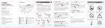
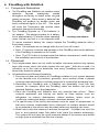
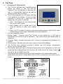
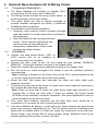
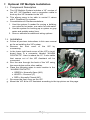
Installation and User’s Manual GF1082 V1.8 www.PipeBurstPro.com 800-246-LEAK (5325) Congratulations on the purchase of your new PipeBurst Pro Automatic Water Protection System! Please visit www.PipeBurstPro.com for new components, features, tips and tricks and troubleshooting information. Table of Contents Installation .......................................................................................................................3 1. 2. Tool Requirements ...................................................................................................3 Instructions ...............................................................................................................3 Setup and Operation .....................................................................................................4 3. Valve Interface Panel (VIP).......................................................................................4 3.1. Component Description ..............................................................................................4 3.2. Button Function ..........................................................................................................5 3.3. System Condition .......................................................................................................6 3.4. Security System Interface ...........................................................................................6 4. FloodBug with SideKick...........................................................................................8 4.1. Component Description ..............................................................................................8 4.2. Placement...................................................................................................................8 4.3. Setup .......................................................................................................................9 5. FloTrax.....................................................................................................................11 5.1. Component Description ............................................................................................11 5.2. Mounting ...................................................................................................................12 5.3. Syncing the FloTrax ..................................................................................................12 5.4. Monitor Mode ............................................................................................................12 5.5. TickerValve Operation ..............................................................................................13 5.6. Program Mode ..........................................................................................................13 5.7. Programming the FloTrax .........................................................................................14 6. Optional Base Hardwire Kit & Wiring Center .......................................................17 6.1. Component Description ............................................................................................17 6.2. Installation ................................................................................................................17 7. VIP Multiple Installation .........................................................................................18 7.1. Component Description ............................................................................................18 7.2. Installation ................................................................................................................18 8. Cleaning and Maintenance ....................................................................................19 Troubleshooting ...........................................................................................................20 1. What To Do When Water Is Detected ......................................................................20 2. Valve Interface Panel (VIP) ......................................................................................20 2|Page Installation 1. Tool Requirements Note: These tool requirements assume the TickerValve is already installed by a licensed plumber. 1.1. Electric drill, drill bits, and screwdriver tips to mount the VIP and FloTrax to your wall as desired. 1.2. Philips #1 or #2 hand screw driver for final hand tightening. 1.3. Small (1/8” wide blade) screwdriver for wire installation into the terminal blocks. 2. Instructions 2.1. EXTREMELY IMPORTANT: INSTALL TICKERVALVE AFTER ALL FIRE SUPPRESSION LINES THAT MAY BE IN PLACE FOR THE FACILITY. 2.2. Use a licensed plumber to install the 1” stainless steel TickerValve in the facilities’ inlet water line(s). Proper placement of the valve is extremely important to fully protect the facility from fire and water damage. 2.3. Position the Valve Interface Panel (VIP). a. Verify that the TickerValve wires, SideKick, and the AC adapter will reach the VIP, floor, and AC outlet Common TickerValve Installation respectively. b. For best performance keep the VIP antenna 10 inches away from metal. 2.4. Hold the VIP to the wall and mark the 2 mounting holes on wall, then attach the VIP to wall with proper mounting hardware (not included). 2.5. Remove front cover from VIP and allow it to hang via its actuator cable. 2.6. TickerValve, Freeze Relief Valve & VIP wire designation: a. Terminal 1 Motor + Red Wire b. Terminal 2 Motor - Black Wire c. Terminal 3 Open Blue Wire d. Terminal 4 Closed Green Wire e. Terminal 5 Sense White Wire 2.7. Plug battery backup into 4 pin jack inside VIP, labeled “12V BATT” and set battery inside VIP. 2.8. The FCC label is located on the inside lower surface of the VIP case, visible during the AC power and battery backup installation. 2.9. Plug in AC adapter to standard 120VAC outlet. 2.10. The basic system is now installed, and the TickerValve can be controlled by pressing on the keypad. 3|Page 2.11. Wireless FloodBug and FloTrax are now ready to be synced to the system as required. See FloodBug and FloTrax Sync instructions (Sections 3.2.a.1, 4.3.b, & 5.7.g). VIP Connections Setup and Operation 3. Valve Interface Panel (VIP) 3.1. Component Description a. The VIP is the central control and user interface for the PipeBurst Pro system. It includes basic operational instructions, 5 buttons, 5 LED’s located directly above the buttons, a temperature sensor, and an audible alarm. b. The buttons require a 2 to 7 second hold to initiate the given action and are designated by the Up Arrow ▲, Down Arrow ▼, Water Droplet , Left Arrow ◄, and Right Arrow ► (See Section 3.2). c. The LED’s, also designated by the button symbols (▲▼ ◄ ►), and the audible Valve Interface Panel alarm alert the user to the system condition through a series of beeps and lights that are either green, blinking green, red, blinking red, blinking alternately between red and green, or off (See Section 3.3). d. The temperature sensor works to provide protection from leaks created when pipes freeze and crack. Note: The Freeze Relief Valve is required for this option to be active. e. Each synced wireless device will wake up 4 times a day to report its battery condition to the VIP. 4|Page f. VIP operating modes: 1. Leak Active Mode (LAM): Entered when the VIP is first powered up and is considered the normal mode of operation for the VIP with the TickerValve. If water is detected by the FloodBug or SideKick the VIP and TickerValve will respond by immediately signaling an alarm and turning the water off to protect the facility. 2. Leak Monitor Mode (LMM): Entered manually and does not provide active water ON-OFF control; it simply informs the user of an alarmed FloodBug and action will have to be taken to turn the water off. This is normally used as the “PB256 Notifier” system without the TickerValve. 3. Sync Mode: Entered manually and is used to sync the FloodBug and FloTrax to the system (See Section 3.2.a.1 and 5.7.g). 3.2. Button Function a. ▲SYNC / LOST SYNC 1. ENTER SYNC MODE: Press ▲ for 2 seconds to enter sync mode. The VIP will beep 5 times. Release the button and the ▲ LED will begin to blink red until a device is synced or the 5 minute timeout is reached. Repeat this operation for each wireless device. 2. CLEAR ALL SYNCED DEVICES WARNING Press ▲for 5 seconds and the VIP will sound a long solid beep to signal the “CLEAR ALL SYNCED DEVICES” is near. If the button is held down longer all synced devices will be cleared from the VIP memory. 3. CLEAR ALL SYNCED DEVICES Press ▲for 7 seconds, all 5 VIP LED’s will turn red and all of the synced wireless devices are cleared from the VIP memory. NOTE: THIS ACTION CANNOT BE UNDONE! b. ▼FREEZE RELIEF VALVE / TEST 1. CYCLE FREEZE RELIEF VALVE & TICKERVALVE: Press ▼ for 7 seconds to manually initiate a test cycle of both the Freeze Relief Valve and TickerValve. c. WATER ON / OFF 1. WATER ON/OFF: Press for 2 seconds to manually open and close the TickerValve. 2. When “WATER DETECTED” alarm sounds Press for 1 second to acknowledge and mute the alarm. Repair the leak. Dry FloodBugs and SideKicks. Press again for 1 second to reset the system and open the TickerValve. If a FloodBug or SideKick is not dry the system will open the valve briefly then detect the water and immediately close the valve again. d. ◄ LEAK MONITOR MODE/ SEALED LEAD ACID BATTERY / SYNC 1. ENTER LEAK MONITOR MODE: Press ◄ for 7 seconds to enter Leak Monitor Mode. 2. EXIT LEAK MONITOR MODE: Press ► for 7 seconds performs system check and returns to Leak Active Mode. 5|Page e. ► CRITICAL SERVICE INDICATOR / RESET 1. CLEAR FAULT/MASTER RESET: Press ► for 7 seconds to attempt to clear a system fault, or perform a master reset of the system. This action will not remove the synced devices from the VIP memory. (See Section 2.1). Note: Troubleshoot and repair all faulted conditions immediately! 3.3. System Condition a. ▲SYNC / LOST SYNC 1. LED GREEN: The system is in Leak Active Mode, functioning, and all wireless devices are online. 2. LED BLINKING GREEN: There are no wireless devices synced. 3. LED BLINKING RED: A wireless device has gone offline due to a loss of power, or the VIP is in SYNC MODE and is waiting for a signal from a FloodBug or FloTrax. 4. LED BLINKING GREEN/RED: Briefly displayed to confirm a synced wireless device. After beep the VIP returns to the last assigned mode of operation either LAM or LMM. b. ▼FREEZE RELIEF VALVE / TEST 1. LED GREEN: Freeze Relief Valve Closed (Optional feature; the normal operating position). 2. LED BLINKING RED: Freeze Relief Valve Open (Optional feature; the line pressure relief position). 3. LED OFF: System operating in Leak Monitor Mode (See Section 3.1.f.2) 4. LED OFF: Freeze Relief Valve not detected in the system. c. WATER ON / OFF 1. LED GREEN: TickerValve Open, Water ON. 2. LED RED: TickerValve Closed, Water OFF. 3. LED BLINKING GREEN/RED: TickerValve not detected in the system. 4. LED OFF: System operating in Leak Monitor Mode (See Section 3.1.f.2) d. ◄ LEAK MONITOR MODE/ SEALED LEAD ACID BATTERY / SYNC 1. LED GREEN: System operating in Leak Active Mode (See Section 3.1.f.1). 2. LED BLINKING GREEN: System operating in Leak Monitor Mode (See Section 3.1.f.2). 3. LED BLINKING RED: Check Sealed Lead Acid Battery. 4. LED BLINKING GREEN/RED: No AC power. e. ► CRITICAL SERVICE INDICATOR / RESET 1. LED GREEN: System OK. 2. LED BLINKING RED: System Fault (See Section 2.1). 3.4. Security System Interface a. On the back of the VIP front panel circuit board there is a terminal block labeled ALARM CONTACTS and another labeled REMOTE SWITCH / ALARM INPUT. 1. ALARM CONTACTS – This relay switches when an alarm condition occurs allowing your security system to alert your monitoring service. Normally Open – NO Common – C Normally Closed – NC 6|Page 2. REMOTE SWITCH / ALARM INPUT Short To Close Main Valve (TickerValve) – This feature allows the security system to close the TickerValve when the alarm is set as the user exits the facility. 3. These contacts are rated for 1A 24VDC or 1A 120VAC resistive loads. 4. Thread the wires from the alarm panel through the lower rear openings of the VIP box and connect to the ALARM CONTACTS terminal block as required. 5. Consult the security system installation instructions, and/or the company that installed the system to best integrate the PipeBurst Pro with security systems. 7|Page 4. FloodBug with SideKick 4.1. Component Description a. The FloodBug and SideKick are wireless water detection devices strategically placed throughout the facility to detect water via gold plated sense pins. When water is detected the FloodBug will produce an audible alarm and send a wireless signal to the VIP. This signal will close the TickerValve and provide water protection throughout the facility. b. The FloodBug operates on 2 AA batteries or AC adapter. The design provides for a battery life of approximately 12 months when operating FloodBug with SideKick under normal use and in a non-alarmed state. To insure maximum battery life, always replace the FloodBug batteries after a flood alarm occurs. Note: The batteries do not charge while the unit is on AC power. Note: To prevent corrosion and damage to the FloodBug remove the batteries if the FloodBug is operated on AC power. Note: The FCC Label is located inside the battery compartment, visible during the installation and removal of the batteries. 4.2. Placement a. Truly irreplaceable items are not really insurable; insurance policies may replace them with money, which will never capture the real value. With this in mind, it is ultimately up to the users to determine how many FloodBugs are needed and where they should be placed. b. Considerations and Recommendations 1. The exact number and location of FloodBugs installed in your system depends on the desired level of protection, generally, more sensors create a greater coverage area and leads to a quicker response to a potentially damaging leak. 2. Remember the FloodBug with a SideKick can potentially cover two leak sources, for example; place the FloodBug under the kitchen sink and the attached SideKick under the dishwasher. 3. Place the FloodBug and SideKick near any potential leak source. Some common appliances and fixtures are known as likely leakers, such as: refrigerator ice makers, dishwashers, clothes washers, toilets, sinks, air conditioner condensate drains, showers, and water heaters, etc... 4. If a specific area of the facility has extreme costs for repair or replacement, or that area contains irreplaceable items, placement of multiple sensors should be considered in this area to stop the water before any damage can occur. 5. Water must reach the sensors to activate the system. Consider how level the floor is, and potential water flow paths; then place the sensors accordingly. The system will not have the quick response desired if the sensors are placed on high spots or shielded from the flow of water. 8|Page 6. At a minimum, you should have one FloodBug and SideKick on each level of the facility. 7. FloodBug and SideKick water detection devices are not recommended for use in steam rooms and saunas. 4.3. Setup a. Initial Power Up 1. When the FloodBug is first powered up and not yet synced to the VIP, it will chirp and then enter the water sensing mode. In this state the FloodBug will wait for an alarm interrupt signal caused by water between the gold sense pins on either the FloodBug or an attached SideKick which will produce an audible alarm. Note: The FloodBug must be synced to the VIP which is attached to a TickerValve for the system to automatically turn off the water and protect the facility. 2. The battery strength may be tested by pressing the red button on the underside of the FloodBug. It will chirp three times if its AA batteries are near full strength, twice if at fair strength, and once if the batteries are weak and need replacing. Regular battery checks are suggested to keep the PipeBurst Pro system in optimum operating condition and fully protecting the facility. If the FloodBug is synced to the system a “sync confirmation” chirp will follow the battery test chirp. b. Syncing the FloodBug 1. First, place the VIP into Sync Mode. Enter Sync Mode through the VIP (See Section 3.2.a.1) or the FloTrax (See Section 5.7.g). To fully utilize the system capabilities syncing each FloodBug through the FloTrax is highly recommended. 2. Second, press the red button on the underside of the FloodBug. The FloodBug will first give the “battery test” chirp and when communication between the FloodBug and VIP has been established it will give a rapid succession of chirps followed by three long beeps. The button may have to be pressed several times before the sync with the VIP is confirmed. 3. Repeat steps 1 and 2 to sync more FloodBugs. 4. The sync to the system can be confirmed at any time by pressing the red button and listening for the rapid succession of chirps followed by three long beeps. If the “battery test” chirp is the only one heard the FloodBug is NOT synced. 5. To remove a FloodBug from the system all wireless devices must be cleared (See Section 3.2.a.3) and the wireless devices remaining in the system must be re-synced. c. Normal Operation 1. After the FloodBug has been synced to the VIP it enters normal operation mode and is ready to begin protecting the facility. In normal operation mode each FloodBug and attached SideKick will wait for an alarm interrupt signal caused by water between the gold sense pins. If water is detected the FloodBug will produce an audible alarm and send a signal to the VIP which will immediately turn off the water by closing the TickerValve. 9|Page 2. If water is detected the system will enter a Water Detected mode and close the TickerValve. The system will remain in this state until each FloodBug and SideKick are dry and the VIP has been reset. If a FloodBug or SideKick is still wet and the system is reset the TickerValve will open then immediately reenter Water Detected mode. Note: See Troubleshooting Section 1 to manage the system when a leak has been detected. 10 | P a g e 5. FloTrax 5.1. Component Description a. The FloTrax wireless user interface panel allows the owner to tap into the full PipeBurst Pro functionality by opening the door to customizable features as well as remote control and monitoring. b. The FloTrax operates on AC power and has 2 AA batteries as backup. It may be wall mounted or placed on a table top, and always has the option of mobility. Note: The batteries do not charge while the unit is on AC power. Note: Battery life is limited and to be FloTrax used for backup or short term mobile use. Note: The FCC label is located on the inside back surface of the FloTrax case, visible during the AC power and battery backup installation. c. FloTrax operating modes: 1. Monitor Mode: Entered when the FloTrax is first synced to a VIP and is considered the normal mode of operation. The current time and system state is displayed. 2. Program Mode: Entered manually and is used to customize the PipeBurst Pro system. 3. Locate Mode: Entered manually and is used to find lost FloodBugs. d. The FloTrax user interface includes 5 buttons, an LCD screen, temperature sensor, and an audible alarm. e. The buttons allow the user to navigate through the menus displayed on the LCD f. screen and are designated by the Up Arrow ▲, Down Arrow ▼, Water Droplet , Left Arrow ◄, and Right Arrow ►. The temperature sensor works to provide protection from leaks created when pipes freeze and crack, Freeze Relief Valve (FRV) is required for this option to be active. FloTrax Menu 11 | P a g e 5.2. Mounting a. The FloTrax is designed to be wall mounted or used on a table top with its stainless steel stand. b. If convenient, use the included AC adapter for your power. Route wire through mounting holes as desired. 1. Note: If operating on AC power the blue LCD back light will remain on. c. For portable use, insert 2-AA batteries on back of unit as marked. 1. Note: Battery life is limited. d. Wall Mounting 1. Remove wall mount plate to reveal the battery slots and AC adapter jack. 2. Determine the location to mount the FloTrax. A wall stud or other solid suitable backer support is suggested. If these are not available use proper wall anchors. Mounting hardware is not included. e. Table Top 1. Press the included stainless steel stand into mating holes on the back of the wall mount plate. 5.3. Syncing the FloTrax a. Sync Mode is the initial state for a FloTrax that has not been synced to a VIP. The FloTrax will blink “FLOTRAX OFFLINE” in the upper right hand corner of the LCD to indicate that it is not yet synced to a VIP. b. Press ► or wait 60 seconds to display “PRESS SYNC” in the lower left hand corner of the LCD. The FloTrax is now ready to begin the sync process. c. Place the VIP in SYNC MODE (See Section 3.2). d. Press on the FloTrax to start sending the sync signal to the VIP. The FloTrax will beep until the VIP has received the sync signal. After the signal has been received the FloTrax will beep three times, display the time and system status, and then enter the normal Monitor Mode. e. For most effective system set up, first sync the FloTrax to the VIP then use the FloTrax to sync the FloodBugs. There are several advantages to following this procedure. 1. First, the FloTrax allows the owner the option of identifying each FloodBug with a unique location code that will help to locate where water is detected in the event of a leak. 2. Second, it allows for the installer to be mobile while setting up the system because they will not have to return to the VIP each time a new FloodBug is synced. 3. Third, by syncing the FloodBug from its operating location it is quickly confirmed that there is communication between the VIP and FloodBug and the facility will be protected. 5.4. Monitor Mode a. Monitor Mode is the normal operating mode and will display the following: 1. The current time will be displayed; this can be set through Program Mode. 2. WARNING WATER DETECTED / FREEZE DETECTED – Displayed if either or both are detected. 3. SYSTEM OK / SYSTEM FAULT – When one of the following system components is in an alarm condition and needs attention: VIP, FloodBug or SideKick. 12 | P a g e 4. FLOODBUG LOCATION / FLOODBUG SERIAL NUMBER – Displayed when water is detected, to help locate the leak. The “FloodBug Location” is displayed if it was entered via the FloTrax otherwise it will display “000000”. 5. WATER ON / WATER OFF – One or the other displayed to show the current state of the TickerValve. 6. FLOODBUG OFFLINE – Displayed when the FloodBug has lost power or is otherwise malfunctioning. 7. FLOTRAX OFFLINE – Displayed when the FloTrax has lost power or is otherwise malfunctioning. 8. REPLACE S.L.A.B. – Displayed when the Sealed Lead Acid Battery is no longer functioning properly and needs replaced. 9. FLOTRAX BATTERY LOW – Displayed when the 2 AA FloTrax batteries need replaced. 5.5. TickerValve Operation a. WATER ON is displayed in the bottom center of the LCD indicating that the TickerValve is open and the water is on. 1. To turn the water off, press and hold , the FloTrax will beep and the clock will begin to scroll the delay times. Each of the 6 optional delay times, from 0-4 hours and one custom setting, will be displayed for approximately 2 seconds, release the button when the desired delay time is displayed. 2. Delay times can be set to close the TickerValve after you leave the house for the time selected. The display will blink the selected delay time as well as the time remaining before the valve closes. This valuable feature will allow the user to let washing machines or other appliances finish their cycles before turning off the water. This is for absolute flood security if desired. 3. Delay time options: 00:00 – Instant water off 01:00 – Until water off 02:00 – Until water off 03:00 – Until water off 04:00 – Until water off Custom time, set up to 11 hours and 59 minutes, (See Section 5.3). b. WATER OFF is displayed in the bottom center of the LCD indicating that the TickerValve is closed and the water is off. 1. To turn the water on, press for 2 seconds the FloTrax will beep and WATER ON will blink. Release the button and WATER ON will continue to blink until the valve is completely open. WATER OFF disappears from the display and WATER ON is displayed. 5.6. Program Mode a. To enter Program Mode press the ▲and ▼together on the FloTrax for 3 seconds. The FloTrax will beep three times and display the program menu: 1. AUTO CYCLE SET – Sets the time of day the TV (TickerValve) and optional FRV (Freeze Relief Valve) test cycle. Generally the best setting will be in the middle of the night when it is unlikely that a 5 second pause in water flow will be an inconvenience. The default time is set at 2:00 am. 13 | P a g e 2. POWER FAIL DISABLE – When engaged the water will remain on if the AC power is lost. This is the default setting. 3. POWER FAILURE SET DELAY – The user may set a delay time (up to 11 hours 59 minutes) before the TickerValve closes turning the water off. This feature takes effect if the AC power is lost and the POWER FAILURE WATER OFF feature is engaged. 4. POWER FAILURE WATER OFF – When engaged the water will turn off if the AC power is lost. Note: The SLAB must be functioning properly for this to take effect. 5. SET DELAY TIME – The user may set a delay time (up to 11 hours 59 minutes) before the TickerValve closes turning the water off. This feature takes effect when the TickerValve is manually operated via the button (See Section 5.4.a.9). 6. SPRINKLER DELAY – Turns the water on and back off for a set time each day after the user has manually turned the water off via the button (See Section 3.2, & 5.4.a.9). This allows the user the option of turning the water off during away times and making water available for sprinkler systems, cleaning and maintenance staff, or any other required water use. Note: This setting has no effect if the water has turned off due to an alarm signal. 7. SYNC FLOODBUG – Places the VIP in Sync Mode from a remote location. It is then possible to sync a wireless device from this same location and type in the custom location code. To fully utilize the system capabilities syncing the FloodBugs through the FloTrax is highly recommended. 8. TIME SET – The user may set the current local time. The time is set to Central Standard Time when shipped from the factory. b. Press ▲or ▼to scroll through the various programmable options, the active selection is indicated by blinking text. c. Press ►to enable the currently blinking program mode to be selected. d. After a program mode has been enabled, press ►for 2 seconds to exit back to the program menu. e. Press ◄ while in Program Mode returns the FloTrax to Monitor Mode. f. If no option is selected for 30 minutes the FloTrax will reset to Monitor Mode, saving all settings. 5.7. Programming the FloTrax a. AUTO CYCLE SET 1. Press ◄ or ►to move through the hour, minute, and AM / PM fields. 2. Press ▲or ▼to increment the hour, minute, and AM / PM fields up and down. 3. Press ◄ for 2 seconds the FloTrax will beep once and exit without updating the delay time. 4. Press ►for 2 seconds the FloTrax will beep three times, exit and save the new time. b. POWER FAIL DISABLE 1. “WATER ON” is displayed on the LCD indicating that when the AC power is lost the water will remain on. This is the default state. 14 | P a g e 2. If “WATER ON” is not displayed then the POWER FAILURE WATER OFF feature has been engaged and the water will turn off when the AC power is lost. 3. Press ►for 2 seconds to engage the POWER FAIL DISABLE feature and “WATER ON” will be displayed. 4. To disable this feature the POWER FAILURE WATER OFF feature must be engaged. c. POWER FAILURE SET DELAY 1. Press ◄ or ►to move through the hour and minute fields. 2. Press ▲or ▼to increment the hour and minute fields up and down. 3. Press ◄ for 2 seconds the FloTrax will beep once and exit without updating the delay time. 4. Press ►for 2 seconds the FloTrax will beep three times, exit and save the new time. d. POWER FAILURE WATER OFF 1. “WATER OFF” is displayed on the LCD indicating the POWER FAILURE WATER OFF feature has been engaged and the water will turn off when the AC power is lost. 2. If the LCD is blank in the “WATER ON / WATER OFF” location the water will remain on when the AC power is lost the water will remain on. This is the default state. 3. Pressing ►for 2 seconds will engage the POWER FAILURE WATER OFF feature, beep three times and “WATER OFF” will be displayed. 4. To disable this feature the POWER FAIL DISABLE feature must be engaged. e. SET DELAY TIME 1. Press ◄ or ►to move through the hour and minute fields. 2. Press ▲or ▼to increment the hour and minute fields up and down. 3. Press ◄ for 2 seconds the FloTrax will beep once and exit without updating the delay time. 4. Press ►for 2 seconds the FloTrax will beep three times, exit and save the new time. f. SPRINKLER DELAY 1. SPRINKLER START is initially blinking, press ▲or ▼to allow the user to toggle between SPRINKLER START/STOP. 2. After the start or stop is selected press ►to set the time. 3. Press ◄ or ►to move through the hour, minute, and AM / PM fields. 4. Press ▲or ▼to increment the hour, minute, and AM / PM fields up and down. 5. Press ◄ for 2 seconds the FloTrax will beep once and return to SPRINKLER START/STOP without updating the time. 6. Press ►for 2 seconds will the FloTrax beep three times, save the new time, and return to SPRINKLER START/STOP. 7. Press ▲or ▼to select the other set point, either start or stop, and set the desired time as described above. 8. Press ◄ to exit back to the program menu. g. SYNC FLOODBUG 1. The FloTrax will beep twice and PRESS SYNC will blink on the LCD screen. 15 | P a g e 2. Press the red sync button underneath the FloodBug. Button may need to be pressed several times to complete the sync (See Section 4.3). 3. After the FloodBug has been synced, the FloTrax displays the last 4 digits of the FloodBug serial number and a programmable location code of AAA000 where the first character is blinking. Subsequent syncing operations will display the last location code entered. 4. Press ◄ or ►to move through the location code fields. 5. Press ▲or ▼to scroll through the location code digits (first three characters A-Z and 0-9, last three characters 0-9) and type in the custom code. 6. Document the serial number and location code entered before moving forward, this will be the only record of the customized location codes. 7. Press ◄ for 2 seconds the FloTrax will exit without updating the location code, and will display 000000 as the location code if that device goes into alarm. 8. Press ►for 2 seconds the FloTrax will exit and save the new location code. Codes may be duplicated, as the wireless devices are identified by serial number. h. TIME SET 1. Press ◄ or ►to move through the hour, minute, and AM / PM fields. 2. Press ▲or ▼to increment the hour, minute, and AM / PM fields up and down. 3. Press ◄ for 2 seconds the FloTrax will beep once and exit without updating the delay time. 4. Press ►for 2 seconds the FloTrax will beep three times, exit and save the new time. 16 | P a g e 6. Optional Base Hardwire Kit & Wiring Center 6.1. Component Description a. The Base Hardwire Kit includes an Adapter Wire, Junction Box, 5 Wall Jacks, and 5 SideKicks. b. The Wiring Center includes the wiring center device, 4 mounting screws, and location labels. c. This option allows the user to expand coverage to multiple locations throughout the facility, if additional FloodBugs were not desired. d. Considerations and Recommendations 1. Generally, more sensors create a greater coverage area and leads to a quicker response to a potentially damaging leak. 2. Place the SideKick near any potential leak source. Some common appliances and fixtures known as likely leakers are: refrigerators, dishwashers, toilets, sinks, showers, and water heaters. Wiring Center & Junction Box 6.2. Installation a. Caution: use solid strand Phone, CAT3, or CAT5 control wire for all hardwire kit Base Hardwire Kit connection points (not included). b. Remove the back cover of the VIP and locate the jack labeled “SIDEKICK SENSOR”. Unplug the SideKick and plug in the Adapter Wire. c. Mount the Junction Box securely as desired and plug in the Adapter Wire. d. Run the home run cable throughout the facility to gain the greatest protective coverage area. Note: Installing a SideKick in the same room as the VIP is recommended as this is usually a key potential leak area of the entire facility. e. Mount the Wall Jack plates and terminate the home run cable under each respective terminal. f. Terminate the other end of the home run cable wires under respective terminals in the Junction Box and fasten securely. Note: Place no more than 5 home run cable wires under each terminal in the Junction Box. If there are more than 5 home run cables, the Wiring Center (GF9030) will be needed to complete installation. See www.PipeBurstPro.com for more information on the Wiring Center. g. Fully insert each SideKick connector into the Wall Jack; there should be no movement in or out when the wire is pulled and pushed. h. Test each SideKick by placing a small amount of water between the gold sensor pads, once system is completely set up. The VIP should close the TickerValve and signal with an audible alarm, if it does not; check the connections at the wall jack, Wiring Center, and Junction Box to ensure proper wiring. SideKicks must be dry before resetting of the system, or else it will fault. 17 | P a g e 7. Optional VIP Multiple Installation 7.1. Component Description a. The VIP Multiple System includes a “W” version of the VIP, VIP Assistant, and a connection cable to hook up the VIP Assistant to the VIP. b. This allows users to be able to control 2 valves with 1 PipeBurst Pro system. c. Considerations & Recommendations 1. Use this system if needed for zoning a building, one valve for hot water, one valve for cold water. 2. Use this system for hooking up a system on gray water and potable water lines. 3. See our website for additional wiring options. 7.2. Installation a. Follow all previous instructions in this user manual VIP Multiple as far as installing the VIP system. b. Remove the front cover of the VIP by unscrewing. c. In the lower right hand corner of the VIP’s circuit board there is a connector labeled “ALARM CONTACTS”. Here is where the 15” 3 wire cable that comes out of the VIP Assistant will be connected. d. Run the wire through the back of the VIP using the same holes as the other cables. e. Place the following wires in each location in the “ALARM CONTACTS”. GREEN = Normally Open (NO) WHITE = Common (C) RED = Normally Closed (NC) Correct Wiring Order VIP f. Re-screw the front cover on the VIP. g. Mount the VIP & the VIP Assistant according to the top picture on this page. 18 | P a g e 8. Cleaning and Maintenance 8.1. Annual system cleaning and check is recommended to ensure proper operation. Cleaning the FloodBugs & SideKicks with a wet towel accomplishes many tasks at once. a. The cleaning keeps the gold sense pads free of any dirt, debris, or other material that may inhibit the detection of water. b. The operation of the TickerValve and the alarm is checked when the wet sponge bridges across the gold sensor pins. If the valve does not close and/or the alarm does not sound contact your service representative. c. After the TickerValve has closed from the alarm open the valve by pressing . By operating the TickerValve it will help keep clear of hard water mineral build up on interior valve components and free to operate when needed. If the valve does not open or close when is pressed contact your service representative. 19 | P a g e Troubleshooting 1. What To Do When Water Is Detected 1.1. When the FloodBug and / or SideKick detect water: a. The TickerValve will close b. The FloodBug, VIP, and FloTrax will sound an alarm c. Press on the VIP to mute the VIP alarm 1. Note: The FloTrax will continue to sound the alarm until the system has been reset or the FloTrax power is removed. d. The LED on the VIP will blink red e. The FloTrax will display “Warning Water Detected”, “Water Off”, “FloodBug Location”, and “FloodBug Ser. No.” 1. Note: The FloTrax will not display a location or serial number if the SideKick attached to the VIP is the water detection point. 1.2. Locate and dry each FloodBug and SideKick that has detected water and remove them from the water path 1.3. Locate the source of the leak and repair 1.4. Press to open the TickerValve and return to normal operation 2. Valve Interface Panel (VIP) 2.1. System Fault a. System Faults Include: 1. Over current situation has occurred on the TickerValve or Freeze Relief Valve motor 2. Under current (zero current) has occurred on the TickerValve motor 3. No TickerValve in the system 4. No control signal on detected on the TickerValve 20 | P a g e Customer Support: GreenField Direct, LLC 14015 238th Street Greenwood, NE 68366 http://www.greenfielddirect.com/contact.php Fax: (402) 944-2402 Phone: (800) 246-LEAK (800-246-5325) E-Mail: [email protected] Operating Hours: Monday - Friday, 9:00am - 4:00pmCST (Excludes Major Holidays) Warranty - PipeBurst Pro Products 7 Year Limited Warranty th GreenField Direct, LLC of 14015 238 St, Greenwood, NE 68366 (“Warrantor”), warrants to the original purchaser and installed location of the PipeBurst Pro, manufactured by Warrantor, and to any person to whom such originally installed equipment is transferred to via the transfer of said real property that original installation was made, that such equipment shall be free from defects in materials and workmanship during a two (2) year period; additionally the electric valve actuator enclosure and its’ electronic components inside, shall be free from interior moisture damage for a period of seven (7) years; both periods commencing upon the receipt of order date for such equipment from the original purchaser thereof; (the “warranty periods”). Note: Full warranty details can be found at: http://www.pipeburstpro.com/pdf/Warranty.pdf FCC Compliance Statement: This device complies with part 15 of the FCC Rules. Operation is subject to the following two conditions: (1) This device may not cause harmful interference, and (2) this device must accept any interference received, including interference that may cause undesired operation. Changes or modifications not expressly approved by the party responsible for compliance could void the user's authority to operate the equipment. Power Requirements: For Indoor Use Only Requirements for US & Canada Use supplied AC Adapter VIP Input Output 100-240V ~50/60Hz 1.0A MAX 18V DC 2.22A FloodBug / FloTrax Input Output 100-240V ~50/60Hz 0.2A MAX 5V DC 1.2A 21 | P a g e Notes: 22 | P a g e Maintenance Record: 23 | P a g e www.PipeBurstPro.com 800-246-LEAK (5325) 24 | P a g e

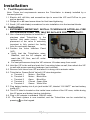


![20120815_PipeBurst Pro Jr User Manual V1[...]](http://vs1.manualzilla.com/store/data/005915031_1-fc76e6520fc4c8a26c3a91dcf3e505a9-150x150.png)