1
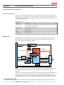
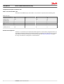
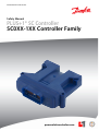
MAKING MODERN LIVING POSSIBLE
Safety Manual
PLUS+1® SC Controller
SC0XX-1XX Controller Family
powersolutions.danfoss.com
Safety Manual
PLUS+1 SC0XX-1XX Controller Family
Revision history
Table of revisions
2
Date
Changed
Rev
December 2014
First edition
AA
L1420375 • Rev AA • December 2014
Safety Manual
PLUS+1 SC0XX-1XX Controller Family
Contents
Introduction
This safety manual............................................................................................................................................................................4
Certified SIL 2 Capable.............................................................................................................................................................. 4
Reference manuals..................................................................................................................................................................... 4
Model-specific API and data sheets......................................................................................................................................4
Latest version of technical literature....................................................................................................................................5
PLUS+1® SC Controller support................................................................................................................................................... 5
Component description and failure rates
Processors and subsystems.......................................................................................................................................................... 6
FMEDA analysis................................................................................................................................................................................. 6
Failure categories description......................................................................................................................................................7
PLUS+1® SC Controller failure rates............................................................................................................................................8
Recommended diagnostics.......................................................................................................................................................... 8
Design considerations
Safety critical function.................................................................................................................................................................... 9
Recommended diagnostics.....................................................................................................................................................9
User application software development requirements............................................................................................. 10
User application software development requirements (continued).....................................................................11
Environmental limits.....................................................................................................................................................................11
Application limits........................................................................................................................................................................... 11
Design verification.........................................................................................................................................................................11
SIL capability....................................................................................................................................................................................12
Systematic capability...............................................................................................................................................................12
Random capability................................................................................................................................................................... 12
Connection of the PLUS+1® SC Controller to sensors and actuators ......................................................................... 12
Requirements.................................................................................................................................................................................. 12
Installation and operation considerations
Installation........................................................................................................................................................................................ 13
Physical location and placement ............................................................................................................................................ 13
Repair and replacement ............................................................................................................................................................. 13
Useful life...........................................................................................................................................................................................13
Software/hardware version numbers.....................................................................................................................................13
Security considerations................................................................................................................................................................13
Danfoss Power Solutions notification ................................................................................................................................... 13
Using the FMEDA results
PFH calculation or PFDAVG calculation PLUS+1® SC Controller .....................................................................................14
Example application, failure rate analysis........................................................................................................................14
Abbreviations and definitions
Abbreviations.................................................................................................................................................................................. 15
Definitions........................................................................................................................................................................................ 15
L1420375 • Rev AA • December 2014
3
Safety Manual
PLUS+1 SC0XX-1XX Controller Family
Introduction
This safety manual
This safety manual provides information necessary to design, implement, verify and maintain a safety
critical function utilizing the PLUS+1® SC Controller. This manual provides necessary requirements for
meeting the IEC 61508 functional safety standard.
W
Warning
Read manual completely before programming your application.
Certified SIL 2 Capable
The SC0XX-1XX Controller Family is certified SIL 2 Capable when deployed with the certified SIL 2
Capable OS that is embedded in their respective SC0XX-1XX HWD files.
The SC0XX-0XX Controller Family is designed for meeting the needs of SIL 2 applications where the OEM
certifies at the machine level. The SC0XX-0XX Controller Family is not certified SIL 2 Capable as a
component regardless of the HWD files with which it is deployed. The table below summarizes this
information (the HWD filenames are representative, but not actual).
In all cases, the OEM/customer is responsible for the safety integrity requirement, implementation, and
validation of their application.
Controller
Family
HWD for the Primary
Processor
HWD for the Secondary
Processor
Component-Level
SIL 2 Capable
Machine-Level
SIL 2 Capable
SC0XX-1XX
SC0XX-1XX_HWD_Primary*
SC0XX-1XX_HWD_Secondary* Yes
SC0XX-1XX
SC0XX-0XX_HWD_Primary
SC0XX-0XX_HWD_Secondary
No
Yes
SC0XX-0XX
SC0XX-1XX_HWD_Primary*
SC0XX-1XX_HWD_Secondary* No
Yes
SC0XX-0XX
SC0XX-0XX_HWD_Primary
SC0XX-0XX_HWD_Secondary
Yes
Yes
No
* These HWD files incorporate the certified SIL 2 Capable OS with Safety Diagnostic Functions.
Reference manuals
Manual
Title
Type
Identification number
PLUS+1® SC0XX-1XX Controller Family
Technical Information
L1415500
PLUS+1® GUIDE Software User Manual
Operation Manual
10100824
How to Install PLUS+1® GUIDE Upgrades
Operation Manual
11078040
Model-specific API and data sheets
API and data sheet
SC Controller model
4
Literature identification number
Primary processor HW
description—API
Secondary processor HW
description—API
Data Sheet
SC050-120/122
70156324
70156321
L1410421
SC024-120/122
70156499
70156500
L1410171
SC024-110/112
70156496
70156498
L1410890
SC050-13H
70153891
70153903
L1407546
L1420375 • Rev AA • December 2014
Safety Manual
PLUS+1 SC0XX-1XX Controller Family
Introduction
Latest version of technical literature
Danfoss product literature is online at: http://powersolutions.danfoss.com/literature/
PLUS+1® SC Controller support
Contact information is online at: http://powersolutions.danfoss.com/products/PLUS-1-GUIDE/PLUS-1support-and-training/
L1420375 • Rev AA • December 2014
5
Safety Manual
PLUS+1 SC0XX-1XX Controller Family
Component description and failure rates
Processors and subsystems
The PLUS+1® SC Controller contains two processors, the primary and the secondary processor, which
communicate asynchronously with each other. The PLUS+1® SC Controller has six main subsystems, each
of which was analyzed individually. The configuration of a specific controller deployment is a function of
the user application software.
Analyzed subsystems
Subsystem
Description
Common Logic
Electrical components and circuitry typically involved with all applications regardless of the
input-output channel configuration
DIN/AIN/FreqIN
Digital analog and frequency input pins
CrntIn (current)
Current input pins
ResIN
Resistance input pins
DOUT
Digital output pins
CrntOUT (current)
Current output pins
FMEDA analysis
The FMEDA analysis results include the elements shown in the following diagram (components and
inputs/outputs are color coded, blue for the primary processor and red for the secondary processor).
PLUS+1 SC Controller—Parts included in the FMEDA
Connector
Power input
VLDP
Protection and power supplies
Power return
Comparator check
V ref
14 V 3 V 5 V
CAN1
PWM shut-off [1:8]
Secondary
processor
3V
(supply and reference)
Clock 2
Inputs [1:24]
Input
conditioning
CAN1
Shut-off check [1:14]
Voltage
supervisor 2
3V
Clock 1
DOUT shut-off [1:6]
Reset
Async COM
Voltage
supervisor 1
Primary
processor
CAN2
Outputs
Power return
DOUT status feedback [1:6]
DOUT control [1:6]
Sensor power
PWM outputs [1:8]
PWM current feedback [1:8]
PWM control [1:8]
External
memory
DOUT [1:6]
The PLUS+1® SC Controller is classified as a Type B1 high demand mode component in accordance to IEC
61508. The hardware fault tolerance is a function of the system architecture which will vary by
application.
The PLUS+1® SC Controller is certified to provide a 1oo1D architecture in accordance with IEC 61508. This
allows the conclusion that a CAT2 architecture, in accordance with ISO 13849 or ISO 25119 can be
implemented. For example this can be accomplished by using the primary processor as main controller
for the Safety Function and the secondary processor as diagnostic element (intelligent watch dog, TE1
6
Type B component: “Complex” element (using microcontrollers or programmable logic); for details see 7.4.4.1.3 of IEC 61508.
L1420375 • Rev AA • December 2014
Safety Manual
PLUS+1 SC0XX-1XX Controller Family
Component description and failure rates
Test Equipment) to observe the correct function of the primary processor and to de-energize (safe-state)
independently all corresponding safety-related outputs.
Detailed analysis, review and documentation for compliance to ISO 13849 or ISO 25119 has to be done by
the designer or integrator of the safety related system.
Failure categories description
In order to judge the failure behavior of the PLUS+1® SC Controller, the following definitions for the
failure of the component apply.
Definitions for failure of the component
Failure category(1)
Definition
Fail-Safe State
State where the safety output is de-energized.
Fail Safe
State where the safety output is de-energized.
Fail Detected
Failure that is detected by the PLUS+1® SC Controller and causes the
output signal to go to the predefined fail safe state.
Fail Dangerous
Failure that deviates the measured input state or the actual output by
more than the safety accuracy (2% of span) and that leaves the output
within the active range.
Fail Dangerous Undetected
Failure that is dangerous and that is not being diagnosed by automatic
diagnostics or expected user logic.
Fail Dangerous Detected
Failure that is dangerous but is detected by automatic diagnostics or is
expected to be detected by user logic.
Fail High(2)(3)
Failure that causes a safety input signal to go to a value that is clearly
above the normal range and can therefore be reliably detected by the
user application software.
Fail Low(2)(3)
Failure that causes a safety input signal to go to a value that is clearly
below the normal range and can therefore be reliably detected by the
user application software.
No Effect
Failure of a component that is part of the safety function but that has no
effect on the safety function.
Annunciation Detected
Failure that does not directly impact safety but does impact the ability to
detect a future fault (such as a fault in a diagnostic circuit) and that is
detected by internal diagnostics.
Annunciation Undetected
Failure that does not directly impact safety but does impact the ability to
detect a future fault (such as a fault in a diagnostic circuit) that is not
detected by internal diagnostics.
λSD
Failure rate of all safe detected failures
λSU
Failure rate of all safe undetected failures
λDD
Failure rate of all dangerous detected failures
λDU
Failure rate of all dangerous undetected failures
λD
Failure rate of all dangerous failures, detected and undetected
AD
Failure rate of all annunciation detected failures
AU
Failure rate of all annunciation undetected failures
FIT
Failure In Time (1x10⁻⁹ failures per hour)
(1) The failure categories listed above, expand upon the categories listed in IEC 61508, which are only safe and
dangerous, both detected and undetected. In IEC 61508, the No Effect failures cannot contribute to the failure rate
of the safety function. Therefore, they are not used for the Safe Failure Fraction calculation.
(2) Depending on the application, a Fail High or a Fail Low failure can either be safe or dangerous and may be
detected or undetected depending on the user software application program.
(3) Consequently, during a Safety Integrity Level (SIL) verification assessment, the Fail High and Fail Low failure
categories need to be classified as safe or dangerous, and as detected or undetected.
L1420375 • Rev AA • December 2014
7
Safety Manual
PLUS+1 SC0XX-1XX Controller Family
Component description and failure rates
PLUS+1® SC Controller failure rates
The results of the FMEDA analysis for the PLUS+1® SC Controller are presented in the following table.
Failure rates (FIT)
Controller Subsystem
λSD
λSU
λDD
λDU
Common Logic
2451
16
2556
263
DIN/AIN/FreqIN
0
11
0
22
CrntIn (current)
0
5
0
5
ResIN
0
11
0
11
DOUT
73
38
28
1
CrntOUT (current)
143
1
36
10
Recommended diagnostics
The PLUS+1® SC Controller can be implemented with diagnostics to detect many dangerous failures and
other failures that would result in the controller operating in a degraded mode. The machine integrator is
responsible for the safety and compliance to relevant standards. See Safety critical function on page 9
for design considerations and diagnostics recommendations.
8
L1420375 • Rev AA • December 2014
Safety Manual
PLUS+1 SC0XX-1XX Controller Family
Design considerations
Safety critical function
The PLUS+1® SC Controller can perform a wide variety of control functions. If these control functions of
the primary processor are safety critical, then additional safety reliability can be achieved by configuring
the secondary processor to monitor the sensor inputs, perform diagnostics, and act to bring the machine
to a safe state if safe operating parameters are violated. The recommended configuration is to use the
secondary processor to monitor the control function of the primary processor.
Recommended diagnostics
The following table lists recommended diagnostics. These diagnostics are implemented in the user
application software that would be loaded into the PLUS+1® SC Controller.
W
Warning
If these diagnostics are not implemented, then all dangerous failures should be treated as dangerous
undetected failures.
Diagnostics
Function
Failure mode
Condition
Action
Continuous or Start-up
Sensor power
Short to battery
Analog reading at or near
maximum
Stop reading inputs
powered by sensor power.
Continuous
Sensor power
Short to ground
Analog reading at or near
zero
Stop reading inputs
powered by sensor power.
Continuous
Sensor power
Out of range
Analog reading different
than expected
Can compensate inputs for
new voltage if possible
Continuous
Analog input
At Max
Analog reading at or near
max
Stop using this input
Continuous
Analog input
At zero volts
Analog reading at or near
zero
Stop using this input
Continuous
Current driver
Load shorted
Duty cycle at least 50% less
than expected for known
load
Information only or turn off
output
Continuous
Current driver
Load shorted
Status signal indicates short
circuit
Turn off output immediately Continuous
Current driver
Open load
Duty cycle at least 50% less
than expected for known
load
Information only or turn off
output
Start-up
Current driver
Incorrect load
Coil resistance is greatly
different than expected
Do not use that output
Continuous
Digital input
Load shorted
Status signal indicates short
circuit or open load
Application dependent
Continuous
Digital input
Open load
Status signal indicates short
circuit or open load
Application dependent
Continuous
Battery Power
Dangerously High
Battery voltage reading
above 36V
Turn off all outputs and
ignore inputs
Continuous
Battery Power
Dangerously Low
Battery voltage reading
below 7V
Turn off all PWM outputs
Continuous
Frequency input
Open
Analog reading is at or near
middle voltage
Ignore frequency input
Continuous
Frequency input
No signal
Analog value doesn't change Ignore frequency input
for longer than the
maximum period
Continuous
L1420375 • Rev AA • December 2014
9
Safety Manual
PLUS+1 SC0XX-1XX Controller Family
Design considerations
Diagnostics (continued)
Function
Failure mode
Condition
Action
Continuous or Start-up
CAN
Bus off
CAN bus status signal
indicates bus off
Turn off outputs that rely on
CAN information
Continuous
CAN
Time out
An expected message hasn't Turn off outputs that rely on
been received in the
that message
expected time
Continuous
CAN
Failed transition
Application requests
message transmission while
pending flag is active
Continuous
Configuration
Invalid configuration
Status signal indicates input Make change to application
or output is configured in an software
invalid way.
Application dependent
Start-up
User application software development requirements
W
Warning
The application programmer must apply these software development requirements when developing
their safety-related system to insure the most robust safety integrity of the system architecture.
•
•
•
•
•
•
•
•
•
•
•
•
•
•
•
•
•
10
CAN bus must not be used for safety critical functions, unless CAN-BE-SAFE protocol/product from
Danfoss is deployed.
All changes made to the configuration through the service tool must be verified by the user to ensure
that they function as expected in the safety controller.
The system must be designed with de-energized as the safe state.
Appropriate action must be taken to put the system into a safe state when an output to outputfeedback mismatch error is identified by the application.
The user application software must include plausibility checks on frequency input data to detect
possible failures in frequency input calculations.
EEPROM data must include software part number and the user application software should check
that this matches with the application.
The user application software must include plausibility checks on all safety relevant inputs.
If data is shared between the primary and secondary processors through the internal UART, time
monitoring must be used to ensure that messages are being sent within the expected time period.
The user application software must take appropriate action to put the system into a safe state when a
current feedback reading mismatch is reported.
If the user application allows it, the current output must periodically be set to zero to allow the zero
offset to be recalculated.
For optimal performance, the output current should be set to zero after large temperature changes (>
25° C (77° F)) to allow the zero offset to be re-calculated
If the checksum on the EEPROM fails, the user application software must shutdown outputs (deenergize) depending on the EEPROM data or use default data if that can be done safely.
Redundant channels must be utilized to provide reliability where there is concern about channel
reliability based on PFH.
Signal comparisons must be implemented by the user application software to compare signals
between primary and secondary processors for safety related signals. Function blocks from the Safety
Library can help with this task.
Wiring of the control must be done in compliance with the Danfoss wiring guidelines addressed in
PLUS+1® SC0XX-1XX Controller Family Technical Information, L1415500.
The user application software must implement strategies to mitigate against the effects of corrupted
RAM. For example, include shadow copies of safety critical data and checksums of data.
Internal UART communication implemented by user application software must have as a minimum
control mechanism of a heartbeat with sequence signal.
L1420375 • Rev AA • December 2014
Safety Manual
PLUS+1 SC0XX-1XX Controller Family
Design considerations
User application software development requirements (continued)
W
Warning
The application programmer must apply these software development requirements when developing
their safety-related system to insure the most robust safety integrity of the system architecture.
•
•
•
•
In all cases, the sensor power supply must be monitored and taken into a ratiometric calculation for
the analog inputs.
The user application software must implement shutdown of safety critical outputs either by the
primary or the secondary processor or by both processors based on user application software safety
requirements.
The user application software must be tested for proper function including fault insertion testing. For
more details, see the topic Software Safety Validation and the chapter Risk Reduction in the PLUS+1®
GUIDE User Manual, 10100824.
The user application software must be tested for proper response to:
‒ Highest frequency input conditions.
‒ Highest frequency output conditions.
‒ Highest CAN traffic load conditions on the corresponding used CAN buses.
•
•
•
•
•
•
The user application software must verify that the OSExecTimeout can meet the process safety time.
The OS.ChecksumFailureTreatment parameter allows the user application software to override
memory corruption faults and to continue operation instead of turning off all outputs. The user
application software must not override faults, since doing so could result in an unsafe condition.
The user application software must verify that either the primary or the secondary processors or both
processors are capable of disabling the safety related outputs.
The user application software must use the frequency values and the count value of the Quad
encoder inputs to validate functionality.
The user application software must verify that the current output overload status returns to zero after
commanding zero current output.
A Functional Safety Assessment must be conducted before designing any safety related system using
the PLUS+1® SC Controller.
Environmental limits
The designer or integrator of a safety critical function must verify that the safety controller is rated for use
within the expected environmental limits of the target application. Refer to Model-specific API and data
sheets on page 4 for the model-specific PLUS+1® SC Controller Data Sheet, for environmental limits.
Application limits
The designer or integrator of a safety critical function must check that the safety controller is rated for use
within the expected application limits. Refer to the PLUS+1® SC0XX-1XX Controller Technical Information,
L1415500, for safety controller limits.
Design verification
Refer to PLUS+1 SC Controller failure rates on page 8 for a summary of failure rates for the PLUS+1® SC
Controller.
The achieved Safety Integrity Level (SIL) of an entire Safety Critical Function design must be verified by
the designer or integrator via a calculation of PFH considering the I/O required, demand mode, any
implemented diagnostics, safety time, and architecture.
The failure rate data listed the FMEDA report is only valid for the useful lifetime of a PLUS+1® SC
Controller. The failure rates will increase sometime after this useful lifetime period. Reliability calculations
based on the data listed in the FMEDA report for mission times beyond the lifetime may yield results that
are too optimistic, in other words, the calculated Safety Integrity Level will not be achieved.
L1420375 • Rev AA • December 2014
11
Safety Manual
PLUS+1 SC0XX-1XX Controller Family
Design considerations
SIL capability
Systematic capability
The systematic capability of the PLUS+1® SC0XX-1XX Controller Family is SC 2 per IEC 61508.
Random capability
Refer to PLUS+1 SC Controller failure rates on page 8 for a summary of failure rates for the PLUS+1® SC
Controller.
For each user application, the failure rates for the particular configuration should be determined and
compared to the allowable failure rate for a given SIL target.
Connection of the PLUS+1® SC Controller to sensors and actuators
The connection of the PLUS+1® SC Controller to the required sensors and actuators must be performed in
accordance with the PLUS+1® SC0XX-1XX Controller Family Technical Information, L1415500.
Requirements
•
•
•
•
•
The system’s response time must be less than the process safety time defined by the user application.
The worst-case response time for a change of value of an analog input or contact signal (measured at
the terminals) through the complete system to the completion of change of state of the analog
output or contact output (measured at the terminals) will be a maximum of 10 ms plus the user
application software programmed ExecTimeOut, as measured to the standard outputs. This worst
case time must be determined for the worst-case loading of the safety controller. See Model-specific
API and data sheets on page 4.
The diagnostic self-checks other than the RAM diagnostic self-test and CRC on Flash application must
be performed based on demand every loop time, the delay time from the onset of a failure to the
time at which the outputs reach the safe state will be a maximum of 10 ms plus the user application
software program parameter, ExecTimeOut.
The time interval of RAM diagnostic self-check for the platform is a maximum of 1 hour. The time
interval RAM test is reported to the user application software.
The CRC flash check time for the user application software is a maximum of 1 hour and is reported to
the user application software.
Diagnostics and response times
•
•
•
•
•
12
Description
Worst case time Additional information
Diagnostics and Response Times
1 hour
Depends on total size of RAM
Flash CRC error detect from onset to 1 hour
safe state
Depends on total size of Flash memory
Change of input to output
10 ms
Not including ExecTimeOut
Diagnostic error detection time
from onset to safe state
10 ms
Diagnostics are based on demand during execution
loop
The maximum delay time from the onset of a failure to the time at which the outputs reach the safe
state is the diagnostic time interval plus 10 ms.
All safety related system components, including the PLUS+1® SC Controller, must be operational
before machine operation.
Personnel must verify that the PLUS+1® SC Controller is suitable for use in safety applications by
confirming the PLUS+1® SC Controller’s nameplate is properly marked.
Personnel performing testing on the PLUS+1® SC Controller must be competent to perform such
testing. Functional Safety Training is provided by Danfoss Power Solutions, and details can be found
on the Danfoss Power Solutions website at: http://powersolutions.danfoss.com/solutions/Functionalsafety/.
Results from the functional tests and diagnostics must be recorded and reviewed periodically.
L1420375 • Rev AA • December 2014
Safety Manual
PLUS+1 SC0XX-1XX Controller Family
Installation and operation considerations
Installation
The PLUS+1® SC Controller must be installed per standard practices outlined in the PLUS+1® SC0XX-1XX
Controller Family Technical Information, L1415500. The environment must be checked to verify that
environmental conditions do not exceed the ratings. Instructions on installation of latest version of the
safety controller HWD file are found in How to Install PLUS+1® GUIDE Upgrades Operation Manual,
11078040.
Physical location and placement
The PLUS+1® SC Controller must be mounted in accordance with the PLUS+1® SC0XX-1XX Controller Family
Technical Information, L1415500, in a low vibration environment. If excessive vibration is expected,
special precautions must be taken to ensure the integrity of electrical connections or the vibration should
be reduced using appropriate damping mounts.
Repair and replacement
The PLUS+1® SC Controllers are not repairable and no maintenance of them is required.
Useful life
The useful life of the PLUS+1® SC Controller is 30 years. No proof tests are required.
Software/hardware version numbers
See the Application Interface Document for the relevant PLUS+1® SC Controller, Model-specific API and
data sheets on page 4.
Security considerations
The PLUS+1® SC Controller does not use data that the user can configure externally, for example, by the
PLUS+1 Service Tool. The user application software may contain data that is configured externally. If this
is the case, then suitable security should be provided. The PLUS+1® GUIDE Software User Manual,
10100824 provides a description of how to handle parameters in a safe way.
Danfoss Power Solutions notification
Any failures that are detected and that compromise functional safety should be immediately reported to
Danfoss Power Solutions. Any change suggestions for future improvements or new features can be
forwarded to Danfoss Power Solutions:
Contact information is online at: http://powersolutions.danfoss.com/products/PLUS-1-GUIDE/PLUS-1support-and-training/
L1420375 • Rev AA • December 2014
13
Safety Manual
PLUS+1 SC0XX-1XX Controller Family
Using the FMEDA results
PFH calculation or PFDAVG calculation PLUS+1® SC Controller
An average Probability of Failure per Hour (PFH) or an average Probability of Failure on Demand (PFDAVG),
depending on the operating mode, must be determined for each Safety Critical Function. The total will
include the failure rate of all sensors and actuators that are required to perform the function as well as the
elements of the PLUS+1® SC Controller that are utilized.
Since the elements of the controller subsystem vary based on the Safety Critical Function implemented,
the contribution for the PLUS+1® SC Controller needs to be determined for each application.
To demonstrate how to calculate the contribution of the PLUS+1® SC Controller, consider the example of
a steering function that is safety critical. The steering function relies on a Steer Command that is
transmitted by a joystick utilizing a single ResIN – Resistance Mode Input. The controller processes the
input and controls the movement of the machine through a dual path control subsystem utilizing four
CrntOUT outputs.
This safety critical function would have an overall failure rate that is the sum of controller subsystems
used which are:
• (1) Common Logic
• (1) ResIN
• (4) CrntOUT (current)
In a machine application, the safety critical function could be operating in high demand. In a high
demand function, only the dangerous undetected failures are included when calculating the PFH. To be
considered a high demand application, the diagnostics must be executed 10 times faster than the
process safety time. Care must be taken when modeling a function as high demand. It is recommended
that the designer or integrator review the requirements with Danfoss Power Solutions to help avoid
understating PFH.
Example application, failure rate analysis
The following table is for an example application. Consider for this example, the function is a high
demand system.
Failure rate analysis for the example function
Controller Subsystem
Quantity
λSD
λSU
λDD
λDU
Total λD
Common Logic
1
2451
16
2556
263
2819
DIN/AIN/FreqIN
0
0
11
0
22
22
CrntIn (current)
0
0
5
0
5
5
ResIN
1
0
11
0
11
11
DOUT
0
73
38
28
1
29
CrntOUT (current)
4
143
1
36
10
46
3023
31
2700
314
3014
Example Total (Sum of
Quantity multiplied by
Column Value)
The implementation of the recommended diagnostics (Section 3.1) affects the system failure rate. For
example, if all recommended diagnostics are implemented, only the undetected failures (λDU) contribute
to the failure rate, which is 314 FITS or 3.14x10⁻⁷ failures per hour. This results in a SFF of 94.8%, which is a
SIL2 compliant system.
If none of the recommended diagnostics are implemented, then all failures (λSD, λDU, λDD) are treated as
undetected failures. In this example, the failure rate would then be 3014 FITs or 3.014x10⁻⁶ failures per
hour, which does not meet the SIL2 requirement, but does meet the SIL1 requirements.
14
L1420375 • Rev AA • December 2014
Safety Manual
PLUS+1 SC0XX-1XX Controller Family
Abbreviations and definitions
Abbreviations
Abbreviations
Abbreviation
Definition
EUC
Equipment under control.
FMEDA
Failure modes, effects and diagnostic analysis.
HFT
Hardware fault tolerance.
PFH
Probability of failure per hour.
PFDAVG
Average probability of failure on demand.
SFF
Safe failure fraction, summarizes the fraction of failures which lead to a safe state and
the fraction of failures which will be detected by diagnostic measures and lead to a
defined safety action.
SIF
Safety instrumented function.
SIL
Safety integrity level.
SRS
Safety related system, implementation of one or more safety critical functions. An SRS
is composed of any combination of sensor(s), control module(s), and actuator(s).
DIN/AIN/FreqIN
Digital analog and frequency input pins.
CrntIn (current)
Current input pins.
ResIN
Resistance input pins.
DOUT
Digital output pins.
CrntOUT (current)
Current output pins.
OS
Operating system.
Definitions
Definitions
Term
Definition
Continuous Demand Mode
Mode where the safety function retains the equipment under control in a safe state as
part of its normal operation.
High Demand Mode
Mode where the safety function is only performed on demand, in order to transfer the
EUC into a specified safe state, and where the frequency of demands is greater than
one per year.
Low Demand Mode
Mode where the safety function is only performed on demand, in order to transfer the
EUC into a specified safe state, and where the frequency of demands is not greater
than one per year. NOTE: The E/E/PE safety-related system that performs the safety
function normally has no influence on the EUC or EUC control system until a demand
arises. However, if the E/E/PE safety-related system fails in such a way that it is unable
to carry out the safety function, then it may cause the EUC to move to a safe state (see
7.4.6 of IEC 61508).
Safety
Freedom from unacceptable risk of harm.
Functional Safety
The ability of a system to carry out the actions necessary to achieve or to maintain a
defined safe state for the equipment, machinery, plant, and apparatus under control of
the system.
Basic Safety
The equipment must be designed and manufactured such that it protects against risk
of damage to persons by electrical shock and other hazards and against resulting fire
and explosion. The protection must be effective under all conditions of the nominal
operation and under single fault conditions.
Safety Assessment
The investigation to arrive at a judgment, based on evidence of the safety achieved by
safety-related systems.
Safety Critical Function
A set of equipment intended to reduce the risk due to a specific hazard.
L1420375 • Rev AA • December 2014
15
Safety Manual
PLUS+1 SC0XX-1XX Controller Family
Abbreviations and definitions
Definitions (continued)
16
Term
Definition
Process Safety Time
The period of time between a failure occurring in the control system (with the potential
to give rise to a hazardous event) and the occurrence of the hazardous event if the
safety function is not performed.
Type A Component
Non-Complex element (using discrete elements); for details see 7.4.4.1.2 of IEC 61508.
Type B Component
Complex element (using micro controllers or programmable logic); for details see
7.4.4.1.3 of IEC 61508.
Common Logic
Electrical components and circuitry typically involved with all applications regardless of
the input-output channel configuration.
L1420375 • Rev AA • December 2014
Safety Manual
PLUS+1 SC0XX-1XX Controller Family
L1420375 • Rev AA • December 2014
17
Safety Manual
PLUS+1 SC0XX-1XX Controller Family
18
L1420375 • Rev AA • December 2014
Safety Manual
PLUS+1 SC0XX-1XX Controller Family
L1420375 • Rev AA • December 2014
19
Products we offer:
•
•
•
•
•
•
•
•
•
•
•
•
•
•
•
•
Bent Axis Motors
Closed Circuit Axial Piston
Pumps and Motors
Displays
Electrohydraulic Power
Steering
Electrohydraulics
Danfoss Power Solutions is a global manufacturer and supplier of high-quality hydraulic and
electronic components. We specialize in providing state-of-the-art technology and solutions
that excel in the harsh operating conditions of the mobile off-highway market. Building on
our extensive applications expertise, we work closely with our customers to ensure
exceptional performance for a broad range of off-highway vehicles.
We help OEMs around the world speed up system development, reduce costs and bring
vehicles to market faster.
Danfoss – Your Strongest Partner in Mobile Hydraulics.
Hydraulic Power Steering
Go to www.powersolutions.danfoss.com for further product information.
Integrated Systems
Wherever off-highway vehicles are at work, so is Danfoss. We offer expert worldwide support
for our customers, ensuring the best possible solutions for outstanding performance. And
with an extensive network of Global Service Partners, we also provide comprehensive global
service for all of our components.
Joysticks and Control
Handles
Microcontrollers and
Software
Open Circuit Axial Piston
Pumps
Orbital Motors
Please contact the Danfoss Power Solution representative nearest you.
PLUS+1® GUIDE
Proportional Valves
Sensors
Steering
Transit Mixer Drives
Comatrol
www.comatrol.com
Schwarzmüller-Inverter
www.schwarzmuellerinverter.com
Local address:
Turolla
www.turollaocg.com
Valmova
www.valmova.com
Hydro-Gear
www.hydro-gear.com
Daikin-Sauer-Danfoss
www.daikin-sauer-danfoss.com
Danfoss
Power Solutions (US) Company
2800 East 13th Street
Ames, IA 50010, USA
Phone: +1 515 239 6000
Danfoss
Power Solutions GmbH & Co. OHG
Krokamp 35
D-24539 Neumünster, Germany
Phone: +49 4321 871 0
Danfoss
Power Solutions ApS
Nordborgvej 81
DK-6430 Nordborg, Denmark
Phone: +45 7488 2222
Danfoss
Power Solutions
(Shanghai) Co., Ltd.
Building #22, No. 1000 Jin Hai Rd
Jin Qiao, Pudong New District
Shanghai, China 201206
Phone: +86 21 3418 5200
Danfoss can accept no responsibility for possible errors in catalogues, brochures and other printed material. Danfoss reserves the right to alter its products without notice. This also applies to
products already on order provided that such alterations can be made without changes being necessary in specifications already agreed.
All trademarks in this material are property of the respective companies. Danfoss and the Danfoss logotype are trademarks of Danfoss A/S. All rights reserved.
L1420375 • Rev AA • December 2014
www.danfoss.com
© Danfoss A/S, 2014