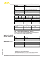
1
Safety Manual
VEGATOR 111, 112
With SIL qualification
Document ID: 49220
Contents
Contents
1 Document language
2Scope
2.1 Instrument version............................................................................................................. 4
2.2 Area of application............................................................................................................ 4
2.3 SIL conformity................................................................................................................... 4
3Planning
3.1 Safety function.................................................................................................................. 5
3.2 Safe state.......................................................................................................................... 5
3.3 Prerequisites for operation................................................................................................ 5
4 Safety-related characteristics
4.1 Characteristics in accordance with IEC 61508 for level detection...................................... 6
4.2 Characteristics in accordance with IEC 61508 for range monitoring.................................. 6
4.3 Figures according to ISO 13849-1..................................................................................... 7
4.4 Supplementary information............................................................................................... 8
5Setup
5.1 General information........................................................................................................... 9
5.2 Adjustment instructions..................................................................................................... 9
6 Diagnostics and service
6.1 Behaviour in case of failure............................................................................................. 10
6.2Repair............................................................................................................................. 10
7 Proof test
7.1 General information......................................................................................................... 11
7.2 Test 1 - without input current simulation........................................................................... 11
7.3 Test 2 - with input current simulation................................................................................ 11
7.4 Test 3 - with switch-on pulse checking............................................................................. 12
8 Appendix A - Test report
9 Appendix B - Term definitions
10 Supplement C - SIL conformity
2
VEGATOR 111, 112 • With SIL qualification
49220-EN-141002
Editing status: 2014-09-26
1 Document language
1 Document language
Das vorliegende Safety Manual für Funktionale Sicherheit ist verfügbar in den Sprachen
Deutsch, Englisch, Französisch und Russisch.
EN
The current Safety Manual for Functional Safety is available in German, English, French and
Russian language.
FR
Le présent Safety Manual de sécurité fonctionnelle est disponible dans les langues suivantes:
allemand, anglais, français et russe.
RU
Данное руководство по функциональной безопасности Safety Manual имеется на
немецком, английском, французском и русском языках.
49220-EN-141002
DE
VEGATOR 111, 112 • With SIL qualification
3
2 Scope
2Scope
2.1 Instrument version
This safety manual applies to signal conditioning instruments
VEGATOR 111, 112
Input signal:
•
NAMUR (IEC 60947-5-6)
•
from HW Ver 1.0.0
•
•
Version VEGATOR 111: fail safe relay
Version VEGATOR 112: two-point control mode
Valid version:
The following functions are excluded from safety-relevant applications:
2.2 Area of application
The signal conditioning instruments can be used with a suitable transducer for level detection or range monitoring in a safety-instrumented
system in accordance with IEC 61508 in the low demand mode or
high demand mode:
•
•
Up to SIL2 in a single-channel architecture
Up to SIL3 in a multiple-channel architecture
•
•
Version VEGATOR 111: relay 1
Version VEGATOR 121: relay 1 or relay 2
The following interface should be used to output the measured value:
In a SIL3 architecture the two channels may not be used redundantly
in the VEGATOR 112!
2.3 SIL conformity
The SIL conformity was independently judged and certified by the
TÜV Rheinland according to IEC 61508:2010 (Ed.2).1)
The certificate is valid for the entire service life of all instruments that
were sold before the certificate expired!
4
Verification documents see appendix
VEGATOR 111, 112 • With SIL qualification
49220-EN-141002
1)
3 Planning
3Planning
Level detection with VEGATOR 111 or 112
3.1 Safety function
The transducer fed by the signal conditioning instrument generates a
signal of > 1.6 mA or < 1.6 mA corresponding to the process variable.
A level detection relay is switched dependent on this signal and on
the selected mode.
This applies for both channels in the VEGATOR 112 version if the twopoint control is not selected.
Mode monitoring with
VEGATOR 112
Two transducers fed by the signal conditioning instrument each
generates a signal of > 1.6 mA or < 1.6 mA corresponding to the process variable. Two limit values can therefore be measured for range
monitoring.
The following points must be observed here:
•
•
•
•
Safe state
The two NO contacts must be connected in series
Channel for the upper limit: Max. mode
Channel for the lower limit: Min. mode
The two-point control may not be selected
3.2 Safe state
The safe condition of the output is independent of the mode, by definition the currentless state of the relay (quiescent current principle).
Therefore only the NO contact may be used for safety-relevant applications.
Output signals in case of
malfunction
Instructions and restrictions
Relay outputs:
•
3.3 Prerequisites for operation
• The measuring system should suit the application. The application•
•
•
•
•
49220-EN-141002
NO contacts open
specific limits must be maintained
The specifications according to the operating instructions manual,
particularly the current load on the output circuits, must be kept
within the specified limits
To avoid a fusing of the relay contacts, these must be protected by
an external fuse that triggers at 60 % of the max.contact current
load.
The installation site must comply with IP 54 protection
The instructions in chapter "Safety-related characteristics", paragraph "Supplementary information" must be noted
All parts of the measuring chain must correspond to the planned
"Safety Integrity Level (SIL)"
VEGATOR 111, 112 • With SIL qualification
5
4 Safety-related characteristics
4 Safety-related characteristics
VEGATOR 111 or one
channel of the VEGATOR
112
4.1 Characteristics in accordance with IEC 61508
for level detection
Parameter
Value
Safety Integrity Level
SIL2 in single-channel architecture
Hardware error tolerance
HFT = 0
Instrument type
Type A
Mode
Low demand mode, High demand mode
SIL3 in multiple channel architecture2)
SFF
MTBF
> 60 %
1.93 x 10⁶ h (220 years)
3)
Fault reaction time
< 2 s
4)
Failure rates
λS
170 FIT
λDD
29 FIT
λDU
46 FIT
λH
0 FIT
λL
0 FIT
λAD
0 FIT
PFDAVG
0.038 x 10⁻²
(T1 = 1 year)
PFDAVG
0.057 x 10⁻²
(T1 = 2 years)
PFDAVG
0.111 x 10⁻²
(T1 = 5 years)
PFH
0.046 x 10⁻⁶ 1/h
λAU
19 FIT
Coverage with the proof test (PTC)
Remaining dangerous
undetected failures
PTC
Test 1
5 FIT
89 %
Test 2 and 3
2 FIT
96 %
Test type5)
VEGATOR 112
4.2 Characteristics in accordance with IEC 61508
for range monitoring
Parameter
Value
Safety Integrity Level
SIL2 in single-channel architecture
SIL3 in multiple channel architecture6)
3)
6
VEGATOR 111, 112 • With SIL qualification
49220-EN-141002
Homogeneous redundancy possible (see note in the section "Area of Applicaton").
Including errors outside the safety function.
4)
Time between the occurrence of the event and the output of a fault signal.
5)
See section "Proof test".
6)
Homogeneous redundancy possible.
2)
4 Safety-related characteristics
Parameter
Value
Hardware error tolerance
HFT = 0
Instrument type
Type A
Mode
Low demand mode, High demand mode
SFF
> 60 %
MTBF7)
1.65 x 10⁶ h (188 years)
Fault reaction time8)
< 2 s
Failure rates
λS
240 FIT
λDD
44 FIT
λDU
74 FIT
λH
0 FIT
λL
0 FIT
λAD
0 FIT
PFDAVG
0.062 x 10⁻²
(T1 = 1 year)
0.091 x 10⁻²
(T1 = 2 years)
PFDAVG
0.178 x 10
(T1 = 5 years)
PFDAVG
PFH
-2
λAU
35 FIT
0.074 x 10⁻⁶ 1/h
Coverage with the proof test (PTC)
Remaining dangerous
undetected failures
PTC
Test 1
8 FIT
89 %
Test 2 and 3
2 FIT
97 %
Test type9)
4.3 Figures according to ISO 13849-1
Level detection with VEGATOR 111 or one channel of the VEGATOR 112
49220-EN-141002
Range monitoring with
VEGATOR 112
Derived from the safety-related characteristics, the following figures
result according to ISO 13849-1 (machine safety):10)
Parameter
Value
MTTFd
1522 years
DC
38 %
Performance Level
4.61 x 10⁻⁸ 1/h (corresponds to "e")
Parameter
Value
MTTFd
970 years
DC
37 %
Performance Level
7.38 x 10⁻⁸ 1/h (corresponds to "e")
Including errors outside the safety function.
Time between the occurrence of the event and the output of a fault signal.
See section "Proof test".
10)
ISO 13849-1 was not part of the certification of the instrument.
7)
8)
9)
VEGATOR 111, 112 • With SIL qualification
7
4 Safety-related characteristics
Determination of the
failure rates
4.4 Supplementary information
The failure rates of the instrument were determined by an FMEDA
according to IEC 61508. Basis for the calculations are the component
failure rates according to SN 29500.
All figures refer to an average ambient temperature of 40 °C (104 °F)
during the operating time. For higher temperatures, the values should
be corrected:
•
•
Assumptions of the
FMEDA
Similar factors apply if frequent temperature fluctations are expected.
• The failure rates are constant. Take note of the useful service life of
•
•
•
•
•
Calculation of PFDAVG
the components according to IEC 61508-2.
Multiple errors are not taken into account
Wear on mechanical parts is not taken into account
Failure rates of external power supplies are not taken into account
The environmental conditions correspond to an average industrial
environment
To avoid a fusing of the relay contacts, these must be protected by
an external fuse
The values for PFDAVG specified above were calculated as follows for a
1oo1 architecture:
(1 – PTC) × λ DU × LT
PTC × λ DU × T1
PFDAVG =
+ λ DD x MTTR +
2
2
•
•
•
•
Multiple channel architecture
Continuous application temperature > 50 °C (122 °F) by factor 1.3
Continuous application temperature > 60 °C (140 °F) by factor 2.5
T1 (Proof Test Interval)
MTTR = 8 h
PTC = 90 %
LT = 10 years
In multiple channel systems for SIL3 applications, this measuring system can also be used in a homogeneously redundant configuration.
The safety-related characteristics must be calculated especially for
the selected structure of the measuring chain using the stated failure
rates. In doing this, a suitable Common Cause Factor must be considered (see IEC 61508-6, appendix D).
49220-EN-141002
8
VEGATOR 111, 112 • With SIL qualification
5 Setup
5Setup
5.1 General information
Mounting and installation Take note of the mounting and installation instructions in the operating
instructions manual.
Adjustment elements
5.2 Adjustment instructions
The operating elements must be set according to the application. The
function of the operating elements as well as the parameter adjustment procedure are described in the operating instructions.
The safety function must be considered unsafe during the setting
process! Other actions must be taken to maintain the safety function
if necessary.
With regard to the switch on/swich off delay it must be ensured that
the sum of all switching delays from the transducer to the actuator is
adapted to the process safety time!
49220-EN-141002
The instrument must be protected against inadvertent or unauthorized
operation!
VEGATOR 111, 112 • With SIL qualification
9
6 Diagnostics and service
6 Diagnostics and service
6.1 Behaviour in case of failure
Internal diagnosis
The instrument is permanently monitored by an internal diagnostic
system. If a malfunction is detected, the respective output signals
change to the status configured especially for this condition (see section "Safe status").
Error messages
The occurrence of an error is signalled by the red LED and, if necessary, by the fail safe relay.
Reaction when malfunctions occur
6.2Repair
If faults are detected, the entire measuring system must be shut down
and the process held in a safe state by other measures.
The manufacturer must be informed of the occurrence of a dangerous, undetected error (incl. fault description).
49220-EN-141002
10
VEGATOR 111, 112 • With SIL qualification
7 Proof test
7 Proof test
Objective
7.1 General information
To identify possible undetected, dangerous failures, the safety function must be checked by a proof test at adequate intervals. It is the
user's responsibility to choose the type of testing. The time intervals
are subject to the PFDAVG in chapter "Safety-related characteristics").
For documentation of these tests, the test protocol in the appendix
can be used.
If one of the tests proves negative, the entire measuring system must
be switched out of service and the process held in a safe state by
means of other measures.
Preparation
Unsafe device
status
In a multiple channel architecture this applies separately to each
channel.
•
•
Determine safety function (mode, switching points)
If necessary, remove the instruments from the safety chain and
maintain the safety function by other means
Warning:
During the function test, the safety function must be treated as unreliable. Take into account that the function test influences downstream
connected devices.
If necessary, you must take other measures to maintain the safety
function.
After the function test, the status specified for the safety function must
be restored.
Conditions
Procedure
Expected result
Coverage of the test
Conditions
49220-EN-141002
Procedure
Expected result
7.2 Test 1 - without input current simulation
•
•
Use of any transducer
Output signals correspond to the current limit level
1. Push the min./max. switch on the VEGATOR 111, 112
2. Check relay contacts
•
•
about 1: Relay and LED display change states
about 2: Relay contacts open and close according to item 1
See Safety-related characteristics
7.3 Test 2 - with input current simulation
•
•
Possibility of sensor current simulation exists
Output signals correspond to the current limit level
1. Invert sensor current by means of the min./max. switch on the
transducer (2.1 mA/1.2 mA)
2. Check relay contacts
•
•
about 1: State of relay and LED display follow the simulated sensor current
about 2: Relay contacts open and close according to item 1
VEGATOR 111, 112 • With SIL qualification
11
7 Proof test
Coverage of the test
Conditions
Procedure
Expected result
See Safety-related characteristics
7.4 Test 3 - with switch-on pulse checking
•
•
1. Press test key
2. Check relay contacts
•
•
Coverage of the test
Use of a VEGAVIB 60 or VEGAWAVE 60 transducer with NAMUR
output
Output signals correspond to the current limit level
about 1: State of relay and LED display follows the switch-on pulse
(the curve of the switch-on pulse is described in the transducer
operating instructions)
about 2: Relay contacts open and close according to item 1
See Safety-related characteristics
49220-EN-141002
12
VEGATOR 111, 112 • With SIL qualification
8 Appendix A - Test report
8 Appendix A - Test report
Identification
Company/Tester
Plant/Instrument TAG
Meas. loop TAG
Instrument type/Order code
Instrument serial number
Date, setup
Date, last function test
Test reason
Test scope
(…)
(…)
without input current simulation
(…)
with switch-on pulse checking
(…)
Setup
Proof test
(…)
Mode
Delay times
Max. Channel 1 (…); channel 2 (…)
Min.
(…)
with input current simulation
(…)
Channel 1 (…); channel 2 (…)
(…)
Range monitoring
Switch-on delay
Switch-off delay
Test result for test 1 and 2
Limit level
signal
Channel 1
Min./Max.
switch channel 1
Condition
Relay 1
Limit level
signal
Condition
Test result
Channel 2
Min./Max.
switch channel 2
Limit level
signal
State function test
Condition
Test result
Relay 2
Test result for test 3
Limit level
signal
Channel 1
State function test
Condition
Relay 1
Channel 2
Empty signal
Empty signal
Full signal
Full signal
Relay 2
49220-EN-141002
Confirmation
Date:
Signature:
VEGATOR 111, 112 • With SIL qualification
13
9 Appendix B - Term definitions
Abbreviations
9 Appendix B - Term definitions
SIL
Safety Integrity Level
HFT
Hardware Fault Tolerance
SFF
Safe Failure Fraction
PFDAVG
Average Probability of dangerous Failure on Demand
PFH
Average frequency of a dangerous failure per hour (Ed.2)
FMEDA Failure Mode, Effects and Diagnostics Analysis
FIT
Failure In Time (1 FIT = 1 failure/109 h)
λSD
Rate for safe detected failure
λS
λS = λSD + λSU
λDU
Rate for dangerous undetected failure
λL
Rate for failure, who causes a low output current (≤ 3.6 mA)
λAU
Rate for diagnostic failure (undetected)
λSU
Rate for safe undetected failure
λDD
Rate for dangerous detected failure
λH
Rate for failure, who causes a high output current (> 21 mA)
λAD
Rate for diagnostic failure (detected)
DC
Diagnostic Coverage
PTC
Proof Test Coverage
T1
Proof Test Interval
LT
Useful Life Time
MTBF
Mean Time Between Failure
MTTF
Mean Time To Failure
MTTR
Mean Time To Restoration (Ed.2)
MTTFd
Mean Time To dangerous Failure (ISO 13849-1)
PL
Performance Level (ISO 13849-1)
49220-EN-141002
14
VEGATOR 111, 112 • With SIL qualification
10 Supplement C - SIL conformity
49220-EN-141002
10 Supplement C - SIL conformity
VEGATOR 111, 112 • With SIL qualification
15
All statements concerning scope of delivery, application, practical use and operating conditions of the sensors and processing systems correspond to the information
available at the time of printing.
Subject to change without prior notice
© VEGA Grieshaber KG, Schiltach/Germany 2014
VEGA Grieshaber KG
Am Hohenstein 113
77761 Schiltach
Germany
Phone +49 7836 50-0
Fax +49 7836 50-201
E-mail: [email protected]
www.vega.com
49220-EN-141002
Printing date: