1
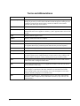
ST 3000 Smart Transmitter
Release 300 with HART® Communications Options
Safety Manual
Doc. No.:
Revision Date:
34-ST-25-31
November 2009
Notices and Trademarks
Copyright 2009 by Honeywell Inc.
November 2009
While this information is presented in good faith and believed to be accurate, Honeywell disclaims the
implied warranties of merchantability and fitness for a particular purpose and makes no express warranties
except as may be stated in its written agreement with and for its customers.
In no event is Honeywell liable to anyone for any indirect, special or consequential damages. The
information and specifications in this document are subject to change without notice.
Honeywell is a U.S. registered trademarks of Honeywell Inc.
Other brand or product names are trademarks of their respective owners.
Honeywell Process Solutions
Honeywell
512 Virginia Drive
Fort Washington, PA 19034
ii
ST 3000 Safety Manual
11/09
About This Document
Contact Info
World Wide Web
−
The following lists Honeywell’s World Wide Web sites that will be of interest to our industrial automation
and control customers.
Honeywell Organization
WWW Address (URL)
Corporate
http://www.honeywell.com
Honeywell Process Solutions
http://www.honeywell.com/ps
Telephone
Contact us by telephone at the numbers listed below.
Organization
United States and Canada
11/09
Honeywell Inc.
Phone Number
1-800-343-0228
1-800-525-7439
ST 3000 Safety Manual
Sales
Service
iii
Terms and Abbreviations
1oo1
One out of one
Basic Safety
The equipment must be designed and manufactured such that it protects against risk of
damage to persons by electrical shock and other hazards and against resulting fire and
explosion. The protection must be effective under all conditions of the nominal
operation and under single fault condition
FMEDA
Failure Modes, Effects and Diagnostic Analysis
Functional Safety
The ability of a system to carry out the actions necessary to achieve or to maintain a
defined safe state for the equipment / machinery / plant / apparatus under control of the
system
GTS
Global Technical Support Center
®
iv
HART
Highway Addressable Remote Transmitter
HFT
Hardware Fault Tolerance
Low demand mode
Mode, where the frequency of demands for operation made on a safety-related system
is no greater than one per year and no greater than twice the proof test frequency.
PFDAVG
Average Probability of Failure on Demand
Safety
Freedom from unacceptable risk of harm
Safety Assessment
The investigation to arrive at a judgment - based on evidence - of the safety achieved
by safety-related systems. Further definitions of terms used for safety techniques and
measures and the description of safety related systems are given in IEC 61508-4.
SFF
Safe Failure Fraction, the fraction of the overall failure rate of a device that results in
either a safe fault or a diagnosed unsafe fault.
SIF
Safety Instrumented Function, a set of equipment intended to reduce the risk due to a
specific hazard (a safety loop).
SIL
Safety Integrity Level, discrete level (one out of a possible four) for specifying the
safety integrity requirements of the safety functions to be allocated to the E/E/PE
safety-related systems where Safety Integrity Level 4 has the highest level of safety
integrity and Safety Integrity Level 1 has the lowest.
SIS
Safety Instrumented System – Implementation of one or more Safety Instrumented
Functions. A SIS is composed of any combination of sensor(s), logic solver(s), and
final element(s).
ST 3000 Safety Manual
11/09
Contents
Terms and Abbreviations .......................................................................................... iv
1 — Requirements ..................................................................................................... 1
Requirements for use of the manual ...................................................................................................1
2 — Safety Function................................................................................................... 1
Primary Safety Functions ....................................................................................................................1
Secondary Safety Functions ...............................................................................................................1
Systematic Integrity: SIL 3 Capable ....................................................................................................1
3 — Designing with the HONEYWELL ST 3000 ........................................................ 2
Diagnostic Response Time .................................................................................................................2
Logic Solver Inputs ..............................................................................................................................2
Reliability data and lifetime limit ..........................................................................................................2
Environmental limits ............................................................................................................................2
Application limits..................................................................................................................................2
4 — Installation with the HONEYWELL ST 3000 ....................................................... 3
Parameter settings ..............................................................................................................................3
5 — Operation and Maintenance with the HONEYWELL ST 3000 ........................... 4
Proof test .............................................................................................................................................4
Repair and replacement ......................................................................................................................5
11/09
ST 3000 Safety Manual
v
vi
ST 3000 Safety Manual
11/09
1 — Requirements
Requirements for use of the manual
This section is intended for user’s who have our ST 3000 Smart Transmitter with either the
HART® Communication option HC or HART® Communication option H6 and the SL (SIL)
option. Anything other than these option combinations is not specifically covered by this manual.
2 — Safety Function
Primary Safety Functions
The HONEYWELL ST 3000 measures the (pressure gauge, differential, absolute) of a process
and reports the measurement within a safety accuracy of 2%.
Secondary Safety Functions
The HONEYWELL ST 3000 performs automatic diagnostics to detect internal failures and
reports these failures via out of band signals on the 4 – 20 mA output.
Systematic Integrity: SIL 3 Capable
SIL 3 Capability:
The product has met manufacturer design process requirements of Safety Integrity Level (SIL) 3.
These are intended to achieve sufficient integrity against systematic errors of design by the
manufacturer. A Safety Instrumented Function (SIF) designed with this product must not be used
at a SIL level higher than the statement without “prior use” justification by end user or diverse
technology redundancy in the design.
11/09
ST 3000 Safety Manual
1
3 — Designing with the HONEYWELL ST 3000
Diagnostic Response Time
The HONEYWELL ST 3000 will report an internal failure within 15 minutes of fault occurrence
(worst case).
Logic Solver Inputs
The logic solver must be configured so that the engineering range in the transmitter matches the
expected range of the logic solver.
To take advantage of the internal diagnostics in the ST 3000, the logic solver must be configured
to annunciate an out of band current reading (greater than 20.8 mA. or less than 3.8 mA.) in
standard instrument or (greater than 21.0 mA. or less than 3.6 mA.) with Namur “NE” option as a
diagnostic fault. The logic solver configuration must consider the slew time of the current signal
and ensure that filtering is used to prevent a false diagnostic failure annunciation.
Reliability data and lifetime limit
A detailed Failure Mode, Effects, and Diagnostics Analysis (FMEDA) report is available from
HONEYWELL. This report details all failure rates and failure modes, common cause factors for
applications with redundant devices and the expected lifetime of the HONEYWELL ST 3000.
The HONEYWELL ST 3000 is intended for low demand mode applications up to SIL 2 for use
in a simplex (1oo1) configuration, depending on the PFDAVG calculation of the entire Safety
Instrumented Function.
The development process of the HONEYWELL ST 3000 is certified up to SIL3, allowing
redundant use of the transmitter up to this Safety Integrity Level, depending the PFDAVG
calculation of the entire Safety Instrumented Function.
When using the HONEYWELL ST 3000 in a redundant configuration, a common cause factor
should be included in reliability calculations. For details see the FMEDA report.
The reliability data listed the FMEDA report is only valid for the useful life time of the
HONEYWELL ST 3000. The failure rates of the HONEYWELL ST 3000 may increase
sometime after this period. Reliability calculations based on the data listed in the FMEDA report
for mission times beyond the lifetime may yield results that are too optimistic, i.e. the calculated
Safety Integrity Level will not be achieved.
Environmental limits
The environmental limits of the HONEYWELL ST 3000 are specified in the User Manual.
Application limits
The application limits of the HONEYWELL ST 3000 are specified in the User Manual. If the
transmitter is used outside of the application limits the reliability data provided becomes invalid.
2
ST 3000 Safety Manual
11/09
4 — Installation with the HONEYWELL ST 3000
No special installation is required in addition to the standard installation practices outlined in the
ST 3000 Smart Transmitter User Manual. However please note that when the device is in safety
operation the optional write protect jumper must be set so that the device is write protected and
HART® devices must be disconnected. See ST 3000 Smart Transmitter User Manual for details
concerning the write protect jumper.
Parameter settings
The following parameters need to be set in order to maintain the designed safety integrity:
mA Fault action (Upscale/Downscale)
If the standard failsafe option is specified in
the model selection number (option “NE” is
not specified) the transmitter is shipped with a
default failsafe direction of upscale (20.8
mA.). This is acceptable for all high trip
applications. For low trip applications, the failsafe direction is downscale (3.8 mA.). A
jumper on the transmitter may be changed to
accomplish this action, see the Users Manual.
If the NAMUR (NE43) failsafe option “NE” is
specified in the model selection number the
transmitter is shipped with a default failsafe
direction of upscale (21.0 mA.). This is
acceptable for all high trip applications. For
low trip applications, the fail-safe direction is
downscale (3.6 mA.). A jumper on the
transmitter may be changed to accomplish
this action, see the Users Manual.
Engineering Range
All engineering range parameters must be
entered to match the trip points in the safety
logic solver. These parameters must be
verified during the installation and
commissioning to ensure that the correct
parameters are set in the transmitter.
Engineering range parameters can be verified
by reading these parameters from the local
display or by checking actual calibration of the
transmitter.
PV Damping
The process safety time must be considered
when selecting the PV Damping Time
Constant. A damping time must be low
enough to ensure that the safety instrumented
function process safety time is achieved.
11/09
ST 3000 Safety Manual
3
5 — Operation and Maintenance with the
HONEYWELL ST 3000
Proof test
The objective of proof testing is to detect failures within the HONEYWELL ST 3000 that are not
detected by the automatic diagnostics of the transmitter. Of main concern are undetected failures
that prevent the safety instrumented function from performing its intended function.
The frequency of proof testing, or the proof test interval, is to be determined in reliability
calculations for the safety instrumented functions for which the HONEYWELL ST 3000 is
applied. The exida exSILentia® tool is recommended for these calculations. The proof tests must
be performed more frequently than, or as frequently as specified in the calculation in order to
maintain the required safety integrity of the safety instrumented function.
The following proof test is recommended. It consists of a simple HART® driven min to max
output test. The results of the proof test need to be documented and this documentation should be
part of a plant safety management system. Any failures that are detected and that compromise
functional safety should be reported to the Global Technical Support Center (GTS).
Step
Action
1
Bypass the safety PLC or take other appropriate action to avoid a false trip, following
Management of Change procedures.
2
Send a HART command to the transmitter to go to the high alarm current output and verify
that the analog current reaches that value.
®
This procedure tests for compliance voltage problems such as a low loop power supply
voltage or increased wiring resistance. This also tests for other possible failures.
3
®
Send a HART command to the transmitter to go to the low alarm current output and verify
that the analog current reaches that value.
This test checks for possible quiescent current related failures.
®
4
Use the HART communicator to view detailed critical and non-critical device status to
ensure no alarms or warnings are present in the transmitter.
5
Verify all safety critical configuration parameters.
6
Restore the loop to full operation.
7
Remove the bypass from the safety PLC or otherwise restore normal operation.
This test will detect approximately 56% of possible DU failures in the transmitter (Proof Test
Coverage). An alternative proof test consisting of proof test 1 with actual three point pressure
calibration plus verification of the temperature measurement will detect approximately 99% of
possible DU failures.
The person(s) performing the proof test of the HONEYWELL ST 3000 should be trained in SIS
operations, including bypass procedures, transmitter maintenance and company Management of
Change procedures. Tools required are: handheld communicator.
4
ST 3000 Safety Manual
11/09
Repair and replacement
Any failures that are detected and that compromise functional safety should be reported to the
Global Technical Support Center (GTS).
When replacing the HONEYWELL ST 3000 the procedures in the installation manual should be
followed.
FIRMWARE UPDATE
In case firmware updates are required they should be performed at the factory. The replacement
responsibilities are then in place. The user will not be required to perform any firmware updates.
11/09
ST 3000 Safety Manual
5
Honeywell Process Solutions
Honeywell
34-ST-25-31
512 Virginia Drive
November 2009
Fort Washington, PA 19034
©2009 Honeywell International Inc.
www.honeywell.com/ps