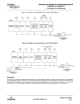
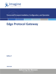
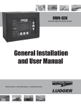
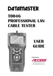
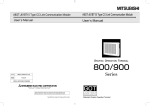
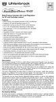
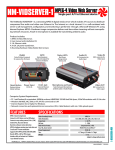
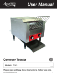
1
Connecting the NetMedia MM70 MicroModulator™ M
CABLE MAIN OR
OTHER TV SIGNAL*
M
7
0
*If you combine input from an
antenna with output from the
MM70, NetMedia strongly
suggests that you place an inline amplifier between the
SPLITTER/COMBINER antenna and the splitter/
combiner.
AUDIO
LEFT
RIGHT
MM70
OUTPUT
VIDEO
AUDIO/VIDEO SOURCES
HEAD END OF HOME
CABLE DISTRIBUTION
VCR/LASERDISC PLAYERS
MM70 MICROMODULATOR
ANTENNA/CABLE IN
SURVEILLANCE/VIDEO CAMS
SATELLITE SYSTEMS
AC POWER SOURCE
Figure 1: Connecting MM70
TELEVISION
I
N
S
T
A
L
L
A
T
I
O
N
How To Connect The MM70 MicroModulator:
See Figure 1:
1.) Insert the male RCA connector from the video source into
the MM70 RCA connector.
2.) Insert the 3.5mm stereo jack from the audio source into
the MM70 stereo audio input.
3.) Use a male “F” connector cable to output the MM70 modulated
signal to a splitter/combiner.
4.) Plug the provided 12V DC, 100 mA power supply into the
Power line and the MM70.
NetMedia, Inc.
10940 N. Stallard Place, Tucson, Arizona 85737
(520) 544-4567 Fax: (520) 544-0800
Email: [email protected]
www.netmedia.com
MM70DGA-2page.cdr
M
O
D
U
L
A
T
O
R
S
Rev. 9912A
Programming the NetMedia MM70 MicroModulator™ M
SETTING THE MM70 CHANNELS (UHF 14-69, CABLE 70-94, 100-125)
Please read instructions completely before you begin. Each time you program or re-program a channel, you
must start again from channel 0. If no channel is selected, the modulator will default to channel 14. If no gain is
selected, the modulator will default to +30dB.
M
7
0
Decide what channel you wish to use. If combining with an antenna system, choose a UHF channel 14-69. If
combining with a cable system, choose a CABLE channel 70-94,100-125. Choose a channel that is not currently in
use by any local broadcast, cable, or other modulated source. There must also be at least one blank channel
separating each modulated channel from these other sources.
Digital Gain Adjustment: After setting channel, each press of the selector button then advances the RF gain
(signal strength) from 0dB to +30dB. The first press selects 0dB, the second press selects +10dB, the third selects
+20dB, the fourth +30dB, and the fifth press starts again at 0dB. Match modulator signal strength with
Antenna/Cable signal strength, or use the lowest gain setting that provides a clear picture to all TVs.
Test Pattern: A brief test pattern (two white vertical bars) is displayed after programming or after select button is
tapped. Press and hold select button while connecting power to display a permanent test pattern. Tap select button
to remove permanent test pattern. The test pattern is displayed only on the programmed channel.
PROGRAMMING STEPS
WAIT - LED TURNS ON
RELEASE BUTTON
EACH PRESS INCREASES
CHANNEL NUMBER BY 10
(12 PRESSES = 120)
PRESS AND HOLD BUTTON
CHANNEL BEGINS FROM 0
GAIN RESETS TO +30dB
WHILE LED IS
OFF 1ST TIME
LED TURNS OFF
LED FLASHES
PROGRAMMING COMPLETE
(CHANNEL SET TO 125)
EACH PRESS ADVANCES
LED RETURNS TO
GAIN BY 10dB
NORMAL DIM STATE
( 0, 10, 20, 30, 0, 10, 20...)
WAIT - LED TURNS OFF
EACH PRESS INCREASES
CHANNEL NUMBER BY 1
(5 PRESSES = 5)
LED TURNS ON
WHILE LED
IS ON
LED TURNS OFF
WHILE LED IS
OFF 2ND TIME
LED ON
MODULATING DSS/SATELLITE OVER YOUR CABLE SYSTEM
RECEIVER
I
N
S
T
A
L
L
A
T
I
O
N
DSS/SATELLITE FEED
S-VIDEO (OPTIONAL)
LEFT AUDIO
RIGHT AUDIO
CABLE/ANTENNA FEED
VIDEO
DSS/SATELLITE DISH
LEFT AUDIO
RIGHT AUDIO
RF OUTPUT
VIDEO
A/V DISTRIBUTION AMP
RADIO SHACK #15-1103
LEFT AUDIO
RIGHT AUDIO
SPLITTER/COMBINER
VIDEO
MM70 MICROMODULATOR
HOME CABLE DISTRIBUTION
NetMedia, Inc.
10940 N. Stallard Place, Tucson, Arizona 85737
(520) 544-4567 Fax: (520) 544-0800
Email: [email protected]
www.netmedia.com
BIG SCREEN TV
MM70DGA-2page.cdr
TELEVISION SETS
M
O
D
U
L
A
T
O
R
S
Rev. 9912A
Connecting the NetMedia CTV1-M
CABLE MAIN OR
OTHER TV SIGNAL*
AMP
F-Connector
C
T
V
1
M
SPLITTER/COMBINER
TELEVISION
AUDIO OUT
LEFT
RIGHT
PROGRAM
BUTTONS
HEAD END OF HOME
CABLE DISTRIBUTION
AUDIO/VIDEO SOURCES
AC POWER SOURCE
TELEPHONE
JACK
*OPTIONAL:
VIDEO OUT
*OPTIONAL:
To Telephone,
Satellite Receiver
VCR/LASERDISC PLAYERS
-
+
SATELLITE SYSTEMS
I
N
S
T
A
L
L
A
T
I
O
N
HOW TO CONNECT THE CTV1-M
1. Insert the male RCA connector from the video source into the CTV1-M video in.
2. Insert the 3.5mm stereo jack from the audio source into the CTV1-M audio input.
3. *Insert phone cable from a telephone connection (with Caller-ID service activated) into the CTV1-M
telephone jack marked LINE.
4. Use a male F-Connector to output the CTV1-M modulated signal to a splitter/combiner, cable distribution
box or television.
5. Plug-in the provided 12V DC, 300mA power supply into the power and CTV1-M.
6. (Optional) Connect the telephone jack marked TEL into a telephone or satellite receiver.
* Do this step if you want to display the Caller-ID information on the modulated channel.
NetMedia, Inc.
10940 N. Stallard Place, Tucson, Arizona 85737
(520) 544-4567 Fax: (520) 544-0800
Email: [email protected]
www.netmedia.com
CTV1-M-2page.cdr
M
O
D
U
L
A
T
O
R
S
Rev. 0002A
Programming the CTV1-M
PLEASE READ INSTRUCTIONS COMPLETELY BEFORE YOU BEGIN.
DECIDE WHAT CHANNEL TO USE: If combining with an antenna system, choose UHF channel 14-71. If combining with a cable
system choose a CABLE channel 66-94, 100-127. Choose a channel that is not currently in use by any local broadcast, cable, or other
modulated source. There must also be at least one blank channel separating each modulated channel from these other sources.
CALLER-ID: Requires a telephone line with Caller-ID service activated by the local telephone company. After the first or second ring,
the Caller-ID information will be displayed for approximately 15 seconds. The CTV1-M overlays the Caller-ID information on the video
of the modulated channel.
C
T
V
1
M
PROGRAMMING A CABLE CHANNEL
Figure 1
Programming Cable Channel
Figure 1.B
Television Output
CABLE
CHANNEL
70
1. Connect the F-Connector on the CTV1-M to the television
ANT/Cable input.
2. Tune the television to CABLE channel 70
3. Push the button with the UP arrow and plug in the power while
holding down the button (this will put the modulator into CABLE
programming mode).
4. The display on the screen should look like Figure 1.B.
5. Select the desired CABLE channel from 66-94 or 100-127 by
pressing the up and down buttons.
6. Once you are on the channel you wish to select, you need to set the
channel by cycling the power on the CTV1-M. To do this, remove the
power supply from the CTV1-M and then plug it back in.
7. Tune TV to programmed channel to view modulated source and
Caller-ID.
PROGRAMMING A UHF CHANNEL
Figure 2
Programming UHF Channel
Figure 2.B
Television Output
UHF
CHANNEL
14
1. Connect the F-Connector on the CTV1-M to the television FConnector ANT/Cable input.
2. Tune the television to UHF channel 14.
3. Push the button with DOWN arrow and plug in the power while
holding down the button.
4. The display on the screen should look like Figure 2.B.
5. Select the desired UHF channel from 14-71 by pressing the up and
down buttons.
6. Once you are on the channel you wish to select, you need to set the
channel by cycling the power on the CTV1-M. To do this, remove the
power supply from the CTV1-M and then plug it back in.
7. Tune TV to programmed channel to view modulated source and
Caller-ID
PROGRAMMING THE ADJUSTABLE GAIN
Once you have selected and programmed a channel, the next step is to program the Output Gain Level. Use the adjustable gain to
match signal strengths with the combined signals. *When programming the gain, the CTV1-M defaults to the previous gain
setting. The Factory default setting is maximum gain.
Figure 3
Setting Adjustable Gain
Figure 3.B
Television Output
GAIN
CTV1-M-2page.cdr
1. Tune the television to the channel programmed above.
2. Press and hold both the UP and DOWN at the same time and plug
in power to the CTV1-M (this will put the CTV1-M into Output Gain
Adjustment mode like Figure 3.B).
3. Now press the UP and DOWN buttons to select the Gain.
BAR TO THE LEFT FOR LESS GAIN
BAR TO THE RIGHT FOR MORE GAIN
4. After selecting the desired Gain Level, cycle the power to the CTV1M by unplugging and plugging in the power to set the Gain
I
N
S
T
A
L
L
A
T
I
O
N
M
O
D
U
L
A
T
O
R
S
Rev. 0002A
Connecting the RM70 Coax-Powered™ Modulator
The RM70 uses a Power Injector which allows it to be powered remotely through the coaxial cable.
The modulator may also power a 12V DC video or surveillance camera.
R
M
7
0
WARNING: Improper installation may damage electronic equipment. Please follow the power
connection steps below in the proper sequence.
POWER
VIDEO/SURVEILLANCE CAMERA
VIDEO
AUDIO
5.
A 12V DC camera may be powered from
the modulator, however the power
supply rating must increase 100mA
Connect the coaxial cable to the in addition to the camera requirement
1. modulator RF output connector.
to allow for the modulator.
FOR EXAMPLE: If your camera
requires 12V DC 300mA then use a
12V DC 400mA transformer or larger.
RM70 MODULATOR
Connect the DC power supply to the Power
3. Injector and plug in to an AC power source.
Connect the other end of the coaxial cable
2.
to the Power Injector side marked MOD.
12V DC TRANSFORMER
POSITIVE CENTER POLARITY
POWER INJECTOR
WARNING: Reversing power injector direction
could damage other electronic equipment.
I
N
S
T
A
L
L
A
T
I
O
N
CABLE MAIN OR
OTHER TV SIGNAL
Connect the power injector side marked TV to your
cable system using a splitter/combiner. This side 4.
of the Power Injector will not receive DC power.
SPLITTER/COMBINER
NetMedia, Inc.
10940 N. Stallard Place, Tucson, Arizona 85737
520-544-4567 Fax: 520-544-0800
E-Mail: [email protected]
www.netmedia.com
ANTENNA/CABLE IN
M
O
D
U
L
A
T
O
R
S
TELEVISION
RM70-2page.cdr
Rev.9806A
Programming the RM70 Coax-Powered™ Modulator R
SETTING THE RM70 CHANNELS (UHF 14-69, CABLE 70-94, 100-125)
Please read instructions completely before you begin. Each time you program or re-program a channel, you
must start again from zero.
M
7
0
Decide what channel you wish to use. If combining with an antenna system, choose a UHF channel 14-69. If
combining with cable, choose a CABLE channel 70-94,100-125. Choose a channel that is at not currently in use
by any local broadcast, cable, or other modulated source. There must also be at least one blank channel
separating each modulated channel from these other sources.
Programming: To program the RM70 using a paper clip, follow the instructions below. After the RM70 is
programmed, a momentary push of the button displays a test pattern (two white vertical bars).
PROGRAMMING STEPS
USING A PAPER CLIP
PRESS AND HOLD BUTTON
CHANNEL RESETS TO 0. LED FLASHES
RELEASE BUTTON
LED FLASHES
EACH PRESS INCREASES
THE CHANNEL NUMBER BY 10
(EXAMPLE: 12 PRESSES = 120)
LED TURNS OFF
WAIT FOR LED TO
TURN ON
LED OFF
EACH PRESS INCREASES
THE CHANNEL NUMBER BY 1
(EXAMPLE: 5 PRESSES = 5)
PROGRAMMING COMPLETE
(EXAMPLE CHANNEL SET TO 125)
LED ON
LED TURNS ON
LED ON
MODULATING DSS/SATELLITE OVER YOUR CABLE SYSTEM
RECEIVER
I
N
S
T
A
L
L
A
T
I
O
N
DSS/SATELLITE FEED
S-VIDEO (OPTIONAL)
LEFT AUDIO
RIGHT AUDIO
CABLE/ANTENNA FEED
VIDEO
DSS/SATELLITE DISH
LEFT AUDIO
RIGHT AUDIO
RF OUTPUT
VIDEO
A/V DISTRIBUTION AMP
RADIO SHACK #15-1103
LEFT AUDIO
RIGHT AUDIO
SPLITTER/COMBINER
VIDEO
RM70 MODULATOR
HOME CABLE DISTRIBUTION
NetMedia, Inc.
10940 N. Stallard Place, Tucson, Arizona 85737
(520) 544-4567 Fax: (520) 544-0800
Email: [email protected]
www.netmedia.com
BIG SCREEN TV
RM70-2page.cdr
TELEVISION SETS
M
O
D
U
L
A
T
O
R
S
Rev.9806A
TM
Connecting the NetMedia MM73 TriplePlay Modulator
AUDIO/VIDEO SOURCES
CABLE MAIN OR
OTHER TV SIGNAL
M
M
7
3
SURVEILLANCE/VIDEO CAMS
VCR/LASERDISC PLAYERS
SATELLITE SYSTEMS
AUDIO OUT
VIDEO OUT AUDIO OUT
VIDEO OUT LEFT
RIGHT
LEFT
RIGHT
AUDIO OUT
VIDEO OUT LEFT
RIGHT
SPLITTER/COMBINER
AC POWER SOURCE
ANTENNA/CABLE IN
TELEVISION
REAR VIEW OF TRIPLEPLAY
FIGURE 1
CONNECTING THE TRIPLEPLAY
I
N
S
T
A
L
L
A
T
I
O
N
How To Connect The MM73 TriplePlay Modulator
See Figure 1.
1.) Insert the male RCA connector from the video source into one of
the TriplePlay RCA connectors.
2.) Insert the 3.5mm stereo jack from the audio source into one of the
TriplePlay stereo audio inputs.
3.) Use a male “F” connector cable to output the TriplePlay modulated
signal to a splitter/combiner.
4.) Plug the provided 12V DC, 300mA power supply into the powerline
and the TriplePlay.
NetMedia, Inc.
10940 N. Stallard Place, Tucson, Arizona 85737
(520) 544-4567 Fax: (520) 544-0800
Email: [email protected]
www.netmedia.com
MM73.cdr
M
O
D
U
L
A
T
O
R
S
Rev.0002A
TM
Programming the NetMedia MM73 TriplePlay Modulator
SETTING THE TRIPLEPLAY CHANNELS (UHF 14-69, CABLE 70-94, 100-125)
Please read instructions completely before you begin. If you do not enter the programming promptly, the
programming sequence will time-out and terminate. Each time you program or re-program a channel, you must
start again from zero.
M
M
7
3
Decide what channels you wish to use. If combining with an antenna system, choose UHF channels 14-69.
If combining with cable, choose CABLE channels 70-94,100-125. Choose channels that are at not currently in
use by any local broadcast, cable, or other modulated source. There must also be at least one blank channel
separating each modulated channel from these other sources.
All three channels can be set at once. Press the Select Button until all three LEDs are on and follow the
programming procedures. The first modulator will be set to the channel selected, the second will be 2 channels
higher, the third will be 4 channels higher (examples: setting 14 = 14,16,18; setting 70 = 70,72,74; setting 94 =
94,101,103).
Each channel can be set individually by following the programming steps while only one LED is on.
Test Pattern: A brief test pattern (two white vertical bars) is displayed after programming or after select button is
tapped.
Disable any unused modulators. Set to channel 00 by performing by entering programming mode and allowing it
to time out without selecting any channel.
TRIPLE-CHANNEL SETUP
PRESS BUTTON UNTIL
ALL LEDS ARE ON
PRESS AND HOLD BUTTON
RELEASE
BUTTON
EACH PRESS INCREASES
CHANNEL NUMBER BY 10
(12 PRESSES = 120)
UNTIL LEDS START FLASHING
CHANNELS BEGIN FROM 0
LEDS ON
LEDS FLASH
LEDS FLASH
WAIT - LEDS
TURN ON
LEDS FLASH
LEDS TURN ON
EACH PRESS INCREASES
CHANNEL NUMBER BY 1
(1 PRESS = 121)
LEDS ON
WAIT - LEDS
BLINK ONCE
LEDS BLINK
PROGRAMMING
COMPLETE (CHANNELS
SET TO 121, 123, 125)
LEDS ON
MODULATING DSS/SATELLITE OVER YOUR CABLE SYSTEM
RECEIVER
I
N
S
T
A
L
L
A
T
I
O
N
DSS/SATELLITE FEED
S-VIDEO (OPTIONAL)
LEFT AUDIO
RIGHT AUDIO
CABLE/ANTENNA FEED
VIDEO
DSS/SATELLITE DISH
LEFT AUDIO
RIGHT AUDIO
RF OUTPUT
VIDEO
A/V DISTRIBUTION AMP
RADIO SHACK #15-1103
LEFT AUDIO
RIGHT AUDIO
TRIPLEPLAY MODULATOR
SPLITTER/COMBINER
VIDEO
NetMedia, Inc.
10940 N. Stallard Place, Tucson, Arizona 85737
(520) 544-4567 Fax: (520) 544-0800
Email: [email protected]
www.netmedia.com
BIG SCREEN TV
MM73.cdr
HOME CABLE DISTRIBUTION
M
O
D
U
L
A
T
O
R
S
TELEVISION SETS
Rev.0002A
S
C
SC01 & SC02
0
The CAModulator uses a Power Injector which allows it to be powered remotely through the coaxial cable. 1
WARNING: Improper installation may damage electronic equipment. Please follow the power
S
connection steps below in the proper sequence.
C
0
DECORA COVER
LENS COVER
SINGLE GANG BOX
CAMERA ASSEMBLY
2
Connecting the CAModulator™
NOT INCLUDED
NOT INCLUDED
9.
1.
3.
Installation Steps
1.
Program the CAModulator following the
instructions labeled 2b on the back of this page.
3.
Connect the coax cable to the camera assembly
and mount the camera to the electrical box
using 2 screws.
Connect the other end of the coaxial cable to the
Power Injector side marked MOD.
4.
5.
Install grounded metal electrical junction box.
Use supplied grounding strap to fasten Fconnector to inside of metal box as shown in
Figure 1 of the accompanying FCC Information
sheet.
2.
5.
Connect the DC power supply to the Power Injector
and plug in to an AC power source.
6.
Plug in 12V DC 300mA.
I
N
S
T
A
L
L
A
T
I
O
N
-
TV
DC 12V
+
MOD.
POWER INJECTOR
4.
CABLE MAIN OR
OTHER TV SIGNAL
AMP
-
7.
SPLITTER/COMBINER *
+
6.
12V DC TRANSFORMER
POSITIVE CENTER POLARITY
the power injector side marked TV to your
7. Connect
cable system using a splitter/combiner. This side
of the Power Injector will not receive DC power.
8. At this point your CAModulator should be modulating the
camera image properly. Set the camera angle and focus
according to the instructions labeled 8b on other side.
9.
ANTENNA/CABLE IN
Insert the acrylic lens cover in the decora plate and
fasten it to the camera mounting bracket. The lens
will dim the image slightly. If the image is too dark,
contact your dealer for an optional lens cover.
NetMedia, Inc.
10940 N. Stallard Place, Tucson, Arizona 85737
(520) 544-4567 Fax: (520) 544-0800
Email: [email protected]
www.netmedia.com
NOTE: The acrylic lens cover is designed to fit the decora
plate very tightly in order to protect the camera and to make
sure it stays in place. It will be necessary to apply pressure
on all four corners simultaneously when inserting the acrylic
lens into the Decora plate.
TELEVISION
* Items not included
Camera_SC0X.cdr
8.
*
C
A
M
O
D
U
L
A
T
O
R
S
Rev. 0002A
Programming the CAModulator™
SETTING CHANNELS (UHF 14-69, CABLE 70-94 & 100-125)
Please read instructions completely before you begin. Each time you program or reprogram a channel, you
must disconnect and reconnect the power.
Decide what channel you wish to use. If combining with an antenna system, choose a UHF channel 14-69. If
combining with cable, choose a CABLE channel 70-94 & 100-125. Choose a channel that is at not currently in
use by any local broadcast, cable, or other modulated source. There must also be at least one blank channel
separating each modulated channel from these other sources.
Programming: To program the CAModulator, follow the instructions below.
2b
S
C
0
1
S
C
0
2
Programming Instructions for the CAModulator
O
N
ON POSITION
OFF POSITION
80 40 20 10
UNITS TO SUM
Example: UHF Channel 25
ON
O
N
OFF
SUM
ON
80 40 20 10
8
4
2
1
Example: UHF Channel 69
O
N
OFF
SUM
ON
80 40 20 10
8 4
2
1
Example: CABLE Channel 125
8b
80 40 20 10
8
4
2
2
1
With the power off, locate the dip switches on
the back of the CAModulator assembly. The
CAModulator channel is programmed by
adding up the numbers that appear below the
dip switches. These numbers are printed on
the circuit board just below the dip switches.
In the example above, the channel is set to
CABLE 85 by moving the 80, 4 and 1 switches
to the ON position (e.g. 80+4+1=85). Other
examples are to the left. The CAModulator
supports UHF channels 14-69 and CABLE
channels 70-94 & 100-125.
1
Setting CAModulator Angle and Focus
The camera comes pre-focused.
It is possible however, to change
the focus by rotating the lens
clockwise or counter-clockwise.
To adjust the angle of the camera,
gently bend the bracket left, right,
up or down.
To mount the CAModulator horizontally,
turn the camera board 90 degrees.
Do this by reinstalling the camera
board mounting screws in the other two
opposing corners of the board.
Camera_SC0X.cdr
4
I
N
S
T
A
L
L
A
T
I
O
N
You must select a channel that is not on or
adjacent to any other local broadcast, cable or
modulated source.
O
N
OFF
SUM
8
Remember to power OFF the CAModulator
when switches are changed.
NetMedia, Inc.
10940 N. Stallard Place, Tucson, Arizona 85737
(520) 544-4567 Fax: (520) 544-0800
Email: [email protected]
www.netmedia.com
C
A
M
O
D
U
L
A
T
O
R
S
Rev. 0002A
Connecting the CAModulator™
S
C
SCM1 & SCM2
M
The CAModulator uses a Power Injector which allows it to be powered remotely through the coaxial cable.
1
WARNING: Improper installation may damage electronic equipment. Please follow the power
S
connection steps below in the proper sequence.
C
M
CAMERA ASSEMBLY
2
3.
1.
5.
Installation Steps
1. Twist the cap of the camera assembly counterclockwise and pull off. Insert a screwdriver into
the slit on the black plate and pull the
camera/modulator assembly out of the camera
housing. (Pull just enough to gain access to the
DIP Switch)
I
N
S
T
A
L
L
A
T
I
O
N
-
TV
DC 12V
+
MOD.
POWER INJECTOR
4.
CABLE MAIN OR
OTHER TV SIGNAL
the CAModulator following the
2. Program
instructions labeled 2b on the back of this page.
the coax cable to the camera assembly
3. Connect
and mount the base to the wall, ceiling or pancake
mount and adjust the camera angle as necessary.
AMP
-
7.
SPLITTER/COMBINER *
the other end of the coaxial cable to the
4. Connect
Power Injector side marked MOD.
+
6.
12V DC TRANSFORMER
POSITIVE CENTER POLARITY
5. Connect the DC power supply to the Power
Injector and plug in to an AC power source.
6. Plug in 12V DC 300mA.
7. Connect the power injector side marked TV to
your cable system using a splitter/combiner. This
side of the Power Injector will not receive DC
power.
ANTENNA/CABLE IN
NetMedia, Inc.
10940 N. Stallard Place, Tucson, Arizona 85737
(520) 544-4567 Fax: (520) 544-0800
Email: [email protected]
www.netmedia.com
8. At this point your CAModulator should be
modulating the camera image properly.
TELEVISION
* Items not included
SCM1-SCM2.cdr
8.
*
C
A
M
O
D
U
L
A
T
O
R
S
Rev. 9909A
Programming the CAModulator™
SETTING CHANNELS (UHF 14-69, CABLE 70-94 & 100-125)
Please read instructions completely before you begin. Each time you program or reprogram a channel, you
must disconnect and reconnect the power.
Decide what channel you wish to use. If combining with an antenna system, choose a UHF channel 14-69. If
combining with cable, choose a CABLE channel 70-94 & 100-125. Choose a channel that is at not currently in
use by any local broadcast, cable, or other modulated source. There must also be at least one blank channel
separating each modulated channel from these other sources.
Programming: To program the CAModulator, follow the instructions below.
2b
Programming Instructions for the CAModulator
S
C
M
1
S
C
M
2
O
N
ON POSITION
OFF POSITION
80 40 20 10
UNITS TO SUM
Example: UHF Channel 25
ON
O
N
OFF
SUM
ON
80 40 20 10
8
4
2
1
Example: UHF Channel 69
O
N
OFF
SUM
ON
80 40 20 10
8 4
2
1
Example: CABLE Channel 125
8b
80 40 20 10
8
4
2
2
1
With the power off, locate the dip switches on
the back of the CAModulator assembly. The
CAModulator channel is programmed by
adding up the numbers that appear below the
dip switches. These numbers are printed on
the circuit board just below the dip switches.
In the example above, the channel is set to
CABLE 85 by moving the 80, 4 and 1 switches
to the ON position (e.g. 80+4+1=85). Other
examples are to the left. The CAModulator
supports UHF channels 14-69 and CABLE
channels 70-94 & 100-125.
1
Setting CAModulator Angle and Focus
To adjust the angle of the camera,
use the screw mount in the base to
rotate the camera horizontally. To
adjust the camera vertically, loosen
the screw in the camera arm assembly
to rotate the camera up and down.
The camera comes pre-focused. It is
possible however, to change the focus
by loosening the small screw on the
lens then rotating the lens clockwise or
counter-clockwise. Tighten the screw
when you are finished.
SCM1-SCM2.cdr
4
I
N
S
T
A
L
L
A
T
I
O
N
You must select a channel that is not on or
adjacent to any other local broadcast, cable or
modulated source.
O
N
OFF
SUM
8
Remember to power OFF the CAModulator
when switches are changed.
NetMedia, Inc.
10940 N. Stallard Place, Tucson, Arizona 85737
(520) 544-4567 Fax: (520) 544-0800
Email: [email protected]
www.netmedia.com
C
A
M
O
D
U
L
A
T
O
R
S
Rev. 9909A
Installing the NetMedia Wall-Mounted Camera
SC50, SC51
WARNING: Improper installation may damage electronic equipment. This must be installed by qualified technician.
Thank you for purchasing the NetMedia security camera. This is the same camera that is included in the
assembly that is sold as the CAModulator which includes both the camera and remote-powered modulator
in a single assembly. This camera is designed to be a general purpose security camera that mounts in a
single or double gang junction box or in a drywall mount. The camera may be aimed by bending the mounting bracket. It may be focused by twisting the lens.
S
C
5
0
S
C
5
1
The contents of this package include the camera, mounting bracket, BNC Video Out cable, Power In cable,
12V DC Transformer, two mounting bracket screws and two Lens Covers. The camera, bracket, and camera
cables are already attached to form the Camera Assembly.
DECORA COVER
NOT INCLUDED
LENS COVER
CAMERA ASSEMBLY
I
N
S
T
A
L
L
A
T
I
O
N
SINGLE GANG BOX
NOT INCLUDED
1.
2.
3.
4.
5.
6.
Install Single Gang Box (not included).
Connect BNC Video Out cable to monitor.
Connect 12V DC Transformer to Power In cable.
Attach Camera Assembly to Single Gang Box.
Adjust camera angle and focus if necessary.
Snap Lens Cover into Decora Cover (not included)
by pressing all four corners in simultaneously.
7. Attach Decora Cover to Single Gang Box.
BNC Video Out
Power In
(12V DC, Center Positive)
NetMedia, Inc., 10940 N. Stallard Place, Tucson, Arizona 85737
(520) 544-4567 Fax: (520) 544-0800
Email: [email protected] www.netmedia.com
Camera_SC50_SC51.cdr
C
A
M
E
R
A
S
Rev. 0008A
Installing the NetMedia Exterior Mounted Camera
SCE1 & SCE2
WARNING: Improper installation may damage electronic equipment. This must be installed by qualified technician.
Thank you for purchasing the NetMedia security camera. This is the same camera that is included in the
assembly that is sold as the CAModulator which includes both the camera and remote-powered modulator
in a single assembly. This camera is designed to be a general purpose security camera that mounts on a flat
surface.
The contents of this package include the Camera Assembly which consists of the camera, bracket, and
attached camera wires.
S
C
E
1
S
C
E
2
Setup requires 12V DC (300mA SCE1, 100mA SCE2) power to the power connector. Use the BNC connector
for video output.
I
N
S
T
A
L
L
A
T
I
O
N
Setting Camera Angle and Focus
To adjust the angle of the camera,
use the screw mount in the base to
rotate the camera horizontally.
To adjust the camera vertically, loosen
the screw in the camera arm assembly
to rotate the camera up and down.
The camera comes pre-focused. It is
possible however, to change the focus
by loosening the small screw on the
lens then rotating the lens clockwise or
counter-clockwise. Tighten the screw
when you are finished.
BNC Video Out
12V DC Power In
NetMedia, Inc., 10940 N. Stallard Place, Tucson, Arizona 85737
(520) 544-4567 Fax: (520) 544-0800
Email: [email protected] www.netmedia.com
Camera_SCEX.cdr
C
A
M
E
R
A
S
Rev. 9910A
Installing the NetMedia Infrared Illuminator
SCIR
WARNING: Improper installation may damage electronic equipment. This must be installed by qualified technician.
Thank you for purchasing the SCIR NetMedia Infrared Illuminator.
This illuminator is designed to provide night vision for black and white
security cameras.
The contents of this package include the Illuminator housing,
Illuminator base and 12V DC 300mA DC power supply.
If it is necessary to extend the length of the power cord, be sure to
connect positive (+) to the center conductor and negative (-) to sleeve.
The SCIR can illuminate a viewing area up to 50 feet away with a 30
degree spot. The Illuminator housing may be adjusted as shown in the
diagram below. Mount the SCIR so that its infrared light does not shine
or reflect directly into your camera.
S
C
I
R
I
N
S
T
A
L
L
A
T
I
O
N
Adjusting the Illuminator
To adjust the angle of the illuminator,
use the screw mount in the base to
rotate the illuminator horizontally.
To adjust the illuminator vertically, loosen
the screw in the illuminator arm assembly
to rotate the illuminator up and down.
NetMedia, Inc., 10940 N. Stallard Place, Tucson, Arizona 85737
(520) 544-4567 Fax: (520) 544-0800
Email: [email protected] www.netmedia.com
I
L
L
U
M
I
N
A
T
O
R
S
Installation of the VS4X1 Video Switcher
Thank you for purchasing the NetMedia 4X1 Video Switcher. This unit comes factory set to automatically
switch between 4 video sources every 4 seconds (4 sec. per source). If there are fewer video sources or you
wish to change the 4 second time lapse, follow the instructions below. Otherwise, the VS4X1 is ready to place
into service out of the box.
Input Number 2
Black - Output
Input Number 3
Input Number 1
Input Number 4
Power Connector
DIP
O
N
1 2 3 4 5 6 7 8
Example Setup
Set to 4 seconds and 4 input sources
Remove the end cap covering the end with the 3 yellow RCA connectors. Slide the printed circuit board out far
enough to expose the red bank of switches. The switches numbered 1-6 are used to set the time lapse and
switches 7 and 8 are used to set the number of video input sources (from 2 to 4). The switches are used to
designate a binary value as indicated in the table below.
NOTE: It is necessary to power off the VS4X1 when the switches are changed
0 = OFF or in the DOWN position 1 = ON or in the Up position
Switch
123456
Nbr of
Seconds
Switch
123456
Nbr of
Seconds
Switch
123456
Nbr of
Seconds
Switch
123456
Nbr of
Seconds
000000
000001
000010
000011
000100
000101
000110
000111
001000
001001
001010
001011
001100
001101
001110
001111
N/A
1
2
3
4
5
6
7
8
9
10
11
12
13
14
15
010000
010001
010010
010011
010100
010101
010110
010111
011000
011001
011010
011011
011100
011101
011110
011111
16
17
18
19
20
21
22
23
24
25
26
27
28
29
30
31
100000
100001
100010
100011
100100
100101
100110
100111
101000
101001
101010
101011
101100
101101
101110
101111
32
33
34
35
36
37
38
39
40
41
42
43
44
45
46
47
110000
110001
110010
110011
110100
110101
110110
110111
111000
111001
111010
111011
111100
111101
111110
111111
48
49
50
51
52
53
54
55
56
57
58
59
60
61
62
63
Switches 7 and 8 set the number of input sources you have. So if you only have 3 sources, the VS4X1 can turn
into a 3x1 with the flick of a switch.
Switch
78
Number of
Sources
00
01
10
11
N/A
2
3
4
NetMedia, Inc., 10940 N. Stallard Place, Tucson, Arizona 85737, (520) 544-4567 Fax: (520) 544-0800
Email: [email protected] www.netmedia.com
Install-VS4X1.cdr
V
S
4
X
1
I
N
S
T
A
L
L
A
T
I
O
N
S
W
I
T
C
H
E
R
S
Rev. 9802A
Installation of the VS4X4 Video Switcher
Output Status LED
Input Status LED
Label Area
Time Status LED
VIDEO 4X4
INPUT
10 SEC
1 SEC
+
-
V
S
4
X
4
OUTPUT
Input Selector Button
Output Selector Button
Add Button or
+10 Sec Button
Rotation Status LED
What’s it for?
The Video 4x4 lets you view up to four different rotation patterns from four video sources. Any of the inputs may be
included or excluded from a rotation pattern. The output may then be sent to a composite video source or modulated
(using an RF modulator such as the NetMedia MM70 Micro Modulator, RM70 Remote Modulator or MM73 Triple Play
Modulator). In addition to the rotation modes each source may be viewed independently.
Connecting your Video 4x4
We assume at this point you have made all the necessary connections to your video input sources and output
receivers as illustrated on the back of this sheet. It is not necessary to have your Video 4x4 completely connected to
program it however it may make it easier to understand its operation.
Creating a Rotation Mode
To create a rotation mode you must first select an output by pressing the Output Selector Button (shown above).
Each successive press of this button advances the Output Status LED to the next position. This LED corresponds
to one of the four video output connections located behind these LEDs. You may want to label these outputs in the
Label Area using a fine felt-tip marker or pencil. To include the selected output press the Add Button (the Output
Status LED should stay on). To exclude the selected output press the Delete Button (the LED will flash). To
advance to the next output press the Output Selector Button again.
Once an output is selected we can determine which inputs should be included in that output’s rotation mode by
pressing the Input Selector Button. Each successive press of this button advances the Input Status LED. This
LED corresponds to one of the four input source connections located behind these LEDs. You may want to label these
inputs in the Label Area using a fine felt-tip marker or pencil. To include the selected input press the Add Button
(the Input Status LED should stay on). To exclude the selected input press the Delete Button (the LED will flash).
To advance to the next input press the Input Selector Button again. Repeat this process until all desired inputs for
your rotation mode are enabled.
We can now set the rotation delay time. This is the amount of time an input will be displayed before advancing to the
next enabled input. We set this by pressing the Input Selector Button until the Rotation Status LED and Time
Status LED lights turn on. Then press the +10 Sec Button or +1 Sec Button to increment the time. Each
successive press of these buttons will add an additional 10 seconds or 1 second delay respectively (to a maximum of
255 seconds). After the desired time is entered wait 10 seconds for the Time Status LED to turn off and the current
rotation setting to be displayed. If you want to change the time setting simply press the Input Selector Button until
the Time Status LED comes on again, then enter the new time. Repeat these steps until all desired output rotation
modes are programmed. Once programmed, EEPROM memory
prevents the Video 4x4 from losing its settings even if power
INPUT 1
OUTPUT 3
Is disconnected.
Single Source Viewing
If you prefer to view a single input
you may press the Input Selector
Button. All inputs can be viewed
through the selected output when
not in rotation mode. To view the
rotation again simply press the
Input Selector Button Until the
Rotation Status LED is lit.
INPUT 2
INPUT 3
OUTPUT 2
SECURITY MONITOR
NETMEDIA SECURITY CAMERA
SURVEILLANCE/VIDEO CAMS
OUTPUT 4
VCR
SECURITY MONITOR
OUTPUT 1
NETMEDIA SECURITY CAMERA
INPUT 4
SECURITY MONITOR
-
+
SURVEILLANCE/VIDEO CAMS
POWER SUPPLY
NetMedia, Inc., 10940 N. Stallard Place, Tucson, Arizona 85737, (520) 544-4567 Fax: (520) 544-0800
Email: [email protected] www.netmedia.com
Install-VS4X4.cdr
I
N
S
T
A
L
L
A
T
I
O
N
S
W
I
T
C
H
E
R
S
Rev. 9802A
Installing the NetMedia CTV2 Two-Line Caller-TV
Follow the instructions in the User’s Manual; the video connections are the same as outlined there.
The phone connections vary, as shown in Figures 1 & 2, depending on the configuration of your
phone lines. Caller-IDs are displayed by the CTV2 as shown in Figure 3.
For best results, use the CTV2 with two active phone lines. This will prevent data crossover between
the two ID displays.
C
T
V
2
PHONE INSTALLATION WITH 2-LINE RJ-14
LINE-1&2
If both lines are combined in a single Phone
Jack (RJ-14) then use a four-wire phone
cable, such as the one supplied, to connect
the Caller-TV unit.
CALLER-TV UNIT
VIDEO
IN
OUT
RJ-14
POWER
Follow the instructions in the User’s Manual
to complete the power, video, and audio
installation.
FIGURE 1
TELEPHONE LINE
PHONE INSTALLATION WITH 2 SEPARATE SINGLE LINES
LINE-1
If each line is run from a separate Phone Jack
(RJ-11) then use a Two-Line Coupler to
combine them onto a single phone cable. Use
a four-wire phone cable, such as the one
supplied, to connect the Caller-TV unit.
LINE-2
CALLER-TV UNIT
VIDEO
IN
RJ-11
OUT
RJ-11
POWER
Follow the instructions in the User’s Manual
to complete the power, video, and audio
installation.
FIGURE 2
RJ-14
TWO-LINE COUPLER
(Radio Shack Cat. number 279-401)
TELEPHONE LINE
LINE 1 AND LINE 2 CALLER-ID DISPLAY
Caller-TV displays Line 1 and Line 2. When
there is no video source, or the video source
is turned off, it creates a blue screen and
shows both Caller-IDs as shown in Figure 3.
This is useful with Picture-in-Picture (PIP)
TVs or to retrieve the last number at any time.
When there is a video source, only the active
line’s Caller-ID will display at the bottom of
the screen along with a number indicating
which line it is (1 or 2).
No video source
Both IDs
Always displayed
01/98 12:00AM
NETMEDIA INC
520-544-4567 1
01/98 12:00PM
NETMEDIA INC
520-544-4567 2
NETMEDIA INC
520-544-4567 2
TELEVISION
TELEVISION
NetMedia, Inc., 10940 N. Stallard Place, Tucson, AZ 85737
CTV2_inst.cdr
With video source
Active ID
Overlayed on video
FIGURE 3
Voice: 520-544-4567; Fax: 520-544-0800; Mailto: [email protected]
I
N
S
T
A
L
L
A
T
I
O
N
Rev. 9808A