1
MITSUBISHI ELECTRIC
Series
Graphic Operation Terminal
User's Manual
A8GT-J61BT13
CC-Link Communication Module
01 06 2001
IB(NA)66838
Version B
MITSUBISHI ELECTRIC
INDUSTRIAL AUTOMATION
• SAFETY PRECAUTIONS •
(Always read these instructions before using this equipment.)
Before using this product, please read this manual and the relevant manuals introduced in this manual
carefully and pay full attention to safety to handle the product correctly.
The instructions given in this manual are concerned with this product. For the safety instructions of the
programmable controller system, please read the CPU module user's manual.
In this manual, the safety instructions are ranked as "DANGER" and "CAUTION".
DANGER
Indicates that incorrect handling may cause hazardous conditions,
resulting in death or severe injury.
! CAUTION
Indicates that incorrect handling may cause hazardous conditions,
resulting in medium or slight personal injury or physical damage.
!
Note that the ! CAUTION level may lead to a serious consequence according to the circumstances.
Always follow the instructions of both levels because they are important to personal safety.
Please save this manual to make it accessible when required and always forward it to the end user.
[Design Precautions]
!
DANGER
• Some faults of this module may keep the outputs on or off. An external monitoring circuit should
therefore be provided to check for output signals which may lead to a serious accident.
Not doing so can cause an accident due to mis-output or misoperation.
• If a communication error (including cable disconnection) occurs during monitoring with the GOT,
communication between the GOT and master station is interrupted, disabling operation.
When using the GOT to configure a system, assume that a GOT communication error will occur
and configure a system in which switches used to perform significant operation for the system
are provided on any device other than the GOT.
Not doing so can cause an accident due to mis-output or misoperation.
!
CAUTION
• Do not bundle control lines or communication cables with the main circuit, power or other lines
or lay them near these lines.
As a guideline, separate the cables at least 100mm(3.94inch).
Not doing so can cause misoperation due to noise.
A-1
A-1
[Mounting Precautions]
!
DANGER
• Before mounting or dismounting the module to or from the GOT, always switch off GOT power
externally in all phases.
Not doing so can cause a module failure or misoperation.
!
CAUTION
• Use this module in an environment that conforms to the general specifications given in the GOT
user's manual.
Not doing so can cause an electric shock, fire, misoperation, or product damage or deterioration.
• When mounting the module to the GOT, tighten the module fixing screws within the specified
torque range.
Undertightening can cause a drop, short circuit or misoperation.
Overtightening can cause a drop, short circuit or misoperation due to damaged screws or module.
[Wiring Precautions]
!
DANGER
• Before starting wiring work, always switch GOT power off externally in all phases.
Not doing so can cause an electric shock, product damage or misoperation.
!
CAUTION
• When switching power on or starting operation after mounting, wiring or other work, always fit
the terminal cover supplied to the product.
Not doing so can cause an electric shock, short circuit or failure.
• Always ground the FG terminal of the GOT power supply and the FG1 termial of this module to
the protective ground conducter.
Be sure to ground the GOT and this module separately.
Not doing so may cause an electric shock or misoperation.
• Before wiring the module, confirm the rated voltage and terminal arrangement of the product.
A fire or failure can occur if the power supply connected is different from the rating or wiring is
incorrect.
• Tighten the terminal screws within the specified torque range.
Undertightening can cause a short circuit or misoperation.
Overtightening can cause a short circuit or misoperation due to damaged screws or module.
• Ensure that foreign matters such as chips and wire off-cuts do not enter the module.
They can cause a fire, failure or misoperation.
A-2
A-2
[Wiring Precautions]
!
CAUTION
• Always secure the communication cables connected to the module, e.g. run them in conduits or
clamp them.
Not doing so can damage the module or cables due to dangling, moved or accidentally pulled
cables or can cause misoperation due to cable contact fault.
• Do not hold the cable part when unplugging the communication cable connected to the module.
Disconnect the cable after loosening the screw in the part connected to the module.
If you pull the cable connected to the module, the module or cable can be damaged or
misoperation can occur due to cable connection fault.
[Test Operation Precautions]
!
DANGER
• Do not output (switch on) any reserved signal among the output signals provided from the
master module to the GOT.
Doing so can cause the PLC system to misoperate.
[Startup/Maintenance Precautions]
!
DANGER
• Do not touch the terminals while power is on.
Doing so can cause an electric shock or misoperation.
• Before starting cleaning or terminal screw retightening, always switch power off externally in all
phases.
Not doing so can cause a module failure or misoperation.
Undertightening can cause a drop, short circuit or misoperation.
Overtightening can cause a drop, short circuit or misoperation due to damaged screws or module.
!
CAUTION
• Do not disassemble or modify the module.
Doing so can cause a failure, misoperation, injury or fire.
• Do not touch the conductive areas and electronic parts of the module.
Doing so can cause the module to misoperate or fail.
• Do not change any switch setting while power is on.
Doing so can cause a failure or misoperation.
• The module is made of resin. Do not drop it or subject it to strong impact.
Doing so can damage the module.
A-3
A-3
[Disposal Precautions]
!
CAUTION
• When disposing of the product, treat it as industrial waste.
A-4
A-4
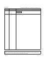
REVISIONS
* The manual number is given on the bottom left of the back cover.
Print Date
Mar., 1998
Jun., 2001
* Manual Number
Revision
IB (NA) 66838-A First edition
IB (NA) 66838-B • The manual layout was rearranged.
Models added
GOT-A900 Series
Japanese Manual Version IB-68944-C
This manual confers no industrial property rights or any rights of any other kind, nor does it confer any patent
licenses. Mitsubishi Electric Corporation cannot be held responsible for any problems involving industrial property
rights which may occur as a result of using the contents noted in this manual.
1998 MITSUBISHI ELECTRIC CORPORATION
A-5
A-5
INTRODUCTION
Thank you for purchasing the Mitsubishi Graphic Operation Terminal.
Before using the equipment, please read this manual carefully to develop full familiarity with the functions
and performance of the graphic operation terminal you have purchased, so as to ensure correct use.
Please forward a copy of this manual to the end user.
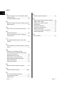
CONTENTS
SAFETY PRECAUTIONS ..............................................................................................................................A- 1
About the manuals ..........................................................................................................................................A- 8
Abbreviations and generic theism in this manual ..........................................................................................A-10
1. OVERVIEW
1- 1 to 1- 2
2. SYSTEM CONFIGURATION
2- 1 to 2- 4
2.1 Overall Configuration ............................................................................................................................... 2- 1
2.2 Instructions for System Configuration ..................................................................................................... 2- 2
3. SPECIFICATIONS
3- 1 to 3- 2
3.1 General Specifications............................................................................................................................. 3- 1
3.2 Performance Specifications..................................................................................................................... 3- 1
4. MONITORING SPECIFICATION
4- 1 to 4- 9
4.1 Monitoring Overview................................................................................................................................. 44.2 Monitorable Access Range and Device Specifying Method ................................................................... 44.2.1 Monitorable access range................................................................................................................ 44.2.2 How to specify devices when creating the monitor screen............................................................. 44.3 I/O Signals Transferred to/from the Master Module ............................................................................... 44.4 Remote Register Assignment ................................................................................................................. 45. PRE-OPERATION SETTINGS AND PROCEDURE
5.1
5.2
5.3
5.4
5.5
5- 1 to 5- 7
Pre-Operation Procedure ........................................................................................................................ 5Names of the Parts and Their Settings ................................................................................................... 5Handling Instructions ............................................................................................................................... 5Mounting Procedures .............................................................................................................................. 5Wiring Method.......................................................................................................................................... 5-
A-6
1
7
7
8
9
9
A-6
1
3
5
6
7
6. PROGRAMMING
6.1
6.2
6.3
6.4
6.5
6- 1 to 6- 4
System Configuration .............................................................................................................................. 6Relationships Between Corresponding Devices .................................................................................... 6Monitor Screen Examples ....................................................................................................................... 6A8GT-J61BT13 Switch Setting Example................................................................................................ 6Parameter Setting Example (Setting Using GX Developer)................................................................... 6-
7. TROUBLESHOOTING
1
1
2
4
4
7- 1 to 7- 5
7.1 LED-Indicated Error Causes and Their Corrective Actions..................................................................... 7- 1
7.2 Communication Error Occurs between Master Station and GOT........................................................... 7- 3
7.3 Method for Accelerating the Data Communication Processing Speed During Transient Transmission
................................................................................................................................................................... 7- 5
APPENDICES
APP- 1 to APP- 2
Appendix 1. Outline Dimension Drawing .................................................................................................APP- 1
Appendix 2. Calculating Formulas of the Transmission Delay Time When the A8GT-J61BT13 is Used
..............................................................................................................................................APP- 2
INDEX
A-7
Index- 1 to Index- 2
A-7
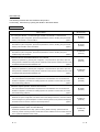
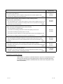
About Manuals
The following manuals are also related to this product.
In necessary, order them by quoting the details in the tables below.
Related Manuals
Manual Number
(Model Code)
Manual Name
CC-Link System Master • Local Module type AJ61BT11/A1SJ61BT11 User's Manual
Describes the system configuration, performance specifications, functions, handling, wiring and troubleshooting of the AJ61BT11 and A1SJ61BT11.
IB-66721
(13J872)
(Option)
CC-Link System Master • Local Module type AJ61QBT11/A1SJ61QBT11 User's Manual
Describes the system configuration, performance specifications, functions, handling, wiring and troubleshooting of the AJ61QB11 and A1SJ61QBT11.
IB-66722
(13J873)
(Option)
CC-Link System Master • Local Module type QJ61BT11 User’s Manual
Describes the system configuration, performance specifications, functions, handling, wiring and
troubleshooting of the QJ61BT11
SH-080016
(13JL91)
(Option)
A985GOT/A975GOT/A970GOT/A960GOT User's Manual
Explains the specifications, general system configuration, component devices, part names, option unit
loading methods, installation and wiring methods, maintenance and inspection methods, and error codes
of A985GOT/A975GOT/A970GOT/A960GOT unit.
SH-4005
(13JL70)
(Option)
A950GOT/A951GOT/A953GOT/A956GOT User's Manual
Explains the specifications, general system configuration, component devices, part names, option unit
loading methods, installation and wiring methods, maintenance and inspection methods, and error codes
of A950GOT/A951GOT/A953GOT/A956GOT unit.
SH-080018
(13JL92)
(Option)
A870GOT Graphic Operation Terminal User's Manual
This manual describes the specifications and performance of the A870GOT main unit as well as the
hardware configuration, procedures for installing optional units, operation in off-line mode, error codes,
and troubleshooting guidelines.
IB-66628
(13J830)
(Option)
A850GOT Graphic Operation Terminal User's Manual
This manual describes the specifications and performance of the A850GOT main unit as well as the
hardware configuration, procedures for installing optional units, operation in off-line mode, error codes,
and troubleshooting guidelines.
IB-66680
(13J901)
(Option)
GT Works Version 5/GT Designer Version 5 Reference Manual
Deals with the system configuration of GT Works Version 5/GT Designer Version 5, the screen makeup
of the GT Designer, the general description of various monitoring functions, the procedure for displaying
the monitor screen on the GOT, and how to use the help function.
SH-080117
(13JF95)
(Option)
GOT-A900 Series Operating Manual (GT Works Version 5/GT Designer Version 5
compatible Extended • Option Functions Manual)
Provides the specifications of the utility, system monitoring, ladder monitoring, special function unit
SH-080118
(13JU08)
monitoring, network monitoring functions and list editor functions available for the GOT-A900 series and
how to operate the dedicated monitor screen.
A-8
(Option)
A-8
Manual Number
(Model Code)
Manual Name
GOT-A900 Series User's Manual (GT Works Version 5/GT Designer Version 5 compatible
Connection System Manual)
Gives the specifications, system configuration, setting method and connection diagram of each
connection form available for the GOT-A900 series.
SH-080119
(13JR20)
(Option)
SW3NIW-A8GOTP Graphic Settings Software Package Operating Manual
(Monitor Screen Creation Manual)
This manual describes how to create monitor screens, the monitor functions available for the GOT, how
IB-66793
(13J927)
to set the monitor functions, precautions for creating monitor screens, and precautions for utilizing the
monitor data of the conventional GOT.
(Option)
SW3NIW-A8GOTP Graphic Settings Software Package Operating Manual
(Data Transmission/Debugging/Document Creation Manual)
This manual describes the following items.
IB-66794
(13J928)
1) Procedures for downloading project data to the GOT and uploading it from the GOT.
2) Procedures for installing the operating system in the GOT.
3) Procedures for using the A8GOTP as a virtual programmable controller and for debugging the GOT.
4) Procedures for outputting created monitor data as a completed document
(Option)
GOT800 Series Operating Manual (Expanded Functions Manual)
This manual describes the operation procedures for using the system monitor functions, monitor
functions for special function units, and the dedicated monitor screens used with the ladder monitor
functions.
IB-66796
(13J930)
(Option)
Type SW2IVD-GPPQ GPP Software package OPERATING MANUAL(Offline)
Describes the offline functions, such as the programming method, printout method and file maintenance,
of the SW2IVD-GPPQ
IB-66774
(13J921)
(Option)
GX Developer Version 6 Operating Manual
Describes the online functions of GX Developer including the programming procedure, printing out
procedure, monitoring procedure, and debugging procedure.
SH-080098
(13J989)
(Option)
Conformation to the EMC Directive
A8GT-J61BT13 conforms to the EMC Directive only when connected to the GOT
(with CE logo printed on the rating plate) which conforms to the EMC Directive.
For details of Conformation to the EMC Directive, refer to the using GOT User's
Manual (Hardware).
A-9
A-9
Abbreviations and generic terms in this manual
The following addreviations and symbols are used in this manual.
Abbreviation/Generic Name/Term
CC-Link
CC-Link
A8GT-J61BT13
communication
A8GT-J61BT15
module
A985GOT-V
A985GOT
A975GOT
GOT-A900
Series
A970GOT
A97*GOT
A960GOT
A956GOT
A956WGOT
A870GOT
GOT800
Series
A810GOT
A850GOT
GT Works
Version 5
GT Designer
Software
Version 5
GX Developer
GT Designer
Drawing
NIWSW
Software
A8GOTP
Personal computer
Master station
Local station
Remote I/O station
Remote device station
Remote station
Intelligent device station
Master/local module
Master module
Local module
Cyclic transmission
Transient transmission
RX
RY
RWw
RWr
A - 10
Description
Abbreviation for the Control & Communication Link system
Abbreviation of A8GT-J61BT13 type CC-Link communication module
Abbreviation of A8GT-J61BT15 type CC-Link communication module
Generic term of A985GOT-TBA-V and A985GOT-TBD-V
Generic term of A985GOT-TBA, A985GOT-TBD and A985GOT-TBA-EU
Generic term of A975GOT-TBA-B, A975GOT-TBD-B, A975GOT-TBA, A975GOTTBD and A975GOT-TBA-EU
Generic term of A970GOT-TBA-B A970GOT-TBD-B, A970GOT-TBA, A970GOTTBD, A970GOT-SBA, A970GOT-SBD, A970GOT-LBA, A970GOT-LBD, A970GOTTBA-EU and A970GOT-SBA-EU
Generic term of A975GOT and A970GOT
Generic term of A960GOT-EBA, A960GOT-EBD and A960GOT-EBA-EU
Generic term of A956GOT-TBD, A956GOT-SBD, A956GOT-LBD, A956GOT-TBDM3, A956GOT-SBD-M3 and A956GOT-LBD-M3
Abbreviation of A956WGOT-TBD
Generic term of A8GT-70GOT-EW, A8GT-70GOT-EB, A8GT-70GOT-SW, A8GT70GOT-SB, A8GT-70GOT-TW, A8GT-70GOT-TB
Abbreviation of A8GT-10GOT-C
Abbreviation of A850GOT-LWD, A850GOT-LBD, A850GOT-SWD, A850GOT-SBD,
A850GOT-LWD-M3, A850GOT-LBD-M3, A850GOT-SWD-M3, A850GOT-SBD-M3
Abbreviation of SW5D5C-GTWORKS-E software package
Generic term of SW5D5C-GOTR-PACKE software package and SW5D5C-GOTRPACKEV software package
Generic term of SW
D5C-GPPW-E/SW
D5F-GPPW-E software packages
Abbreviation of image creation software GT Designer for GOT900
Abbreviation of SW
NIW-A8GOTP software package
Personal computer where the corresponding software package is installed
Station which controls intelligent device, Local and Remote stations
Station which has a CPU and can communicate with the Master and other Local
stations
Slave station in the CC-Link system which can handle bit data only
Slave station in the CC-Link system which can handle bit data and word data
Generic name for remote I/O and remote device stations
Slave station in the CC-Link system which can make transient transmission, such
as the A8GT-J61BT13
Generic name for the QJ61BT11, AJ61BT11, AJ61QBT11, A1SJ61BT11 and
A1SJ61QBT11
Generic name for the QJ61BT11, AJ61BT11, AJ61QBT11, A1SJ61BT11 and
A1SJ61QBT11 when used as the Master station
Generic name for the QJ61BT11, AJ61BT11, AJ61QBT11, A1SJ61BT11 and
A1SJ61QBT11 when used as Local stations
Transmission method in which the contents of the remote inputs/outputs and
remote registers are updated periodically
Transmission method in which communication is made at any timing
Remote input
Remote output
Remote register (write area)
Remote register (read area)
A - 10
1 OVERVIEW
MELSEC-GOT
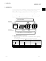
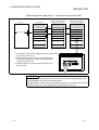
1. OVERVIEW
This user's manual includes specifications, monitoring method, handling information,
programming method and other instructions of the A8GT-J61BT13 CC-Link
communication module (hereinafter referred to as the "A8GT-J61BT13") used in the
Control Communication Link (hereinafter referred to as "CC-Link") system.
By connecting the A8GT-J61BT13 module to the GOT, it can perform a monitoring
operation as an intelligent device station (the number of occupied stations may be
selected between 1 and 4) in the CC-Link system.
The PLC CPU on the Master/local station of the CC-Link
system can be monitored.
Monitoring by
Transient Transmission
Intelligent device station
Local station
Master station
Remote device station
Monitoring by
Cyclic Transmission
CC-Link dedicated
cable
All remote inputs/outputs and remote registers assigned to
the Master station by CC-Link parameter setting can be monitored.
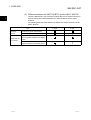
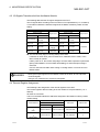
(1) PLC CPU that allows monitoring
Note that the types of the CPUs that can be monitored are different, depending
on the GOT used.
The following table lists the types of the CPUs that can be monitored.
: Can be monitored
: Cannot be monitored
CPU Connected TO When the GOT-A900 Series is used When the GOT800 Series is used
QCPU
(Q mode)
(A mode)
QnACPU
ACPU
Motion controller
1-1
1-1
1
1 OVERVIEW
MELSEC-GOT
(2) Difference between the A8GT-J61BT13 and the A8GT-J61BT15
There are differences in the monitoring methods that can be used as well as the
devices that can be monitored between the A8GT-J61BT13 and the A8GTJ61BT15.
The following table lists these differences between the A8GT-J61BT13 and the
A8GT-J61BT15.
1
Item
Monitoring
Monitoring by Cyclic Transmission
methods
Monitoring by Transient Transmission
When the A8GT-J61BT13
is used
When the A8GT-J61BT15
is used
The GOT’s remote inputs/outputs and
Devices that can
be monitored
remote registers assigned to the Master
station.
All remote inputs/outputs and remote
registers assigned to the Master station.
1-2
1-2
2 SYSTEM CONFIGURATION
MELSEC-GOT
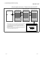
2. SYSTEM CONFIGURATION
This chapter describes the system configuration of the whole CC-Link system where
the A8GT-J61BT13 is used.
For equipment required for the GOT, refer to the user's manual of the GOT used.
2
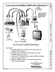
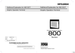
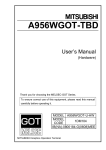
2.1 Overall Configuration
The following diagram shows the overall configuration for use of the A8GT-J61BT13.
Up to 26 GOTs using the A8GT-J61BT13 may be connected in relation to one master
module.
CC-Link Master/local module (Master station)
CC-Link Master/local module (Local station)
Terminal resistor
CC-Link dedicated cable
(Remote device station)
Terminal resistor
(Remote I/O station)
The number of occupied stations may be
selected between 1 and 4.
Remote inputs/outputs 32/128 points each
Remote registers
4/16 points each
GOT + A8GT-J61BT13
(Intelligent device station)
(Remote device station)
2-1
2-1
2 SYSTEM CONFIGURATION
MELSEC-GOT
2.2 Instructions for System Configuration
When using the A8GT-J61BT13, follow these system configuration instructions.
(1) GOTs which can use the A8GT-J61BT13
The following GOT models can use the A8GT-J61BT13.
Name
2
Model
A985GOT-V
A985GOT-TBA-V, A985GOT-TBD-V
A985GOT
A985GOT-TBA, A985GOT-TBD
A975GOT
A975GOT-TBA(-B), A975GOT-TBD(-B)
A970GOT
A970GOT-TBA(-B), A970GOT-TBD(-B), A970GOT-SBA,
A970GOT-SBD, A970GOT-LBA, A970GOT-LBD
A960GOT
A960GOT-EBA, A960GOT-EBD
A956WGOT
A956WGOT-TBD
A956GOT
A956GOT-TBD(-M3), A956GOT-SBD(-M3), A956GOT-LBD(-M3)
A870GOT
A8GT-70GOT-EW,A8GT-70GOT-EB,A8GT-70GOT-SW,A8GT70GOT-SB, A8GT-70GOT-TW,A8GT-70GOT-TB
A850GOT
A850GOT-LWD(-M3),A850GOT-LBD(-M3),A850GOT-SWD(-M3),
A850GOT-SBD(-M3)
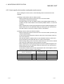
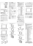
(2) Compatible software version
When creating the GOT screen or installing the operating system (OS), always use
the following software versions.
(a) GOT-A900 Series
SW0D5C-GTWORKS-E software version A or later
SW1D5C-GOTRE-PACK software version A or later
(b) GOT800 Series
Graphics software: SW3NIW-A8GOTP software version E or later
OS program: SW3NIW-A8SYSP software version E or later
Special module monitor data: SW3NIW-A8GMDP
The software version can be confirmed on the rating plate of the floppy disk of
the product.
SW
NIW-A8
P
SW
SW
D5C-GTWORKS-E or
D5C-GOTR-PACKE
DATE
9806A A
MITSUBISHI
MELSEC
3.5inch
SOFTWARE PACKAGE
MODEL
SW3NIW-A8GOTP
DATE
9801A E
1/6
Indicates the software version.
2-2
Indicates the software version.
2-2
2 SYSTEM CONFIGURATION
MELSEC-GOT
(3) Communication Driver Installed in the GOT
Install the following communication driver in the GOT.
CC-Link communication unit Used
Driver to Be Installed
A8GT-J61BT13
CC-LINK (ID)
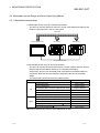
(4) Master/local module which can use the GOT loaded with the A8GT-J61BT13
(a) QJ61BT11
The QJ61BT11 is supported by function version A.
(b) AJ61(Q) BT11/A1SJ61(Q)BT11
The GOT loaded with the A8GT-J61BT13 may be used with the Master/local
module whose function version is B (Dec. 1997) or later and whose software
version is J (Jan. 1998) or later.
The GOT cannot be used with the Master/local module whose function and
software note that monitoring by cyclic transmission may only be performed
when the version of the module used are earlier than the above.
The function version is indicated in the DATE field of the rating plate.
<Large Type>
<Small Type>
MITSUBISHI
CPU UNIT
PROGRAMMABLE CONTROLLER
MODEL
DATE
DATE
9712 B
9712
B
MITSUBISHI ELECTRIC CORPORATION JAPAN
BD992D008H40
Year and month
of manufacture
MITSUBISHI ELECTRIC
Year and month
of manufacture
Function version
BD992D008H40
Function version
The function version is only indicated on version B or later.
The software version is indicated on the module version seal on the module front.
A1SJ61BT11
AJ61BT11
RUN
ERR.
MST
S MST
LOCAL
CPU R/W
E
SW
R
M/S
R PRM
O TIME
R LINE
156K
625K
2.5M
5M
10M
TEST
S0
S1
S2
B
R
A
T
E
RUN
ERR.
MST
S MST
LOCAL
CPU R/W
L RUN
L ERR.
STATION NO.
SW
M/S
PRM
TIME
LINE
E
R
R
O
R
SD
RD
MODE
T
E
S
T
Software version
L RUN
L ERR.
SD
RD
Hardware version
Software version
Hardware version
2-3
2-3
2 SYSTEM CONFIGURATION
MELSEC-GOT
(5) Utility function
The following table lists the GOT’s utility functions that can be used when the
A8GT-J61BT13 is in use.
: Usable
Item
When the A8GT-J61BT13 is used
Brightness/contrast adjustment
Screen & OS copy
Setup
Utility function
Self-test
Memory information
Clock
Screen cleanup
Password
: CPU communications check of the self-test function cannot be performed when
the GOT800 Series are in use.
(6) Extended•option functions
Refer to the manuals listed in the table below for the GOT’s extended • option
functions that can be used when the A8GT-J61BT13 is in use.
GOT Used
GOT-A900 Series
GOT800 Series
2-4
Manuals to refer to
GOT-A900 Series Operating Manual (GT Works Version5/GT
Designer Version5 compatible Extended•Option Functions Manual)
GOT800 Series Operating Manual (Expended Functions Manual)
2-4
3 SPECIFICATIONS
MELSEC-GOT
3. SPECIFICATIONS
This chapter provides the general and performance specifications and other
information of the A8GT-J61BT13.
3.1 General Specifications
The general specifications of the A8GT-J61BT13 changes according to the GOT used.
Refer to the user's manual of the GOT used.
3.2 Performance Specifications
3
The following table lists the performance specifications of the A8GT-J61BT13.
Item
Specifications
CC-Link station type
Intelligent device station
May be selected between 1 and 4.
Number of stations occupied
1 station: RX/RY 32 points each 1, RW write area 4 points each/read area all area
4 stations: RX/RY 128 points each 1, RW write area 16 points each /read area all area
Monitoring
Write from GOT:RX,RWs assigned to the GOT (depending on the number of stations occupied(Refer
by cyclic
to upper))
transmission
Resd to GOT :RX/RY(2048 points),RWw/RWr(512points)
Monitor
device
Monitoring
All devices of the PLC CPU on the Master/local station.
by transient
transmission
Transmission speed
156kbps/625kbps/2.5Mbps/5Mbps/10Mbps
Max. transmission distance
Depends on the transmission speed.
26
The max. number of modules connected depends on the configuration of the CC-Link system to be used.
Max. number of modules
For more details on the max. number of modules connected, refer to the CC-Link System Masterconnected
Local Module User’s Manual.
Connection cable
CC-Link dedicated cable
Terminal block
8-pin terminal block (M3.5 8 screws)
Applicable cable size
0.75mm2 to 2.00mm2
Applicable crimping terminal
RAV1.25-3, RAV2-3.5 (conforming to JIS C2805)
Power supply voltage
5V (Supplied from GOT)
0.25A
Included in the current consumption of the GOT:
Current consumption
A985GOT(-V), A975GOT, A970GOT, A960GOT, A956WGOT, A956GOT, A810GOT, A870GOT
Added to the current consumption of the GOT:
A850GOT
Outline dimensions
99mm(3.9inch)(H) 149mm(5.85inch)(W) 34mm(1.34 inch)(D)
Weight
0.21kg (0.46lb)
GOT-A900 Series
SW0D5C-GTWORKS-E Version A or later
SW0D5C-GOTRE-PACK Version A or later
Compatible software package
GOT800 Series
2
SW3NIW-A8GOTP Version E or later
SW3NIW-A8SYSP Version E or later
SW3NIW-A8GMDP
1
Each of the I/O signals (RX, RY) occupies 16 points of a system area within device points.
2
Be sure to use a software package that supports the GOT to be used.
For more details on the I/O signals, refer to Section 4.3.
For more information on the software packages that support the GOT, refer to the user’s manual of the GOT to be used.
3-1
3-1
3 SPECIFICATIONS
MELSEC-GOT
MEMO
3
3-2
3-2
4 MONITORING SPECIFICATION
MELSEC-GOT
4. MONITORING SPECIFICATION
4.1 Monitoring Overview
When the A8GT-J61BT13 is used, the GOT has the following two monitoring methods.
Monitoring Method
Contents
Monitoring by Transient Transmission
Devices of the PLC CPU on the CC-Link system
Master/local station are specified and monitored.
Monitoring by Cyclic Transmission
Remote inputs/outputs and remote registers
assigned to the Master station by CC-Link
parameter setting are specified and monitored.
CC-Link parameter setting sequence program 2 is
Advantage
required but GOT communication sequence
Data communication processing speed 1 is
program 2 is not needed. (For more information,
high.
refer to Chapter 5.)
•Write from the GOT (read command from the
master station) can be performed to only the
Disadvantage
Data communication processing speed 1 is lower
than that of cyclic transmission.
remote outputs and remote registers of the
master station assigned to the GOT and to the
GOT's internal registers.
•GOT communication sequence program 2 is
necessary.
1 For details of the data communication processing speed (object display speed),
refer to the GT Works Version 5/GT Designer Version 5 Reference Manual or
SW3NIW-A8GOTP operating manual (monitor screen creation).
2 This program is not needed if the CC-Link parameter setting sequence program
and GOT communication sequence program satisfy the following conditions.
• As the PLC CPU of the master station, use the QCPU (Q mode) or QnACPU
whose number given in the DATE field of the rating plate is "9707B" or later.
• Use GX Developer or SW2 -GPPW and make CC-Link parameter setting and
batch refresh device setting in the CC-Link setting on the package.
For details of the setting methods, refer to the CC-Link System Master/Local
Module User's Manual (Details).
POINT
In transient transmission, connection of several (five or more as a guideline)
intelligent device stations (GOTs and intelligent device units) reduces data
communication speed.
To raise data communication speed, increase the CC-Link system, for example,
and do not connect five or more intelligent device stations to a single CC-Link
system.
For more information on other methods for accelerating the data communication
speed, refer to Section 7.3.
4-1
4-1
4
4 MONITORING SPECIFICATION
MELSEC-GOT
(1) Monitoring by transient transmission
The devices of the PLC CPU on the CC-Link system Master/local station are
specified and monitored.
By merely specifying the devices to be monitored on the GOT, those devices can
be monitored without creating the GOT communication sequence program.
Monitorable
GOT communication sequence program
Master/local station
4
CC-Link dedicated cable
4-2
4-2
4 MONITORING SPECIFICATION
MELSEC-GOT
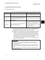
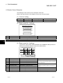
(2) Monitoring by Cyclic transmission
All remote inputs/outputs and remote registers assigned to the Master station by
CC-Link parameter setting can be specified and monitored.
(Not only the area assigned to the GOT in the Master station but also the regions
of the other stations can be monitored.)
This section describes the remote inputs, remote outputs, remote registers (write
area) and remote registers (read area) separately, but all data can be monitored
on the same screen.
[Remote inputs] ... Input function area of the GOT
PLC CPU
Master station
Remote inputs (RX)
RX0F to RX00
3)
[GOT+A8GT-J61BT13]
[GOT+A8GT-J61BT13]
Station 1: 1 station occupied
Intelligent device station
Station 2: 4 stations occupied
Intelligent device station
Remote inputs (RX)
2)
RX0F to RX00
Remote inputs (RX)
RX0F to RX00
2)
RX1F to RX10
RX1F to RX10
RX1F to RX10
RX2F to RX20
RX2F to RX20
RX2F to RX20
RX3F to RX30
RX3F to RX30
RX3F to RX30
RX4F to RX40
RX4F to RX40
RX4F to RX40
FROM
RX5F to RX50
2)
RX5F to RX50
RX5F to RX50
2)
RX6F to RX60
RX6F to RX60
RX6F to RX60
RX7F to RX70
RX7F to RX70
RX7F to RX70
RX8F to RX80
RX8F to RX80
RX8F to RX80
RX9F to RX90
RX9F to RX90
RX9F to RX90
RXAF to RXA0
RXAF to RXA0
RXAF to RXA0
to
to
to
RX7FF to RX7F0
RX7FF to RX7F0
RX7FF to RX7F0
1)
1) Store data into the remote inputs (RX) of the GOT.
(Touch switch function, etc.)
2) Data is stored by link scan into the remote inputs (RX)
assigned to the GOT of the Master station.
(Collected per link scan)
3) Read the data of the remote inputs (RX) to the PLC CPU.
OPERATION DIRECTIVE
POINT
The GOT can enter data (touch switch function, etc.) into the remote inputs (RX)
assigned to the GOT of the Master station.
Though the GOT cannot enter data (touch switch function, etc.) into the other
remote inputs (RX), it can display data (lamp display function, etc.).
4-3
4-3
4 MONITORING SPECIFICATION
MELSEC-GOT
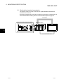
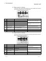
[Remote outputs] ... Display function area of the GOT
PLC CPU
1)
Master station
[GOT+A8GT-J61BT13]
Station 1:1 station occupied
Intelligent device station
[GOT+A8GT-J61BT13]
Station 2:4 stations occupied
Intelligent device station
Remote output (RY)
Remote output (RY)
Remote output (RY)
RY0F to RY00
RY0F to RY00
2)
2)
RY0F to RY00
RY1F to RY10
RY1F to RY10
RY1F to RY10
RY2F to RY20
RY2F to RY20
RY2F to RY20
RY3F to RY30
RY3F to RY30
RY3F to RY30
RY4F to RY40
RY4F to RY40
RY4F to RY40
TO
RY5F to RY50
2)
RY5F to RY50
2)
RY5F to RY50
RY6F to RY60
RY6F to RY60
RY6F to RY60
RY7F to RY70
RY7F to RY70
RY7F to RY70
RY8F to RY80
RY8F to RY80
RY8F to RY80
RY9F to RY90
RY9F to RY90
RY9F to RY90
RYAF to RYA0
RYAF to RYA0
RYAF to RYA0
to
to
to
RY7FF to RY7F0
RY7FF to RY7F0
RY7FF to RY7F0
3)
1) Store data into the remote outputs (RY) assigned to
the Master station by CC-Link parameter setting.
2) Data is stored into the remote outputs of the GOT by link
scan.
3) Display the specified remote outputs on the GOT.
(Lamp display function, etc.)
4-4
OPERATING STATUS
4-4
4 MONITORING SPECIFICATION
MELSEC-GOT
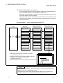
[Remote registers (read area)] ... Input function area of the GOT
PLC CPU
[GOT+A8GT-J61BT13]
Station 1: 1 station occupied
Intelligent device station
Master station
Remote registers (RWr)
[GOT+A8GT-J61BT13]
Station 2: 4 stations occupied
Intelligent device station
Remote registers (RWr)
2)
Remote registers (RWr)
2)
RWr0 to RWr3
RWr0 to RWr3
RWr0 to RWr3
RWr4 to RWr7
RWr4 to RWr7
RWr4 to RWr7
3)
FROM
RWr8 to RWrB
2)
RWr8 to RWrB
2)
RWr8 to RWrB
RWrC to RWrF
RWrC to RWrF
RWrC to RWrF
RWr10 to RWr13
RWr10 to RWr13
RWr10 to RWr13
RWr14 to RWr17
RWr14 to RWr17
RWr14 to RWr17
to
to
to
RWrFC to RWrFF
RWrFC to RWrFF
RWrFC to RWrFF
1)
1) Store data into the remote registers (read area) of the GOT.
(Value entry function, etc.)
2) Data is stored by link scan into the remote registers
(read area) assigned to the GOT of the Master station.
(Collected per link scan)
3) Read the data of the remote registers (read area) to
the PLC CPU.
PRODUCTION AMOUNT DIRECTIVE
LINE 1
LINE 2
LINE 3
120
50
POINT
The GOT can enter data (value entry function, etc.) into the remote registers (read
area) assigned to the GOT of the Master station.
Though the GOT cannot enter data (value entry function, etc.) into the other remote
registers (read area), it can display data (value display function, etc.).
4-5
4-5
4 MONITORING SPECIFICATION
MELSEC-GOT
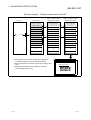
[Remote registers (write area)] ... Display function area of the GOT
PLC CPU
[GOT+A8GT-J61BT13]
Station 2: 4 stations occupied
Intelligent device station
[GOT+A8GT-J61BT13]
Station 1: 1 station occupied
Intelligent device station
Master station
Remote registers (RWw)
Remote registers (RWw)
2)
Remote registers (RWw)
2)
RWw0 to RWw3
RWw0 to RWw3
RWw0 to RWw3
RWw4 to RWw7
RWw4 to RWw7
RWw4 to RWw7
1)
to
RWw8 to RWwB
2)
RWw8 to RWwB
RWw8 to RWwB
2)
RWwC to RWwF
RWwC to RWwF
RWwC to RWwF
RWw10 to RWw13
RWw10 to RWw13
RWw10 to RWw13
RWw14 to RWw17
RWw14 to RWw17
RWw14 to RWw17
to
to
to
RWwFC to RWwFF
RWwFC to RWwFF
RWwFC to RWwFF
3)
1) Store data into the remote registers (write area) assigned
to the Master station by CC-Link parameter setting.
2) Data is stored into the remote registers (write area) of the
GOT by link scan.
3) Display the specified remote registers (write area) on the
GOT. (Value display function, etc.)
4-6
PRODUCTION CONDITION
LINE 1
LINE 2
LINE 3
115
46
74
4-6
4 MONITORING SPECIFICATION
MELSEC-GOT
4.2 Monitorable Access Range and Device Specifying Method
4.2.1 Monitorable access range
(1) Monitorable access range for Transient transmission
The GOT can monitor all devices of the PLC CPUs of the Master/local stations and
the GOT internal devices in the CC-Link system.
Monitorable
Intelligent device station
Local station
Master station
CC-Link dedicated cable
(2) Monitorable access range for Cyclic transmission
The GOT can monitor all remote inputs/outputs, remote registers and GOT internal
device assigned to the Master station by CC-Link parameter setting.
Among them, the GOT can write data (read command from the Master station) to
only the RX, RWr and GOT internal device assigned to the GOT of the Master
station.
The devices that can be monitored are indicated below.
Monitorable Devices
Remote inputs (RX)
Remote outputs (RY)
Bit
Word
Setting Device Range
RX0 to RX7FF
RY0 to RY7FF
Specified bits (RWw) of remote registers (write area)
RWw0 to RWwFF
Specified bits (RWr) of remote registers (read area)
RWr0 to RWrFF
GOT bit register (GB)
GB64 to GB1023
Bit designation of GOT data register (GD)
GD64 to GD1023
Remote registers (write area) (RWw)
RWw0 to RWwFF
Remote registers (read area) (RWr)
RWr0 to RWrFF
GOT data register (GD)
GD64 to GD1023
Converting GOT bit register to word (GB) 1
GB64 to GB1023
GOT special register (GS) 1
GS0 to GS511
Can be monitored only when the GOT-A900 Series is used.
4-7
4-7
4 MONITORING SPECIFICATION
MELSEC-GOT
4.2.2 How to specify devices when creating the monitor screen
When creating the monitor screen, set the following devices as the devices to be
specified.
(1) Setting of NW number and PLC station number
• When monitoring the devices of the PLC CPU on the other station
(monitoring by Transient transmission)
Set "NW number to 0" and "PLC station number to other station (station number: n)".
(n:station number of other station to be monitored (0:Master station, 1 to 64:Local
stations))
• When monitoring the remote inputs/outputs and remote registers assigned to the
Master station by CC-Link parameter setting (monitoring by Cyclic transmission)
Set "NW number to 0" and "PLC station number to host station".
(2) Setting of device names and device numbers
• When monitoring the devices of the PLC CPU on the other station (monitoring by
Transient transmission)
For the device names and device numbers, refer to the user's manual of the PLC
CPU to be monitored.
Note that the Graphics software does not check whether the device names and
device numbers set are usable with the PLC CPU to be monitored.
Before making setting, refer to the user's manual of the PLC CPU to be monitored
and confirm the usable device names and device numbers.
• When monitoring the remote inputs/outputs and remote registers assigned to the
Master station by CC-Link parameter setting (monitoring by Cyclic transmission)
Set the following device names.
As the device numbers of the remote inputs/outputs and remote registers, set the
addresses assigned by station number setting.
Device Name Set
Device to Be Monitored
4-8
on Graphics Software
Setting Device Range
Remote inputs
RX
X
X0 to X7FF
Remote outputs
RY
Y
Y0 to Y7FF
Remote registers (write area)
RWw
Ww
Ww0 to WwFF
Remote registers (read area)
RWr
Wr
Wr0 to WrFF
4-8
4 MONITORING SPECIFICATION
MELSEC-GOT
4.3 I/O Signals Transferred to/from the Master Module
The following table lists the I/O signals assigned to the GOT.
The I/O signals differ according to the set number of occupied stations (1 or 4 stations).
n in the table indicates the address assigned to the Master module by station number
setting.
Signal Direction:GOT
Master module
Signal Direction:Master module
Device number
Number of occupied stations
1 station
GOT
Device number
Number of occupied stations
Signal name
4 stations
1 station
4 stations
RXn0 to RXnF
RXn0 to
RX(n+6)F
User area
RYn0 to RYnF
RYn0 to
RY(n+6)F
RX(n+1)0 to
RX(n+1)A
RX(n+7)0 to
RX(n+7)A
Reserved
RY(n+1)0 to
RY(n+1)A
RY(n+7)0 to
RY(n+7)A
RX(n+1)B
RX(n+7)B
RX(n+1)C to
RX(n+1)F
RX(n+7)C to
RX(n+7)F
Remote ready
RY(n+1)B
flag 1
Reserved
RY(n+1)C to
RY(n+1)F
Signal name
RY(n+7)B
User area
Reserved
RY(n+7)C to
RY(n+7)F
1 The remote ready flag is on during startup of the GOT.
It switches on when GOT power is switched on, hardware reset is made, or the
GOT is ready to operate.
If GOT power is on, the remote ready flag is off when offline operation is performed
(during OS installation or screen data downloading) or while initial processing is
executed.
Use it for the interlock ladder when writing or reading data to or from the CC-Link
Master station.
DANGER
• Among the output signals from the Master module to the GOT, do not output the
reserved signals.
Doing so can cause the PLC system to misoperate.
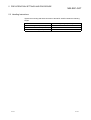
4.4 Remote Register Assignment
The following is the assignment of the remote registers of the GOT.
The remote registers differ according to the set number of occupied stations (1 or 4
stations).
All areas are use areas.
m and n in the table indicate the addresses assigned to the Master module by station
number setting.
Addresses
Transfer Direction
Number of occupied stations
1 station
Description
Default Value
User write area
0
User read area
0
4 stations
Master station
RWwm to RWwm+3 RWwm to RWwm+F
GOT
GOT
RWrn to RWrn+3
RWrn to RWrn+F
Master station
4-9
4-9
5 PRE-OPERATION SETTINGS AND PROCEDURE
MELSEC-GOT
5. PRE-OPERATION SETTINGS AND PROCEDURE
This chapter provides a pre-operation procedure, the names of the parts and their
settings, and the wiring method for the A8GT-J61BT13.
5.1 Pre-Operation Procedure
The following flowchart indicates a pre-operation procedure.
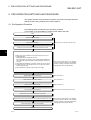
(1) Procedure up to downloading of monitor screen data to the GOT
Start
Wire the GOT power supply.
Supply power to the GOT.
Refer to the user's manual of the GOT used
Connect the GOT and Personal computer with the RS-232C cable.
5
Install the OS program installed in the Personal computer into the GOT.
1) Install ROM_BIOS.
ROM_BIOS is factory-installed into the GOT.
It must be installed only when the version of ROM_BIOS installed in the
GOT is older than that of ROM_BIOS currently installed in the personal
computer.
2) When ROM_BIOS installation is complete, reset the GOT power supply.
3) Install the basic OS, communication driver "CC-Link (ID)" and optional
function OS into the GOT.
4) When installation is complete, reset the GOT power supply.
⋅⋅⋅⋅⋅Refer to the GT Works Version 5 / GT Designer
Vsersion 5 Referrence Manual or the SW3NIWA8GOTP operating manual (Data transmission/
Debugging/Document Creation Manual)
Load the A8GT-J61BT13 to the GOT.
⋅⋅⋅⋅⋅Refer to Section 5.4
Set the switches of the A8GT-J61BT13.
⋅⋅⋅⋅⋅Refer to Section 5.2
Wire the CC-Link dedicated cable.
⋅⋅⋅⋅⋅Refer to Section 5.5
Load and wire the optional module.
⋅⋅⋅⋅⋅Refer to the user's manual of the GOT used
Switch on the system with which the GOT is connected.
Download the monitor screen data created on the personal computer to the GOT. ⋅⋅⋅⋅⋅Refer to the GT Works Version 5 / GT Designer
Vsersion 5 Referrence Manual or the SW3NIWA8GOTP operating manual (Data transmission/
Debugging/Document Creation Manual)
When downloading is complete, start monitoring.
Complete
5-1
5-1
5 PRE-OPERATION SETTINGS AND PROCEDURE
MELSEC-GOT
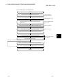
(2) Procedure up to CC-Link data link
Start
Load the Master and Local modules to the base units.
⋅⋅⋅⋅⋅Refer to the Master
module user's manual.
Install the GOT to the control box.
⋅⋅⋅⋅⋅Refer to the user's manual
of the GOT used
Check that the Master and Local modules operate independently.
(Hardware test)
⋅⋅⋅⋅⋅Refer to the Maste module
user's manual.
Connect the remote modules and GOT with CC-Link dedicated cable.
⋅⋅⋅⋅⋅Refer to Section 5.5
Set the station number switches of the A8GT-J61BT13.
⋅⋅⋅⋅⋅Refer to Section 5.2
Switch on the GOT, remote modules and Master module in this order.
Confirm the connection status of each module. (Line test)
Refer to the Maste module
user's manual.
Write a parameter setting program.
Monitoring by Transient transmission only
Write a communication program for monitoring by Cyclic transmission.
Start data link and monitor data on the GOT.
Complete
5-2
5-2
5
5 PRE-OPERATION SETTINGS AND PROCEDURE
MELSEC-GOT
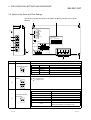
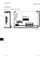
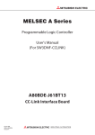
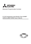
5.2 Names of the Parts and Their Settings
This section provides the names of the A8GT-J61BT13 parts and how to set the
switches.
7)
9)
7)
RUN
6)
L RUN
5)
SD
RD
01
EF 2
1)
89
67 A
345
MODE
MITSUBISHI
L ERR.
901
BCD
901
78
78
901
DATE
MITSUBISHI ELECTRIC CORPORATION
MADE IN JAPAN
456
3)
23
STATION NO.
456
23
DATALINK UNIT
MODEL
A8GT-J61BT13
456
2)
23
BD992C000H58
BAUDRATE
78
ON
1 2
4)
1
3
DA
SW ON
OFF
1 HOLD CLEAR
2
4
1
8)
7
NC
NC
6
8
4
DB
BD999C127H01
5
DG
2
SLD (FG1) NC
7)
8)
Number
Name
Description
Used to set the operating status of the module. (Factory setting:0)
Mode setting switch
8 9A
01
EF 2
3 45
67
1)
Number
Online
1
(Reserved)
2
Offline
BCD
3 to F
78
23
———
Disconnected from data link
———
Used to set the station number of the A8GT-J61BT13 between 1 and 64. (Factory setting: 01)
Use " 10" to set the tens.
Use " 1" to set the units.
456
78
901
23
(Reserved)
Description
Data link enabled and automatic return made
456
2)
901
Station number setting
switches
Name
0
Used to set the transmission speed of the module. (Factory setting:0)
23
456
78
3)
901
Transmission baudrate
setting switch
Number to be Set
Transmission Baudrate
0
156kbps
1
625kbps
2
2.5Mbps
3
5Mbps
4
10Mbps
5 to 9
5-3
Reserved (If the value you set is 5 to 9, the L.ERR
LED is lit to indicate a communication error.)
5-3
5 PRE-OPERATION SETTINGS AND PROCEDURE
Number
Name
MELSEC-GOT
Description
Used to set the operational conditions. (Factory setting:OFF)
Condition setting switches
ON 1 2
4)
Number
Switch Position
Setting Item
SW1
Number of occupied stations
SW2
Input data status of faulty data link station
ON
OFF
4 stations
1 station
Held
Cleared
Data link status can be conformed by the on/off statuses of the LEDs.
LED Name
RUN LED
L RUN LED
On:Indicates that communication is normal.
Off:Indicates a communication break (time excess error).
SD
SD LED
On:Indicates data transmission.
RD
RD LED
On:Indicates data receive.
L ERR.
LED
On:
Indicates a communication data error (CRC error).
Flicker: Indicates that any switch (1 to 4) position was changed while
power is on.
Off:
Indicates that communication is normal.
Indicator LEDs
RUN
L RUN
5)
Description
On:Indicates that the module is normal.
Off:Indicates a watchdog timer error.
L ERR.
6)
Connector
Connector for connection to the GOT
7)
Module fixing screws
Screws for installation to the GOT (M3
Terminal block
Terminal block for cable connection (M3
1
8)
3
DA
DG
2
4
DB
9)
5-4
5
3 screw)
8 screw)
7
NC
6
NC
8
SLD (FG1) NC
Rating plate
———
5-4
5 PRE-OPERATION SETTINGS AND PROCEDURE
MELSEC-GOT
5.3 Handling Instructions
Tighten the mounting and terminal screws of the A8GT-J61BT13 within the following
ranges.
Screw Location
5-5
Tightening Torque Range
Module mounting screw (M3 screw)
39 to 59N•cm
Terminal block terminal screw (M3 screw)
39 to 59N•cm
Terminal block mounting screw (M3.5 screw)
59 to 88N•cm
5-5
5 PRE-OPERATION SETTINGS AND PROCEDURE
MELSEC-GOT
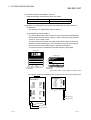
5.4 Mounting Procedures
This section provides the procedures to mount the A8GT-J61BT13 to and from the GOT.
(1) Mounting the A8GT-J61BT13 to the GOT-A900 Series
1) Fit the communication module securing fixtures in
the GOT main unit.
2) Mount the A8GT-J61BT13 on the GOT interface.
3) Tighten and fix the mounting screws (3 pcs.) of the
communication module in the specified torque
range. (39 to 59 N•cm)
4) To remove the unit, reverse the installation
procedure.
(2) Mounting the A8GT-J61BT13 to the GOT800 Series
1) Fit the A8GT-J61BT13 to the mounting section of
the GOT.
2) Tighten the module fixing screws (3 pcs.) to within
the specified torque range (39 to 59N•cm).
3) To remove the unit, reverse the installation
procedure.
5-6
5-6
5 PRE-OPERATION SETTINGS AND PROCEDURE
MELSEC-GOT
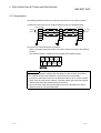
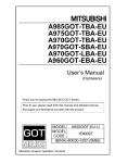
5.5 Wiring Method
The following diagram shows how to wire the GOT and CC-Link system modules.
(1) Wiring the GOT and CC-Link system modules by CC-Link dedicated cable
Master module
Terminal
resistor
DA
DB
DG
GOT
I/O module, etc.
DA
DA
DB
DB
(Blue)
(Yellow)
(White)
DG
CC-Link dedicated cable
SLD
FG
SLD
FG1
Terminal
resistor
DG
CC-Link dedicated cable
SLD
FG
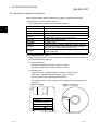
(2) Connection of terminal resistor to the GOT
When connecting a terminal resistor to the GOT, always connect it in the following
position.
The terminal resistor is contained in the package of the Master module.
DA
DG
DB
NC
SLD
NC
FG1
NC
Terminal resistor
POINT
• The "terminal resistors" supplied with the Master module must be connected to
the modules at both ends of data link. (Connect them across DA-DB.)
• Connect the shield wire of the CC-Link dedicated cable to "SLD" of each module.
Since "SLD" is connected to "FG/FG1" internally, always ground the FG terminal
and FG1 terminal to the protective ground conductor.
• The FG terminal of the GOT power supply and the FG1 terminal of the A8GTJ61BT13 must be connected separately.
5-7
5-7
6 PROGRAMMING
MELSEC-GOT
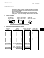
6. PROGRAMMING
The programming example described in this section is designed to make parameter
setting to the master module and communication between the GOT and remote I/O
station in the following system.
Refer to the CC-Link System Remote I/O Module User's Manual (Details) for the
remote I/O station, and to the CC-Link System Master/Local Module User's Manual
(Details) for details of the parameter setting made to the master module.
6.1 System Configuration
A975GOT + A8GT-J61BT13
Station 1:1 station occupied
PLC (Q06HCPU)
QJ61BT11:Station 0
AJ65BTB1-16DT
Station 2:1 station occupied
CC-Link dedicated cable
6.2 Relationships Between Corresponding Devices
[Q06HCPU]
[QJ61BT11]
Station
Master station
PLC CPU
Address
[A975GOT + A8GT-J61BT13]
Station 1:1station occupied
Intelligent device station
[AJ65BTB1-16DT]
Station 1:1station occupied
Remote I/O station
Remote inputs (RX)
Remote inputs (RX)
Remote inputs (RX)
M0 to M15
E0H
RX0F to RX00
RX0F to RX00
RX0F to RX00
M16 to M31
E1H
RX1F to RX10
RX1F to RX10
RX1F to RX10
M32 to M47
E3H
RX2F to RX20
RX2F to RX20
M48 to M63
E4H
RX3F to RX30
RX3F to RX30
Address
Remote outputs(RY)
Remote outputs(RY)
M112 to M127
160H
RY0F to RY00
RY0F to RY00
RY0F to RY00
M128 to M143
161H
RY1F to RY10
RY1F to RY10
RY1F to RY10
M144 to M159
162H
RY2F to RY20
RY2F to RY20
M160 to M175
163H
RY3F to RY30
RY3F to RY30
Remote registers (RWw)
Remote registers (RWw)
Address
D100 to D103
1E0H to 1E3H RWw0 to RWw3
Address
D200 to D203
6-1
Remote outputs(RY)
Remote registers (RWr)
2E0H to 2E3H
RWr0 to RWr3
RWw0 to RWw3
Remote registers (RWr)
RWr0 to RWr3
6-1
6
6 PROGRAMMING
MELSEC-GOT
6.3 Monitor Screen Examples
The following are the monitor screen examples of the GOT.
Refer to the help function of GT Designer for the way to set each object.
(1) Common setting
Setting Item
PLC Type
GOT Type
Base Screen Switching Device
Settings
MELSEC-QnA,Q
A97*GOT/GT SoftGOT
D300
(2) Base screen No. 1 settings
MAIN MANU OF BLOCK A
No.
LINE CONDITIONS
1)
PRODUCTION CONDITIONS
2)
OTHER BLOCK CONDITIONS
3)
Object Function to Be Set
Setting
Operation
1)
Touch key function
Base screen switching fixed value: 2
Setting made to switch to base screen No. 2.
2)
Touch key function
Base screen switching fixed value: 3
Setting made to switch to base screen No. 3.
3)
Touch key function
Base screen switching fixed value: 4
Setting made to switch to base screen No. 4.
6
(3) Base screen No. 2 settings
The devices of the master station assigned to the AJ65BTB1-16DT (remote I/O
station) are monitored. (Monitor using cyclic transmission)
LINE CONDITIONS OF BLOCK A
LINE 1
No.
Object Function to Be Set
LINE 2
LINE 3
OPERATING
CONDITON
1)
2)
3)
TROUBLE
OCCURRENCE
4)
5)
6)
MAIN
PRODUCTION
CONDITIONS
OTHER
BLOCKS
7)
8)
9)
Setting
Operation
1)
Lamp display function
Monitor device: X0 (RX0) to M0
2)
Lamp display function
Monitor device: X1 (RX1) to M1
3)
Lamp display function
Monitor device: X2 (RX2) to M2
4)
Lamp display function
Monitor device: Y0 (RY0) from M112
5)
Lamp display function
Monitor device: Y1 (RY1) from M113
6)
Lamp display function
Monitor device: Y2 (RY2) from M114
Settings made to display on the GOT the fault
occurrence information output to the remote I/O
station.
7)
Touch key function
Screen switching device: Fixed at 1
Setting made to switch to base screen No. 1.
8)
Touch key function
Screen switching device: Fixed at 3
Setting made to switch to base screen No. 3.
9)
Touch key function
Screen switching device: Fixed at 4
Setting made to switch to base screen No. 4.
6-2
Settings made for the remote I/O station to display
on the GOT the line operating statuses (ON/OFF)
stored in M0 to M3.
6-2
6 PROGRAMMING
MELSEC-GOT
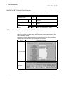
(4) Base screen No. 3 settings
The devices of the master station assigned to the GOT (intelligent device station)
are monitored. (Monitor using cyclic transmission)
PRODUCTION CONDITION OF BLOCK A
LINE 1
LINE 2
LINE 3
1)
2)
3)
4)
5)
6)
PLANNED
QUANTITY
PRODUCED
QUANTITY
No.
7)
8)
TROUBLE
OCCURRENCE
EMERGENCY STOP
MAIN
LINE
CONDITION
OTHER
BLOCKS
9)
10)
11)
Object Function to Be Set
Setting
Operation
1)
Numerical input function
Write device Wr4 to D204
2)
Numerical input function
Write device Wr5 to D205
3)
Numerical input function
Write device Wr6 to D206
4)
Numerical display function
Write device Ww4 from 104
5)
Numerical display function
Write device Ww5 from 105
6)
Numerical display function
Write device Ww6 from 106
7)
Lamp display function
Monitor device: Y20 (RY20) from M144
Settings made to display on the GOT the fault
occurrence information stored in M144.
8)
Touch key function
Bit ALT: X20 (RX20) to M32
Setting made to store the ON/OFF information
entered with the touch key function into M32.
Settings made to store the values entered with the
numerical input function into D204-D206.
Settings made to display the values stored in
D104-D106.
9)
Touch key function
Screen switching device: Fixed at 1
Setting made to switch to base screen No. 1.
10)
Touch key function
Screen switching device: Fixed at 2
Setting made to switch to base screen No. 2.
11)
Touch key function
Screen switching device: Fixed at 4
Setting made to switch to base screen No. 4.
(5) Base screen No. 4 settings
The PLC CPU devices of the master station are directly specified and monitored.
(Monitor using Transient transmission)
PRODUCTION CONDITIONS OF OTHER BLOCKS
BLOCK B
OPERATING
CONDITION
PROCUCED
QUANTITY
PRODUCTION
INCREASE
REQUEST
No.
BLOCK C
1)
3)
2)
4)
5)
6)
MAIN
LINE
CONDITION
PRODUCTION
CONDITION
7)
8)
9)
Object Function to Be Set
Setting
Operation
1)
Lamp display function
Monitor device: M200
2)
Lamp display function
Monitor device: M201
3)
Numerical input function
Write device D300
4)
Numerical input function
Write device D301
5)
Touch key function
Bit ALT: M202
6)
Touch key function
Bit ALT: M204
7)
Touch key function
Screen switching device: Fixed at 1
Setting made to switch to base screen No. 1.
8)
Touch key function
Screen switching device: Fixed at 2
Setting made to switch to base screen No. 2.
9)
Touch key function
Screen switching device: Fixed at 3
Setting made to switch to base screen No. 3.
6-3
Settings made to display on the GOT the values
stored in M200-M201.
Settings made to store the values entered with the
numerical input function into D300-D301.
Settings made to store the ON/OFF information
entered with the touch key function into M200M201.
6-3
6 PROGRAMMING
MELSEC-GOT
6.4 A8GT-J61BT13 Switch Setting Example
The following is an example of setting the A8GT-J61BT13 switches.
Switch Name
Setting
mode setting switch
0
Station number setting
10
0
switches
1
1
Transmission baudrate setting
switch
0
Description
Online (data link enabled and with automatic
return)
Station No. 1
156kBPS
Condition setting
SW1
OFF
Input data state of data link error station: Clear
switches
SW2
OFF
Number of occupied stations: 1 station
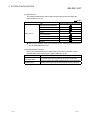
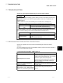
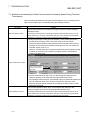
6.5 Parameter Setting Example (Setting Using GX Developer)
In the network parameter CC-Link list setting, set the first I/O No., total number of
stations connected, remote I/O refresh devices, remote register refresh devices, and
station information setting.
Setting the items of the following CC-Link list setting and CC-Link station information
makes a GOT communication sequence program unnecessary.
Item
Setting Screen Example
CC-Link list setting
CC-Link station
information
6-4
6-4
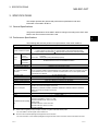
7 TROUBLESHOOTING
MELSEC-GOT
7. TROUBLESHOOTING
This section gives simple troubleshooting for use of the A8GT-J61BT13.
POINT
By setting the alarm list display (system alarm) function to the display screen using
the graphics software, the GOT can quickly detect a link error, in addition to the
following errors.
When a link error occurs, the following error code and error messages are
displayed in the display field of the alarm list display (system alarm) function.
Error code
402
Message
• Communication disable (GOT800 Series)
• Communication time-out (GOT-A900 Series)
For more details on how to set up the alarm list display (system alarm) function and
the contents of display, refer to the manuals listed in the table below.
GOT Used
GOT-A900 Series
GOT800 Series
Manuals to refer to
GT Designer Help function
SW NIW-A8GOTP Operating Manual (Monitor
Screen Creation Manual)
7.1 LED-Indicated Error Causes and Their Corrective Actions
This section explains how to check errors indicated by the LEDs of the A8GTJ61BT13.
For errors related to the PLC CPU and Master module, refer to the user's manuals of
the PLC CPU and Master module.
(1) If the RUN LED of the A8GT-J61BT13 goes off
Cause
Corrective Action
Check the special link registers of the Master module
to make sure that the watchdog timer error occurred
Watchdog timer error occurred.
and switch on power of the GOT again 1.
If the RUN LED is not lit after power is switched on
again, the hardware may be faulty. Consult your
sales representative.
Power is not supplied to the GOT or
Supply power to the GOT and check the voltage of
voltage is insufficient.
the power supply.
Switch setting is outside the specified
range (mode 2 or 4 to F, station number 0
or 65 or more, transmission speed 5 to 9).
7-1
Correct the switch setting and switch power on
again 1.
7-1
7
7 TROUBLESHOOTING
MELSEC-GOT
(2) If the L RUN LED of the A8GT-J61BT13 goes off
Cause
CC-Link dedicated cable is broken or
shorted.
Master station stopped link.
Corrective Action
Check and repair the CC-Link dedicated cable.
Check for an error at the Master station.
Switch power on again 1 after correcting the station
Station number was repeated.
number setting of the module of which station number
was repeated.
GOT parameters have not been set.
Correct the GOT parameter setting and switch power of
the GOT again 1.
Power is not supplied to the GOT or
Supply power to the GOT and check the voltage of the
voltage is insufficient.
power supply.
Switch setting is outside the specified
range (mode 2 or 4 to F, station number 0
or 65 or more, transmission speed 5 to 9).
Correct the switch setting and switch power on
again 1.
(3) If the L ERR LED of the A8GT-J61BT13 flickers
Cause
Corrective Action
Return the mode, station number or transmission
Mode, station number or transmission
speed switch setting was changed during
normal operation.
speed switch setting to the previous position and
switch power on again 1.
If the L RUN LED is not lit after switching power on
again, the hardware may be faulty. Consult your
sales representative.
Station number or transmission speed
switch is faulty.
7
If the L ERR LED begins to flicker though switch setting
was not changed during operation, the hardware may
be faulty. Consult your sales representative.
(4) If the L ERR LED of the A8GT-J61BT13 is lit
Cause
Switch setting is outside the specified
range (mode 2 or 4 to F, station number 0
or 65 or more, transmission speed 5 to 9).
Terminal resistors are left unconnected.
Corrective Action
Correct the switch setting and switch power on
again 1.
Check that the terminal resistors are connected. If not,
connect them and switch power on again 1.
• Connect both ends of the shield wire of the CC-Link
dedicated cable to ground (earth conductors
A8GT-J61BT13 or CC-Link dedicated
cable are affected by noise.
separately) via SLD and FG1 of each module.
• Securely connect the FG terminal of the module to
ground.
• Securely ground the piping when running cables in
piping.
1: Switch power on again:Switch power on again or turn on the reset switch.
7-2
7-2
7 TROUBLESHOOTING
MELSEC-GOT
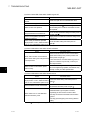
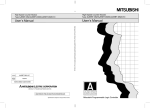
7.2 Communication Error Occurs between Master Station and GOT
If any repeated station number bit in any of the link special registers SW0098 to
SW009B (repeated station number status) switches on, check the GOT of the
corresponding station number in the following flowchart.
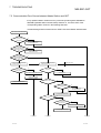
Troubleshooting flowchart used when the "ERR" LED of the Master station flickers
"ERR" LED of master station flickers
Parameter
setting match system
configuration?
N
Correct parameter setting
or system configuration.
Y
Any of Master
station link special registers
SW0080 to SW0083 (other
station data link status)
ON?
N
Master station faulty
Y
Any of Master
station link special registers
SW0098 to SW009B (repeated
station number status)
ON?
N
Y
Check the module corresponding
to the bit switched on.
Station number switch
setting correct?
Y
Master side check
Check the module corresponding
to the bit switched on.
N
Power on?
Correct station number switch setting.
GOT side check
N
Switch power on.
Y
Switch power on again
or turn on reset switch.
"POWER" LED lit?
N
Corresponding module faulty
Y
Is supply voltage
within specified range?
N
Set supply voltage to
within specified range.
Y
Corresponding module faulty
"RD" LED lit?
Y
N
Communication cable
wired correctly*1?
Y
N
Correct communication cable wiring.
Corresponding module faulty
To next page
7-3
To next page
To next page
7-3
7 TROUBLESHOOTING
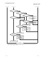
From preceding page
MELSEC-GOT
From preceding page
"L RUN" LED lit?
From preceding page
N
Y
"SD" LED lit (flicker)?
N
Y
Baudrate setting correct?
"SD" LED lit (flicker)?
Y
Y
N
N
Correct baudrate setting.
Switch power on again
or turn on reset switch.
Corresponding module faulty
Communication cable
wiring correct*1?
Y
N
Correct communication cable wiring.
Corresponding module faulty
(Baudrate switch)
Station number
switch setting correct
(not repeated)?
N
Correct station number setting.
Y
Switch power on again
or turn on reset switch.
Corresponding module faulty
(Station number switches)
Station number
switch setting correct
(not repeated)?
N
Correct station number setting.
Y
Switch power on again
or turn on reset switch.
Corresponding module faulty
(Station number switches)
Complete
*1: Check for short circuit, reverse connection, wire breakage, no terminal resistor, improper FG connection, improper overall
distance and improper interstation distance.
7-4
7-4
7 TROUBLESHOOTING
MELSEC-GOT
7.3 Method for Accelerating the Data Communication Processing Speed During Transient
Transmission
When monitoring is performed during transient transmission, the processing speed of
data communication can be accelerated using the following methods.
CPU types
Method
Insert a COM instruction in the sequence program of the CPU that exchanges
data with the GOT.
When the ACPU is used
By inserting a COM instruction, general data request is performed between the CC-Link
module and the CPU. However, note that the scan time of the sequence program will be
extended by a maximum of about 3 ms if a COM instruction is inserted.
(1) Using GX Developer, select [PLC Parameters] - [PLC system] and set the
general data processing count to the same count set for the module
performing general data processing that has been mounted to the QnACPU.
(Example: If one serial communication module and one CC-Link module are
mounted, set the count to “2.”)
However, note that each time a module that performs general data processing
is added, the scan time of the sequence program will be is extended by a
maximum of about 3 ms.
When the QnACPU is used
Set this count to the same
count set for the module
performing general data
processing.
(2) Insert a COM instruction (which turns on the special relay SM775) in the
sequence program of the CPU that exchanges data with the GOT.
By inserting a COM instruction, general data request is performed between the
CC-Link module and the CPU. However, note that the scan time of the
sequence program will be extended by a maximum of about 3 ms if a COM
instruction is inserted.
Insert a COM instruction (which turns on the special relay SM775) in the
sequence program of the CPU that exchanges data with the GOT.
When the QCPU is used
By inserting a COM instruction, general data request is performed between the CC-Link
module and the CPU. However, note that the scan time of the sequence program will be
extended by a maximum of about 3 ms if a COM instruction is inserted.
7-5
7-5
APPENDICES
MELSEC-GOT
APPENDICES
Appendix 1. Outline Dimension Drawing
RUN
L RUN
SD
RD
MODE
MITSUBISHI
L ERR.
78
901
78
901
78
901
BCD
DATE
MITSUBISHI ELECTRIC CORPORATION
MADE IN JAPAN
BD992C000H58
CAUTION
456
23
STATION NO.
456
23
DATALINK UNIT
MODEL
A8GT-J61BT13
456
23
99(3.9)
01
EF 2
89
67 A
345
BAUDRATE
ON
Do not mount nor dismount
a module while the power
is supplied.
1 2
1
SW ON
OFF
1 HOLD CLEAR
2
4
1
34(1.34)
5
(0.2)
3
DA
2
4
DB
BD999C127H01
5
DG
7
NC
NC
6
8
SLD (FG1)
NC
149(5.87)
Unit:mm(inch)
APP
APP - 1
APP - 1
APPENDICES
MELSEC-GOT
Appendix 2. Calculating Formulas of the Transmission Delay Time When the A8GTJ61BT13 is Used
The following explains the calculating formulas of the transmission delay time when the
A8GT-J61BT13 is used (when the GOT is an intelligent device station).
(1) During cyclic transmission
(a) Calculating formula
SM + LS 3 + 100 (processing time of the intelligent device station: 100 ms)
= Transmission delay time of the intelligent device station
SM : Scan time of the Master station’s sequence program
LS : Link scan time
(b) Example of calculation
When SM: 10 ms, LS: 5 ms
10 + 5 3 + 100 = 125 (ms)
(2) During transient transmission
(a) Calculating formula
MB + Processing time of the intelligent device station
= Transmission delay time of the intelligent device station
+ SM + LS
1) MB = {SM + LS 2 + (request data count + 16) / 16 LS +
+ (response data count + 16) / 72 LS +
+ bps constant} N
Request data count: (Number of object points + (Number of object points
/ 19) 1) 6
Response data count: (Number of object points + (Number of object
points / 19) 1) 2
2) Processing time of the intelligent device station = 90 (Number of
object points / 19) 1
1 Round-up
(b) Example of calculation
When SM: 10 ms, LS: 5 ms, the numeric value display function is set to 18
points
Request data count: 114 = (18 + (18 / 19)) 6
Response data count: 38 = (18 + (18 / 19)) 2
: LS 5 ms, : LS 5 ms, N: 7
MB = 10 + 5 2 + (114 + 16) / 16 5 + 5 + 10 + 5 + (38 + 16) / 72
= 10 + 10 + 45 + 5 + 10 + 5 + 5 + 5 + 35
= 130 (ms)
Processing time of the intelligent device station = 90
= 90 (18 / 19)
= 90 (ms)
130 + 90 = 210 (ms)
5+5+5
7
(Number of object points / 19)
Differences in the transmission delay time, depending on the number of object points
(when calculated using the conditions shown above)
APP - 2
Number of object points set
Transmission delay time
38 points
335 ms
57 points
480 ms
76 points
605 ms
95 points
737 ms
APP - 2
APP
INDEX
Ind
[C]
Communication error occurs between master
station and GOT .............................................. 7-3
Compatible software version........................... 2-2
[D]
Difference between the A8GT-J61BT13 and the
A8GT-J61BT15 ............................................... 1-2
[G]
GOTs which can use the A8GT-J61BT13...... 2-2
[H]
Handling instructions....................................... 5-5
How to specify devices when creating the
monitor screen................................................. 4-8
[R]
Remote register assignment ...........................4-9
[S]
Setting of device names and device numbers ......4-8
Setting of NW number .....................................4-8
Setting of PLC station number ........................4-8
Specifications ...................................................3-1
General specifications .....................................3-1
Performance specifications .............................3-1
System configuration .......................................2-1
Instructions for system configuration...............2-2
Overall configuration........................................2-1
[W]
Wiring method..................................................5-7
[I]
I/O signals transferred to/from the master
module ............................................................. 4-9
[L]
LED-indicated error causes and their corrective
actions.............................................................. 7-1
[M]
Method for Accelerating the Data
Communication Processing Speed During
Transient Transmission ................................... 7-5
Monitorable Access range .............................. 4-7
Monitoring by cyclic transmission ................... 4-1
Monitoring by transient transmission .............. 4-1
Monitor specification........................................ 4-1
Mounting procedures ...................................... 5-6
[N]
Names of the parts and their settings............. 5-3
[O]
Outline dimension drawing..........................App-1
[P]
PLC CPU that allows monitoring .................... 1-1
Pre-operation procedure ................................. 5-1
Programming................................................... 6-1
Index - 1
Index - 1
MEMO
Ind
Index - 2
Index - 2
WARRANTY
Please confirm the following product warranty details before starting use.
1. Gratis Warranty Term and Gratis Warranty Range
If any faults or defects (hereinafter "Failure") found to be the responsibility of Mitsubishi occurs during use of the product
within the gratis warranty term, the product shall be repaired at no cost via the dealer or Mitsubishi Service Company.
Note that if repairs are required at a site overseas, on a detached island or remote place, expenses to dispatch an
engineer shall be charged for.
[Gratis Warranty Term]
The gratis warranty term of the product shall be for one year after the date of purchase or delivery to a designated
place.
Note that after manufacture and shipment from Mitsubishi, the maximum distribution period shall be six (6) months, and
the longest gratis warranty term after manufacturing shall be eighteen (18) months. The gratis warranty term of repair
parts shall not exceed the gratis warranty term before repairs.
[Gratis Warranty Range]
(1) The range shall be limited to normal use within the usage state, usage methods and usage environment, etc.,
which follow the conditions and precautions, etc., given in the instruction manual, user's manual and caution labels
on the product.
(2) Even within the gratis warranty term, repairs shall be charged for in the following cases.
1. Failure occurring from inappropriate storage or handling, carelessness or negligence by the user. Failure caused
by the user's hardware or software design.
2. Failure caused by unapproved modifications, etc., to the product by the user.
3. When the Mitsubishi product is assembled into a user's device, Failure that could have been avoided if functions
or structures, judged as necessary in the legal safety measures the user's device is subject to or as necessary
by industry standards, had been provided.
4. Failure that could have been avoided if consumable parts (battery, backlight, fuse, etc.) designated in the
instruction manual had been correctly serviced or replaced.
5. Failure caused by external irresistible forces such as fires or abnormal voltages, and Failure caused by force
majeure such as earthquakes, lightning, wind and water damage.
6. Failure caused by reasons unpredictable by scientific technology standards at time of shipment from Mitsubishi.
7. Any other failure found not to be the responsibility of Mitsubishi or the user.
2. Onerous repair term after discontinuation of production
(1) Mitsubishi shall accept onerous product repairs for seven (7) years after production of the product is discontinued.
Discontinuation of production shall be notified with Mitsubishi Technical Bulletins, etc.
(2) Product supply (including repair parts) is not possible after production is discontinued.
3. Overseas service
Overseas, repairs shall be accepted by Mitsubishi's local overseas FA Center. Note that the repair conditions at each FA
Center may differ.
4. Exclusion of chance loss and secondary loss from warranty liability
Regardless of the gratis warranty term, Mitsubishi shall not be liable for compensation to damages caused by any cause
found not to be the responsibility of Mitsubishi, chance losses, lost profits incurred to the user by Failures of Mitsubishi
products, damages and secondary damages caused from special reasons regardless of Mitsubishi's expectations,
compensation for accidents, and compensation for damages to products other than Mitsubishi products and other duties.
5. Changes in product specifications
The specifications given in the catalogs, manuals or technical documents are subject to change without prior notice.
6. Product application
(1) In using the Mitsubishi MELSEC programmable logic controller, the usage conditions shall be that the application will
not lead to a major accident even if any problem or fault should occur in the programmable logic controller device, and
that backup and fail-safe functions are systematically provided outside of the device for any problem or fault.
(2) The Mitsubishi general-purpose programmable logic controller has been designed and manufactured for applications
in general industries, etc. Thus, applications in which the public could be affected such as in nuclear power plants and
other power plants operated by respective power companies, and applications in which a special quality assurance
system is required, such as for Railway companies or National Defense purposes shall be excluded from the
programmable logic controller applications.
Note that even with these applications, if the user approves that the application is to be limited and a special quality is
not required, application shall be possible.
When considering use in aircraft, medical applications, railways, incineration and fuel devices, manned transport
devices, equipment for recreation and amusement, and safety devices, in which human life or assets could be greatly
affected and for which a particularly high reliability is required in terms of safety and control system, please consult
with Mitsubishi and discuss the required specifications.
MITSUBISHI ELECTRIC
HEADQUARTERS
EUROPEAN REPRESENTATIVES
EUROPEAN REPRESENTATIVES
MITSUBISHI ELECTRIC EUROPE B.V.
EUROPE
German Branch
Gothaer Straße 8
D-40880 Ratingen
Phone: +49 (0)2102 / 486-0
Fax: +49 (0)2102 / 486-1120
MITSUBISHIELECTRICEUROPEB.V.-org.sl. CZECH REP.
Czech Branch
Avenir Business Park, Radlická 714/113a
CZ-158 00 Praha 5
Phone: +420 - 251 551 470
Fax: +420 - 251-551-471
MITSUBISHI ELECTRIC EUROPE B.V.
FRANCE
French Branch
25, Boulevard des Bouvets
F-92741 Nanterre Cedex
Phone: +33 (0)1 / 55 68 55 68
Fax: +33 (0)1 / 55 68 57 57
MITSUBISHI ELECTRIC EUROPE B.V.
IRELAND
Irish Branch
Westgate Business Park, Ballymount
IRL-Dublin 24
Phone: +353 (0)1 4198800
Fax: +353 (0)1 4198890
MITSUBISHI ELECTRIC EUROPE B.V.
ITALY
Italian Branch
Viale Colleoni 7
I-20041 Agrate Brianza (MB)
Phone: +39 039 / 60 53 1
Fax: +39 039 / 60 53 312
MITSUBISHI ELECTRIC EUROPE B.V.
POLAND
Poland Branch
Krakowska 50
PL-32-083 Balice
Phone: +48 (0)12 / 630 47 00
Fax: +48 (0)12 / 630 47 01
MITSUBISHI ELECTRIC EUROPE B.V.
RUSSIA
52, bld. 3 Kosmodamianskaya nab 8 floor
RU-115054 Мoscow
Phone: +7 495 721-2070
Fax: +7 495 721-2071
MITSUBISHI ELECTRIC EUROPE B.V.
SPAIN
Spanish Branch
Carretera de Rubí 76-80
E-08190 Sant Cugat del Vallés (Barcelona)
Phone: 902 131121 // +34 935653131
Fax: +34 935891579
MITSUBISHI ELECTRIC EUROPE B.V.
UK
UK Branch
Travellers Lane
UK-Hatfield, Herts. AL10 8XB
Phone: +44 (0)1707 / 27 61 00
Fax: +44 (0)1707 / 27 86 95
MITSUBISHI ELECTRIC CORPORATION
JAPAN
Office Tower “Z” 14 F
8-12,1 chome, Harumi Chuo-Ku
Tokyo 104-6212
Phone: +81 3 622 160 60
Fax: +81 3 622 160 75
MITSUBISHI ELECTRIC AUTOMATION, Inc.
USA
500 Corporate Woods Parkway
Vernon Hills, IL 60061
Phone: +1 847 478 21 00
Fax: +1 847 478 22 53
GEVA
AUSTRIA
Wiener Straße 89
AT-2500 Baden
Phone: +43 (0)2252 / 85 55 20
Fax: +43 (0)2252 / 488 60
TEHNIKON
BELARUS
Oktyabrskaya 16/5, Off. 703-711
BY-220030 Minsk
Phone: +375 (0)17 / 210 46 26
Fax: +375 (0)17 / 210 46 26
ESCO DRIVES & AUTOMATION
BELGIUM
Culliganlaan 3
BE-1831 Diegem
Phone: +32 (0)2 / 717 64 30
Fax: +32 (0)2 / 717 64 31
Koning & Hartman b.v.
BELGIUM
Woluwelaan 31
BE-1800 Vilvoorde
Phone: +32 (0)2 / 257 02 40
Fax: +32 (0)2 / 257 02 49
INEA BH d.o.o.
BOSNIA AND HERZEGOVINA
Aleja Lipa 56
BA-71000 Sarajevo
Phone: +387 (0)33 / 921 164
Fax: +387 (0)33/ 524 539
AKHNATON
BULGARIA
4 Andrej Ljapchev Blvd. Pb 21
BG-1756 Sofia
Phone: +359 (0)2 / 817 6044
Fax: +359 (0)2 / 97 44 06 1
INEA CR d.o.o.
CROATIA
Losinjska 4 a
HR-10000 Zagreb
Phone: +385 (0)1 / 36 940 - 01/ -02/ -03
Fax: +385 (0)1 / 36 940 - 03
AutoCont C.S. s.r.o.
CZECH REPUBLIC
Technologická 374/6
CZ-708 00 Ostrava-Pustkovec
Phone: +420 595 691 150
Fax: +420 595 691 199
Beijer Electronics A/S
DENMARK
Lykkegårdsvej 17
DK-4000 Roskilde
Phone: +45 (0)46/ 75 76 66
Fax: +45 (0)46 / 75 56 26
Beijer Electronics Eesti OÜ
ESTONIA
Pärnu mnt.160i
EE-11317 Tallinn
Phone: +372 (0)6 / 51 81 40
Fax: +372 (0)6 / 51 81 49
Beijer Electronics OY
FINLAND
Peltoie 37
FIN-28400 Ulvila
Phone: +358 (0)207 / 463 540
Fax: +358 (0)207 / 463 541
UTECO
GREECE
5, Mavrogenous Str.
GR-18542 Piraeus
Phone: +30 211 / 1206 900
Fax: +30 211 / 1206 999
MELTRADE Kft.
HUNGARY
Fertő utca 14.
HU-1107 Budapest
Phone: +36 (0)1 / 431-9726
Fax: +36 (0)1 / 431-9727
Beijer Electronics SIA
LATVIA
Ritausmas iela 23
LV-1058 Riga
Phone: +371 (0)784 / 2280
Fax: +371 (0)784 / 2281
Beijer Electronics UAB
LITHUANIA
Savanoriu Pr. 187
LT-02300 Vilnius
Phone: +370 (0)5 / 232 3101
Fax: +370 (0)5 / 232 2980
ALFATRADE Ltd.
MALTA
99, Paola Hill
Malta- Paola PLA 1702
Phone: +356 (0)21 / 697 816
Fax: +356 (0)21 / 697 817
INTEHSIS srl
MOLDOVA
bld. Traian 23/1
MD-2060 Kishinev
Phone: +373 (0)22 / 66 4242
Fax: +373 (0)22 / 66 4280
HIFLEX AUTOM.TECHNIEK B.V.
NETHERLANDS
Wolweverstraat 22
NL-2984 CD Ridderkerk
Phone: +31 (0)180 – 46 60 04
Fax: +31 (0)180 – 44 23 55
Koning & Hartman b.v.
NETHERLANDS
Haarlerbergweg 21-23
NL-1101 CH Amsterdam
Phone: +31 (0)20 / 587 76 00
Fax: +31 (0)20 / 587 76 05
Beijer Electronics AS
NORWAY
Postboks 487
NO-3002 Drammen
Phone: +47 (0)32 / 24 30 00
Fax: +47 (0)32 / 84 85 77
Fonseca S.A.
PORTUGAL
R. João Francisco do Casal 87/89
PT - 3801-997 Aveiro, Esgueira
Telefono: +351 (0)234 / 303 900
Fax: +351 (0)234 / 303 910
Sirius Trading & Services srl
ROMANIA
Aleea Lacul Morii Nr. 3
RO-060841 Bucuresti, Sector 6
Phone: +40 (0)21 / 430 40 06
Fax: +40 (0)21 / 430 40 02
Craft Con. & Engineering d.o.o.
SERBIA
Bulevar Svetog Cara Konstantina 80-86
SER-18106 Nis
Phone:+381 (0)18 / 292-24-4/5
Fax: +381 (0)18 / 292-24-4/5
INEA SR d.o.o.
SERBIA
Izletnicka 10
SER-113000 Smederevo
Phone: +381 (0)26 / 617 163
Fax: +381 (0)26 / 617 163
SIMAP s.r.o.
SLOVAKIA
Jána Derku 1671
SK-911 01 Trencín
Phone: +421 (0)32 743 04 72
Fax: +421 (0)32 743 75 20
PROCONT, spol. s r.o. Prešov
SLOVAKIA
Kúpelná 1/A
SK-080 01 Prešov
Phone: +421 (0)51 7580 611
Fax: +421 (0)51 7580 650
INEA d.o.o.
SLOVENIA
Stegne 11
SI-1000 Ljubljana
Phone: +386 (0)1 / 513 8100
Fax: +386 (0)1 / 513 8170
Beijer Electronics AB
SWEDEN
Box 426
SE-20124 Malmö
Phone: +46 (0)40 / 35 86 00
Fax: +46 (0)40 / 93 23 01
Omni Ray AG
SWITZERLAND
Im Schörli 5
CH-8600 Dübendorf
Phone: +41 (0)44 / 802 28 80
Fax: +41 (0)44 / 802 28 28
GTS
TURKEY
Bayraktar Bulvari Nutuk Sok. No:5
TR-34775 Yukarı Dudullu-Ümraniye-İSTANBUL
Phone: +90 (0)216 526 39 90
Fax: +90 (0)216 526 3995
CSC Automation Ltd.
UKRAINE
4-B, M. Raskovoyi St.
UA-02660 Kiev
Phone: +380 (0)44 / 494 33 55
Fax: +380 (0)44 / 494-33-66
EURASIAN REPRESENTATIVES
TOO Kazpromavtomatika
Ul. Zhambyla 28
KAZ-100017 Karaganda
Phone: +7 7212 / 50 10 00
Fax: +7 7212 / 50 11 50
KAZAKHSTAN
MIDDLE EAST REPRESENTATIVES
ILAN & GAVISH Ltd.
ISRAEL
24 Shenkar St., Kiryat Arie
IL-49001 Petah-Tiqva
Phone: +972 (0)3 / 922 18 24
Fax: +972 (0)3 / 924 0761
CEG INTERNATIONAL
LEBANON
Cebaco Center/Block A Autostrade DORA
Lebanon - Beirut
Phone: +961 (0)1 / 240 430
Fax: +961 (0)1 / 240 438
AFRICAN REPRESENTATIVE
CBI Ltd.
Private Bag 2016
ZA-1600 Isando
Phone: + 27 (0)11 / 977 0770
Fax: + 27 (0)11 / 977 0761
SOUTH AFRICA
Mitsubishi Electric Europe B.V. /// FA - European Business Group /// Gothaer Straße 8 /// D-40880 Ratingen /// Germany
Tel.: +49(0)2102-4860 /// Fax: +49(0)2102-4861120 /// [email protected] /// www.mitsubishi-automation.com