1
PCCOM - Solution Provider for RS232/422/485 Serial Communication
Multi Port Serial Card
Serial - TCP/IP Communication
RS232/422/485 Converter and Repeater
Data Acquisition and Instrument Control
Real - Time Data Collection form any Serial Device
isa 8port
rs232/422/485 serial card
CHAPTER 1
APPENDIX A
INTRODUCTION
PCCOM DIAGNOSTICS UNDER MS/DOS
CHAPTER 2
APPENDIX B
UNPACKING INFORMATION
PCCOM98 DEVICE DRIVER FOR MS/DOS
CHAPTER 3
APPENDIX C
SYSTEM REQUIREMENTS
XENIX / UNIX CONFIGURATION
CHAPTER 4
APPENDIX D
HARDWARE INSTALLATON
MS-WINDOWS CONFIGURATION FOR VERSION 3.X
CHAPTER 5
APPENDIX E
SWITCH SETTINGs
WINDOWS 95 CONFIGURATION
CHAPTER 6
APPENDIX F
RS232 AND RS422 CABLING INFORMATION
OS/2 CONFIGURATION
CHAPTER 7
APPENDIX G
INTERRUPT LATCH ADDRESS
WINDOWS/NT CONFIGURATION FOR VERSION 3.51 UP
APPENDIX H
CONCURRENT DOS CONFIGURATION
MULTI-USER (DR.) DOS CONFIGURATION
APPENDIX I
PICK CONFIGURATION
APPENDIX J
LINUX CONFIGURATION
APPENDIX K
WARRANTY INFORMATION
DOWNLOAD
CHAPTER 1
INTRODUCTION
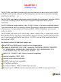
The PCCOM 8 port adapter provides eight asynchronous serial communication ports (RS232
or RS422), which link the computer and serial peripheral devices such as terminals, modems,
serial printers, plotters, ... etc.
The PCCOM 8 port adapter is particularly suited to facilitate the connection of terminals (VDUs)
in multi-user operating systems. Each board is supplied complete with many kinds of
connectors.
The PCCOM board may be installed in any PC/486, Pentium or hardware compatible systems.
To accommodate a variety of operating systems, three switch banks permit maximum flexibility
of configuration. You may select which interrupt (IRQ2 - IRQ7), I/O address, and interrupt
vector you desire.
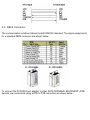
The PCCOM 8 port board can be used to plug in 8250, 16450, 16550, or 16650 chips, and the
PCCOM device driver can detect it automatically. There are two kinds of board can be choose,
one is normal speed card that its baud rate up to 115200, another is high speed card that its
baud rate up to 460K.
The features of the PCCOM 8 port adapter are:
Eight RS232 or RS422 ports for asynchronous communications.
Suitable for XENIX/UNIX (SCO, AT&T, Interactive, UNIXWARE), MS/DOS, WINDOWS/
NT, WINDOWS/95, WINDOWS/98, WINDOWS/2000, OS/2, MS/WINDOWS, PICK,
CONCURRENT DOS, QNX, PROLOGUE, MUMPS, ... etc.
IBM PC/AT, PC/386, PC/486, Pentium hardware compatibles.
Interrupt selectable. (IRQ2 - IRQ7)
Interrupt vector address selectable.
ARNET 8 multi-port card compatible.
I /O address selectable.
Auto-detect 16450 or 16550 or 16650 chips on board.
Baud rate up to 115200 for normal speed board and up to 460K for high speed board.
CHAPTER 2
UNPACKING INFORMATION
Check that your PCCOM package includes the following items:
PCCOM 8 port adapter.
User manual.
PCCOM98 software.
Connector.
Select one of follow items.
1. DB25 connector.
2. DB9 connector.
3.RJ-11 connector.
4. Expansion box with DB25 connector.
Warranty form.
CHAPTER 3
SYSTEM REQUIREMENTS
Before installing your PCCOM ISA bus 8 port adapter, make sure that :
The host computer is an IBM PC/AT, PC/386, PC/486, or Pentium compatibles.
The three switch blocks are correctly configured to coincide with the operating system you
are using.
The operating system you intend to use is capable of driving multiple serial ports.
CHAPTER 4
HARDWARE INSTALLATION
Your PCCOM 8 port adapter is designed to be inserted in any available slot in your PC/AT,
PC/386, PC/486, Pentium or compatibles. In order to gain access to the expansion slots, follow
the steps listed below:
1. Turn off all power to your computer and all peripheral devices before installing your
PCCOM 8 port adapter.
2. Remove the cover of the computer.
3. Insert the pre-configured PCCOM 8 port adapter into any available slot. Make sure the
adapter is firmly seated in the chosen slot.
4. Replace the cover of the computer.
5. Connect cables to eight RJ11, DB9, or D25 connectors as required.
CHAPTER 5
SWITCH SETTING
5.1 Introduction
The three switch blocks and three jumpers on the PCCOM 8 port adapter must be configured
correctly in accordance with the operating system you are using.
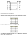
SW1 (Switch 1)
Determines the I/O address of the UARTs.
SW2 (Switch 2)
Selects which interrupt will be used in the range IRQ2 through IRQ7.
SW3 (Switch 3)
Selects the interrupt vector address and determines which port is active when an interrupt
occurs.
JP1 (Jumper 1)
Select master or slave board.
JP2 (Jumper 2)
Daisy chain jumper for installing more than one boards which use the common IRQ.
All addresses specified are in hexadecimal. The actual interrupt latch address is set to the
interrupt vector address set by switch 3 + 2H.
5.2 Selection of Switch Settings
It is important to refer to the user manual supplied with your operating system to determine the
correct configuration. Although we provide installation advice for various operating systems, it
is not possible to cover all systems in this user guide. Please contact your supplier if you have
any difficulties with configuration.
IMPORTANT : CARE MUST BE TAKEN IN SELECTING THE CONFIGURATION OF
SWITCHS TO ENSURE YOU DO NOT DUPLICATE SETTINGS OF OTHER EQUIPMENT
ALREADY INSTALLED IN YOUR COMPUTER. DUPLICATION OF SETTINGS WILL RESULT
IN A MALFUNCTION OF ONE OR BOTH DEVICES.
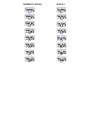
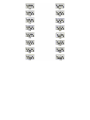
Please refer to the following settings for each switch block. If you are installing more than one
board, do not duplicate jumper settings for any parameter.
DECISION COMPUTER INTERNATIONAL CO .,LTD.
DECISION INTERNATIONAL CO.,LTD.
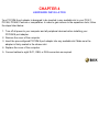
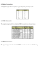
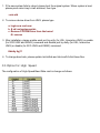
NOTE: The address selected must start on a multiple of 40H. A block of 40H contiguous I/O
locations will be used starting from the selected address.
The I/O port addresses corresponding to each port are shown in the following.
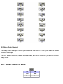
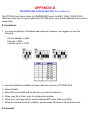
5.5 Daisy Chain Interrupt
The daisy chain interrupts function provides more than one PC COM 8 port board to use the
common interrupts.
The JP1 is used to identify master or slave board, and the JP2 (IN/OUT) is used to connect
daisy chain.
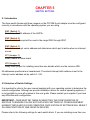
JP1: Select master or slave
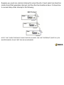
Suppose you used one common interrupt to serve 24 ports, it must select one board as
master board that generates interrupt, and the other two boards as slave. It shows how
to connect daisy chain interrupt in the following.
NOTE THAT, WHEN THE DAISY CHAIN FUNCTION IS USED, ONLY SET INTERRUPT (SWITCH 2) ON
MASTER BOARD, DO NOT SET IRQ ON SLAVE BOARD.
CHAPTER 6
RS232 & RS422 CABLING INFORMATION
6.1 RJ11 Connector
The communication interface follows the EIA RS232C standard. Each RS232 port has one RJ11 female connector for connection to a peripheral device. The board-mounted female RJ-11
pin identification is shown in the following:
The RJ-11 to DB25 expansion cable assignment is shown in the following:
To connect PCCOM 8 port adapter to other DATA TERMINAL EQUIPMENT (DTE)
devices, the developers recommend the following connection method.
6.2 DB25 Connector
The communication interface follows the EIA RS232C standard. The signal assignments
for a standard DB25 connector are shown below:
To connect the PCCOM 8 port adapter to other DATA TERMINAL EQUIPMENT (DTE)
devices, we recommend using a DTE to DTE connection as shown below :
6.3 Null Modem Connections: RS232
If the software supplier or operating system does not specify a particular cable configuration,
we recommend you use the following “null modem” cable when XON/XOFF is utilized.
If hardware handshaking is necessary, use the following cable:
Some serial devices have the buffer control signal on pin 19, in which case pin 6 on the host is
connected to pin 19 on the remote device.
6.4 Modem Connections
A straight through cable is required, e.g. pin 2 to pin 2, pin 3 to pin 3, etc.
6.5 DB9 Connector
The signal assignments for a standard DB9 connector are shown below:
6.6 RS422 Connector
The signal assignments for a standard DB25 connector are shown in the following.
To connect the RS422 to other DATA TERMINAL EQUIPMENT (DTE) devices, the developers
recommend using a DTE to DTE connection as shown below.
CHAPTER 7
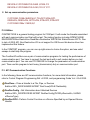
INTERRUPT LATCH ADDRESS
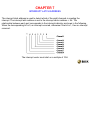
The interrupt latch address is used to detect which of the eight channels is creating the
interrupt. The interrupt latch address is set to the interrupt vector address + 2H. The
relationship between each port corresponds to the interrupt indicator as shown in the following.
When the corresponding bit is 0, an interrupt occurred, otherwise if the bit is 1, then no interrupt
occurred.
The interrupt vector must start on a multiple of 10H.
APPENDIX A
PC COM DIAGNOSTIC UNDER MS/DOS
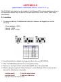
The PCCOMQC program provides a diagnostic routine to test your PCCOM 8 port serial
adapter under MS/DOS. It provides internal and external loopback tests. A loopback plug must
be connected to each port being tested, and you can select different signal's connection to test
communication signals from hardware configuration function.
To test your PCCOM 8 port adapter under MS/DOS, please type
A>PCCOMQC
(A>means system prompt )
* Then select "PCCOM 8 port Rs232" or "PCCOM 8 port RS422" item.
APPENDIX B
PC COM 98 DEVICE DRIVER FOR MS/DOS
B.1 PCCOM Software
The PCCOM V2.0 is a high performance, easy to use RS232/RS422 device driver for PC/XT,
PC/AT, PC/386, PC/486, Pentium or compatibles. Under MS/DOS environment, you can set up
your serial ports by PCCOM device driver, and these serial ports can be treated as COM1: and
COM2: devices. The setup procedure provides flexible functions to specify the configuration of
multi-serial card, that is, the hardware configurations of I/O port number, I/O port address,
interrupt and interrupt vector are user selectable.
After the device driver is installed, It takes over communication between CPU and multi-serial
cards such as four port card, eight port card, ... etc. For each I/O port, the service routine
handles a ring buffer to keep track of all I/O data. Moreover, the PCCOM software provides
library routines (C, PASCAL, BASIC, FoxPro) and DOS communication interface (DOS device
driver, BIOS call) for several access levels.
The PCCOM V2.0 is an upgrade version of PCCOM V1.0 software, if combines with PCCOM
V1.0 and SERIAL DRIVER utilities. Each serial port may be either 8250, 16450, 16550, or
16650 chip that was detected automatically.
For more details, please refer PCCOMV2 manual.
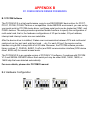
B.2 Hardware Configuration
B.3 Software Installation
When the board is installed, please install software drivers as follows:
STEP 1: Prepare PCCOM8.OPT file
The PCCOM8.OPT file contents are :
/B:2
/D:COM3
/A:[4:280,8,2C2,LO:(2k:9600:N-8-1:RTS+DTR:XON) * 8]
STEP 2: Prepare CONFIG.SYS file
Insert statement into CONFIG.SYS file
DEVICE = PCCOM.SYS @c:\pccom8.opt
If more than one PCCOM board is installed, Please refer to PCCOMV2 manual.
APPENDIX C
XENIX/UNIX CONFIGURATION
The distribution disk contains SCO, AT&T, UNIXWARE, and INTERACTIVE UNIX/XENIX
driver, it detects non-FIFO or FIFO chips automatically. Our drivers also provide transparent
printer features that let user to connect local printer from auxiliary port of terminal. The
hardware configuration and software installation procedures are shown is the bellows.
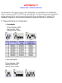
C.1 Suggested Hardware Configuration
1. First adapter
I/O port address: 280H
Interrupt level: IRQ4
Interrupt vector: 2C0H
2. Second Adapter
I/O port address: 240H
Interrupt level: IRQ3
Interrupt vector: 2D0H
C.2 Software Installation
The installation procedure for the device drivers is described as follows:
1. Login as a root user.
2. Insert distribution diskette (which contains device drivers) into floppy drive A:, then copy
the files from the distribution diskette to a temporary directory.
#cd /
# doscp d:dc.tz ./dc.tar.Z ["dosget" in Interactive UNIX]
# zcat dc.tar / tar xvfp 3. To install device drivers, please type:
#cd /usr/sys/pccom/dc
# ./install
4. Reboot the system. Now, your new UNIX system that includes device drivers is activated.
5. Enable each terminal by using the entty or enable command. For USL UNIX (AT&T,
UNIXWARE), Interactive UNIX
# entty ttyj11
# entty ttyj12
.
.
For SCO UNIX & XENIX by using enable command.
6. Connect each terminal to connector.
NOTE:
1. If the new system fails to reboot, please boot the original system. When system is boot,
please press return key to halt autoboot, then type
:unix.old
2. To remove device driver from UNIX, please type
a. login as a root user
b. # cd /usr/sys/pccom/dc
c. Remove PCCOM Driver from the kernel
#./ remove
3. After installation, please enable each port by entty (for USL, Interactive UNIX) or enable
(for SCO UNIX and XENIX) command and disable port by distty (for USL, Interactive
UNIX) or disable (for SCO UNIX and XENIX) command.
#distty ttyj11
4. To change baud rate, please update /etc/inittab and /etc/conf/cf.d/init.base files.
C.3 Option for High Speed
The configuration of High-Speed Baud Rate card is change as follows:
C.4 Transparent Printer
The default device names to Transparent Printer(TP) are /dev/lpXYY, that is, the prefix name is
changed from "tty" to "lp" but the other "XYY" is the same. e.g. under default device names, the
corresponding TTY line of /dev/lpj11 is /dev/ttyj11.
By multiplexing a serial line, there are two sorts of data channels for TTY data(by /dev/ttyXYY)
and TP data(by /dev/lpXYY). If the /dev/ttyj11 is used for a TTY, it has to be enabled before
you would like to print data through /dev/lpj11 to a printer that connected to the terminal that is
operated via /dev/ttyj11.
The channel for TP data that is uni-directional is used to transmit the data from a host to a
terminal only. The differentiates of TTY data and TP data in the same serial line is that TP data
are encapsulated within a couple of PRINT-ON and PRINT-OFF escape strings that are
recognized by connected terminals. The PRINT-ON and PRINT-OFF is defined by connected
terminals.
The scheme to multiplex a serial line for these two channels is based on time-division method.
The time slices for TTY or TP data are generated according to the entry procedure, polling, in
the PCCOM driver, which is periodically called by system clock. The period of system clocks is
different among various operating systems, e.g. most UNIXs is 100hz, but SCO Xenix is 50hz.
The interval reserved for TTY or TP channel in the same serial line is important to output TP
data to a low-speed printer through high-throughput line from PCCOM cards if there is no flow
control XON/XOFF to the serial line.
The lpx command is used to adjust the time interval for TTY or TP data and the TP protocol.
lpx [option] device name
option:
-t number: set interval for TTY
-l number: set interval for Transparent Printer
-n string: set esc string to turn on printer
-f string: set esc string to turn off printer
-T : get interval for TTY
-L : get interval for Transparent Printer
-N : get esc_string to turn on printer
-F : get esc_string to turn off printer
device_name : lpXYY
The range of interval reserved for TTY or TP channel is from 1 to maximum integer. The
default setting for any /dev/lpXYY is as follows:
Interval for TTY : 50
Interval for TP : 1
PRINT - ON escape : “\033[5i” (ESC[5i)
PRINT – OFF escape : “\033[4i” (ECS[4i)
1. The examples to invoke lpx
(1) Set 60 time slices reserved for /dev/ttyj11
# lpx -t 60 /dev/ttyj11
(2) Set 2 time slices reserved for /dev/lpj11
# lpx 12 /dev/lpj11
(3) Get the time slices reserved for /dev/lpj11
# lpx L /dev/lpj11
(4) Set PRINT-ON string for /dev/lpj11
# lpx n \033[51 /dev/lpj11
(5) Get PRINT-OFF string for /dev/lpj11
# lpx F /dev/lpj11 \033[4i
APPENDIX D
MS-WINDOWS CONFIGURATION for version 3.x
The PCCOM 8 port device driver for MS/WINDOWS works for 8250, 16450, 16550 (FIFO),
16650 etc. User can set up any address to PCCOM 8 port card, and the address must be set to
consecutive.
D.1 Installation
1. You may set arbitrary I/O address and interrupts. However, we suggest you use the
following:
I/O port address = 280H
Interrupt = IRQ5
Interrupt vector = 2C0H
2. Insert the distribution diskette to floppy disk drive, then run PCCOMW.EXE.
3. Select [Install].
4. Select the source path and the directory you want to install in it.
5. When copy file is finish, enter to configuration window.
6. Select your card type and the correct address/ IRQ value, then press [OK].
7. When the window presents 'complete', please restart Windows to let the driver work.
D.2 Uninstall
1. Enter Windows to run PCCOMW.EXE by click on PCCOM icon.
2. Select [Uninstall], and confirm that sure to uninstall.
3. When the window shows 'Uninstall complete'', restart Windows to let old driver work.
D.3 Utilities
1. Programming Manual
Since window manager can recognize only COM1 to COM9, however, to install PCCOM 8 port
card, it may occupy COM3 to COM10. In the distribution diskette, we provide DLL library and
include file, all functions are similar to USER.EXE functions.
Files: COMMX.DLL
COMMX.LIB
COMMX.H
COMMX.DOC
(Dynamic linked library for aux COMs)
(Static library for aux COMs API)
(The include file for C/C++)
(Document)
PCCOM library functions are similar to API Comm function
API functions are ???.COMM???()
PCCOM functions are ???.COMMX???()
For example, OpenComm() become OpenCommX() , parameters are the same.
Following are the functions used with communications devices.
int FAR PASCAL _export BuildCommXDCB(LPCSTR, DCB FAR*);
int FAR PASCAL _export OpenCommX(LPSTR, UINT, UINT);
int FAR PASCAL _export CloseCommX(int);
int FAR PASCAL _export ReadCommX(int, LPSTR , int);
int FAR PASCAL _export WriteCommX(int,LPSTR , int);
int FAR PASCAL _export UngetCommXChar(int, char);
int FAR PASCAL _export FlushCommX(int, int);
int FAR PASCAL _export TransmitCommXChar(int, char);
int FAR PASCAL _export SetCommXState(const DCB FAR*);
int FAR PASCAL _export GetCommXState(int, DCB FAR*);
int FAR PASCAL _export GetCommXError(int, COMSTAT FAR* );
int FAR PASCAL _export SetCommXBreak(int);
int FAR PASCAL _export ClearCommXBreak(int);
UINT FAR* FAR PASCAL _export SetCommXEventMask(int, UINT);
UINT FAR PASCAL _export GetCommXEventMask(int, int);
LONG FAR PASCAL _export EscapeCommXFunction(int, int);
BOOL FAR PASCAL _export EnableCommXNotification(int, HWND, int, int);
2. Under standard WINDOW environment, to use "TERMINAL" and "CONTROL PANEL",
only COM1 to COM4 can be used. If you need use COMx (more than COM4) with
TERMINAL.EXE, please modify WIN.INI before enter to WINDOW. For example, to use
COM6 with TERMINAL.EXE, please find
[TERMINAL]
port=COMx
in WIN.INI, then modify port=COMx to port=COM6.
3. No modification are necessary for applications using up to COM9, and the printers ,
modems may be connected up to COM9.
4. SPECIAL NOTE : When you set 115200 baud( only with FIFOs ), please set 0xFF20 (or
CBR_56000+1 ) to certain functions.
D.4 Testing
1. Open two terminal applications under Windows.
2. Open COM port for each terminal, and have the same configuration(baud, stop bit,
protocol...) e.g.
Open COM3 to one terminal
(9600 baud, 1 stop bit, 8 data bit)
Open COM4 to another terminal (9600 baud, 1 stop bit, 8 data bit)
3. Use 'NULL MODEM' method to connect the two ports.
4. Try to transmit and receive data between the two terminal windows.
APPENDIX E
WINDOWS 95 CONFIGURATION
The PCCOM 8 port adapter can be installed in the Windows 95 by using serial device driver in
the distribution diskette, and the device driver will detect 8250, 16450, 16550, 16650 chips
automatically.
E.1 Installation
1. You may set arbitrary I/O address and interrupts. However, we suggest you use the
following:
I/O port address = 280 H
Interrupt = IRQ5
Interrupt vector = 2C0H
2. Insert the distribution diskette into floppy disk drive, then run SETUP.EXE.
3. Click "PCCOM98 Setup Panel" to run configuration setup.
4. Select your card type and the correct address/IRQ value, then press [OK[.
5. When a dialog box presents "Setup Complete", restart Windows 95 to let driver work.
If you need install more than one card, please run "PCCOM98 Setup Panel" again. Do not set
the same address and interrupt.
E.2 Remove Ports
1. Enter Windows 95.
2. Enter [Control Panel] \ [System] \ [Device Manager] \ [Port].
3. Select the port that you want to remove, then press [Remove] to remove it.
E.3 Uninstall
1. Remove the file group and icons that created by InstallShield.
2. Enter [Control Panel] \ [Add/Remove Programs], select the"PCCOM98 Setup Panel" and
remove it
APPENDIX F
OS/2 CONFIGURATION
Under OS/2 2.x and OS/2 Warp operating system, the PCCOM device driver provides total 96
ports and baud rate up to 115200. PCCOM also supports device driver for high speed card,
and the baud rate can be up to 460800. The device driver works for 8250, 16450, 16550
(FIFO), 16650 etc. User can set up any address to PCCOM 8 port card, and the address must
be set to consecutive.
F.1 Installation
The installation procedures are shown in the following.
1. Add command into CONFIG.SYS file then reboot.
DEVICE=C:\PCCOM8.SYS/Axxx,www /Iyy/Czz /4
xxx
www
yy
zz
4
The first I/O port address
The interrupt vector address
IRQ2 to IRQ7
Assign the first port name (1 to 92)
High speed card used only
if "/C" is not use, the first port is COM3.
If option /C1 or /C2 is use, the port COM1 or COM2 is a logical port but not compatible to
COM1 or COM2 on a PC machine.
I/O Vector address value has to shift 2 from the original value (ex. 2C0H is replaced by
2C2H).
2. To set up communication parameters, please use the MODE.COM command from OS/2,
or use PCCOM.EXE command. We highly recommend to use PCCOM.EXE command,
because MODE.COM can be used only for COM1 to COM9 and for maximum baud rate to
57600.
The PCCOM.EXE can be used to set COM1 to COM96. The syntax of PCCOM.EXE is the
same as MODE.COM.
For example :
1. Set two cards from COM3 to COM10 and COM11 to COM18.
DEVICE=C:\PCCOM8.SYS /A240 ,2C2/I5 /C3
DEVICE=C:\PCCOM8.SYS /A1A0,1C2 /I7 /C11
2. Set up communication parameters.
C:\PCCOM COMx:38400,N,8,1,TO=OFF,XON=OFF,
IDSR=ON, ODSR=ON, OCTS=ON, RTS=OFF,DTR=OFF
C:\PCCOM COMx:115200,N,1
F.2 Utilities
COMTEST.EXE is a general testing program for COM port. It will create the threads associated
with each communication port that will be test. The testing function includes OPEN/CLOSE/
READ/WRITE/Non-Destructive Read/Non-Destructive WRITE/Get Status/Device IOCTL. Due
to lack of OS/2 API, Non-Destructive I/O is not support for OS/2 even this device driver has
implemented this feature.
In the COMTEST program, you can use up-right arrow to choice the option, and use enter/
escape to start/stop the program.
The ComSent/ComRecv are a pair of communication programs for testing the performance of
communication port. You have to connect the test ports with a null modem before you test
communication port. You can use PCCOM.EXE to change the parameters of communication
port. Then use this program to test heavy (transmission) duty on communication port. F.3 API Communication Functions
In the following, there are API communication functions, for more detail information, please
refer to Control Program Programming Ref. of OS/2, and programming Guide Vol. I-III of OS/2.
DosClose - Close a Handle to a File, Pipe, or Devices
#define INCL_DOSFILEMGR APIRET DosClose(HFILE FileHandle);
DosDevConfig - Get Information about Attached Devices
#define INCL_DOSPROCESS APIRET DosDevConfig(PVOID pDeviceInfo, ULONG
ulDeviceType);
DosDevIOCtl - Perform Control Function on a Device Specified by an Opened Device
Handle
#define INCL_DOSPROCESS APIRET DosDevIOCtl(HFILE DevHandle, ULONG
ulCategory, ULONG ulFunction, PVOID pParmList, ULONG ulParmLengthMax, PULONG
pParmLengthInOut, PVOID pDataArea, ULONG ulDataLengthMax, PULONG
pDataLengthInOut);
DosOpen - Open a File
#define INCL_DOSFILEMGR APIRET DosOpen(PSZ pszFileName, PHFILE
ppFileHandle, PULONG pActionTaken, ULONG ulFileSize, ULONG ulFileAttribute,
ULONG ulOpenFlag, ULONG ulOpenMode, PEAOP2 ppEABuf);
DosRead - Read from a File, Pipe, or Device to a Buffer
#define INCL_DOSFILEMGR APIRET DosRead(HFILE FileHandle, PVOID pBufferAre,
ULONG ulBufferLength, PULONG pByteRead);
DosWrite - Write to a File from a Buffer
#define INCL_DOSFILEMGR APIRET DosWrite(HFILE FileHandle, PVOID pBufferArea,
ULONG ulBufferLength, PULONG pByteWritte);
APPENDIX G
WINDOWS/NT CONFIGURATION for version 3.51 up
The PCCOM 8 port adapter can be installed in the Windows NT by using serial device driver in
the distribution diskette, and the device driver will detect 8250, 16450, 16550, 16650 chips
automatically.
G.1 Installation
1. You may set arbitrary I/O address and interrupts. However, we suggest you use the
following:
I/O port address = 280 H
Interrupt = IRQ5
Interrupt vector = 2C0H
2. Insert the distribution diskette into floppy disk drive. then run SETUP.EXE.
3. Click "PCCOM98 Setup Panel" to run configuration setup.
4. Select your card type and the correct address/IRQ value, then press [OK].
5. When a dialog box presents "Setup Complete", restart Windows NT to let driver work or
execute the following two commands :
net stop serial
// stop the origin driver
net start serial
// start our new driver
then our driver will start to work.
6. The COM1 to COM9 can be directly referenced just like a filename from program and from
the command line. However, COM10 and above must be referenced with the following
syntax :
\\.\com10
Because the command line mode doesn't recognize ports above COM9.
7. Don't overlap port address and interrupt vector address, otherwise, it may conflict with
UART chips.
8. If you need install more than one card, please run "PCCOM98 Setup Panel" again. Do not
set the same address and interrupt.
G.2 Remove Ports
1. Enter Windows NT.
2. Enter [Control Panel] \ [Ports].
3. Select the port to delete.
G.3 Uninstall
1. Remove the file group and icons that created by InstallShield.
2. Enter [Control Panel] \ [Add/Remove Program], select the "PCCOM98 Setup Panel" and
remove it.
APPENDIX H
CONCURRENT DOS CONFIGURATION
MULTI - USER DOS CONFIGURATION
Set I/O port address to 280, interrupt to IRQ3 and interrupt vector to 270H. To install device
drivers, please run the SETUP program, then follow the menu instructions to set up I/O port
address, communication parameters (such as: baud rate, parity, data bits, ... etc.), and
handshaking. The hardware configuration is shown below:
For multi-user DOS (Dr. DOS) configuration, set I/O port address to 280H, and interrupt vector
to 270H. Any interrupt (IRQ3 to IRQ7) is used.
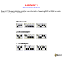
APPENDIX I
PICK CONFIGURATION
Refer to PICK user installation guide for more information. If selecting IRQ3 or IRQ4 be sure to
disable existing COM1 or COM2 ports.
APPENDIX J
LINUX CONFIGURATION
The PCCOM 8 port adapter can be installed in the Linux by using serial device driver
supported by Linux, and the device driver will detect 8250, 16450, 16550, 16650 chips
automatically. For more details, please refer to 'setserial' man-pages.
I/O port address = 100H
Interrupt = IRQ12
Chip type = 16550A
Please add the following lines to /etc/rc.d/rc.serial or rc.local file.
SETSERIAL="/bin/setserial -b"
${SETSERIAL} /dev/cua16 uart 16550 port 0x100 irq 12
${SETSERIAL} /dev/cua17 uart 16550 port 0x108 irq 12
${SETSERIAL} /dev/cua18 uart 16550 port 0x110 irq 12
${SETSERIAL} /dev/cua19 uart 16550 port 0x118 irq 12
${SETSERIAL} /dev/cua20 uart 16550 port 0x120 irq 12
${SETSERIAL} /dev/cua21 uart 16550 port 0x128 irq 12
${SETSERIAL} /dev/cua22 uart 16550 port 0x130 irq 12
${SETSERIAL} /dev/cua23 uart 16550 port 0x138 irq 12
APPENDIX K
WARRANTY INFORMATION
K.1 Copyright
Copyright 1997, 1998, DECISION COMPUTER INTERNATIONAL CO., LTD. All rights
reserved. No part of PCCOM software and manual may be reproduced, transmitted,
transcribed, or translated into any language or computer language, in any form or by any
means, electronic, mechanical, magnetic, optical, chemical, manual, or otherwise, without the
prior written permission of DECISION COMPUTER INTERNATIONAL CO., LTD.
Each piece of PCCOM package permits user to use PCCOM only on a single computer, a
registered user may use the program on a different computer, but may not use the program on
more than one computer at the same time.
Corporate licensing agreements allow duplication and distribution of specific number of copies
within the licensed institution. Duplication of multiple copies is not allowed except through
execution of a licensing agreement. Welcome call for details.
K.2 Warranty Information
DECISION warrants that for a period of one year from the date of purchase (unless otherwise
specified in the warranty card) that the goods supplied will perform according to the
specifications defined in the user manual. Furthermore that the PCCOM product will be
supplied free from defects in materials and workmanship and be fully functional under normal
usage.
In the event of the failure of a PCCOM product within the specified warranty period, DECISION
will, at its option, replace or repair the item at no additional charge. This limited warranty does
not cover damage resulting from incorrect use, electrical interference, accident, or modification
of the product.
All goods returned for warranty repair must have the serial number intact. Goods without serial
numbers attached will not be covered by the warranty.
Transportation costs for goods returned must be paid by the purchaser. Repaired goods will be
dispatched at the expense of PCCOM.
To ensure that your PCCOM product is covered by the warranty provisions, it is necessary that
you return the Warranty card.
Under this Limited Warranty, DECISION's obligations will be limited to repair or replacement
only, of goods found to be defective as specified above during the warranty period. DECISION
is not liable to the purchaser for any damages or losses of any kind, through the use of, or
inability to use, the PCCOM product.
DECISION reserves the right to determine what constitutes warranty repair or replacement.
Return Authorization: It is necessary that any returned goods are clearly marked with an RA
number that has been issued by DECISION. Goods returned without this authorization will not
be attended to.
WCSC