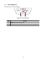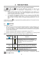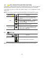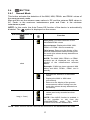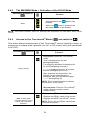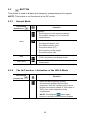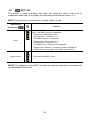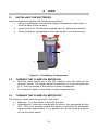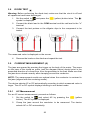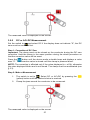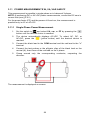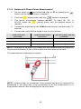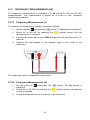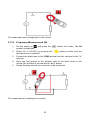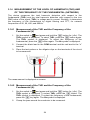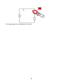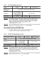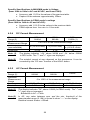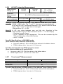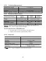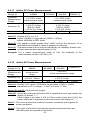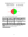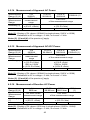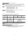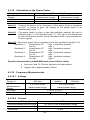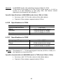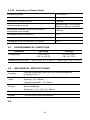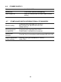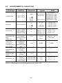
1
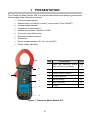
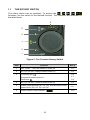
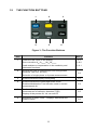
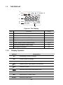
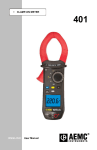
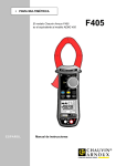
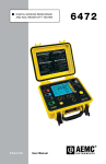
POWER CLAMP-ON METER 405 ENG L ISH User Manual 2 CONTENTS RECEIVING YOUR SHIPMENT ........................................................................... 8 ORDERING INFORMATION ................................................................................ 8 1 PRESENTATION .......................................................................................... 9 1.1 THE ROTARY SWITCH............................................................................... 10 1.2 THE FUNCTION BUTTONS ........................................................................ 11 1.3 THE DISPLAY .............................................................................................. 12 1.3.1 Display Symbols ........................................................................... 12 1.3.2 Measurement Capacity Exceeded (OL) ........................................ 13 1.4 THE TERMINALS ........................................................................................ 14 2 THE BUTTONS ........................................................................................... 15 (YELLOW) BUTTON (SECOND FUNCTION) ............................................ 16 BUTTON ............................................................................................. 16 BUTTON ............................................................................................. 17 Normal Mode ................................................................................ 17 The MAX/MIN Mode + Activation of the HOLD Mode ................... 18 2.4.3 2.5 2.5.1 2.5.2 Access to the True Inrush® Mode ( set to ) ................... 18 BUTTON ............................................................................................. 19 Normal Mode ................................................................................ 19 The Hz Function + Activation of the HOLD Mode ......................... 19 2.6 3 BUTTON............................................................................................... 15 2.1 2.2 2.3 2.4 2.4.1 2.4.2 BUTTON ........................................................................................... 20 USE ............................................................................................................. 21 3.1 INSTALLING THE BATTERIES................................................................... 21 3.2 TURNING THE CLAMP-ON METER ON .................................................... 21 3.3 TURNING THE CLAMP-ON METER OFF .................................................. 21 3.4 CONFIGURATION....................................................................................... 22 3.4.1 Configuring the Maximum Resistance for Continuity .................... 22 3.4.2 Auto Power OFF ........................................................................... 22 3.4.3 Configuring the Threshold for True InRush® Measurement .......... 22 3.4.4 Default Configuration .................................................................... 23 3.5 VOLTAGE MEASUREMENT (V) ................................................................. 23 3.6 CONTINUITY TEST ............................................................................... 24 3.6.1 Lead Resistance Compensation ................................................... 25 3.7 RESISTANCE MEASUREMENT Ω............................................................. 25 3.8 DIODE TEST ......................................................................................... 26 3.9 CURRENT MEASUREMENT (A) ................................................................ 26 3.9.1 AC Measurement .......................................................................... 26 3.9.2 DC or AC+DC Measurement ....................................................... 27 3 STARTING CURRENT OR OVERCURRENT (True InRush®) MEASUREMENT ......................................................................................... 28 3.11 POWER MEASUREMENTS W, VA, VAR AND PF ....................................... 29 3.11.1 Single-Phase Power Measurement ............................................... 29 3.11.2 Balanced 3-Phase Power Measurement ....................................... 30 ............................................................... 31 3.12 PHASE ROTATION MODE 3.13 FREQUENCY MEASUREMENT (HZ) ......................................................... 32 3.13.1 Frequency Measurement (V) ........................................................ 32 3.13.2 Frequency Measurement (A) ........................................................ 32 3.13.3 Frequency Measurement (W) ....................................................... 33 3.14 MEASUREMENT OF THE LEVEL OF HARMONICS (THD) AND THE FREQUENCY OF THE FUNDAMENTAL (NETWORK) ..................... 34 3.14.1 Measurement of THD and Frequency of the Fundamental (V) ..... 34 3.14.2 Measurement of THD and Frequency of the Fundamental (A) ..... 34 3.10 4 SPECIFICATIONS ...................................................................................... 36 4.1 REFERENCE CONDITIONS ....................................................................... 36 4.2 SPECIFICATIONS UNDER THE REFERENCE CONDITIONS ................. 36 4.2.1 DC Voltage Measurement ............................................................. 36 4.2.2 AC Voltage Measurement ............................................................. 37 4.2.3 AC+DC Voltage Measurement ...................................................... 37 4.2.4 DC Current Measurement ............................................................. 38 4.2.5 AC Current Measurement ............................................................. 38 4.2.6 AC+DC Intensity Measurement .................................................... 39 4.2.7 True Inrush® Measurement ........................................................... 39 4.2.8 Continuity Measurement ............................................................... 40 4.2.9 Resistance Measurement ............................................................. 40 4.2.10 Diode test ...................................................................................... 40 4.2.11 Active DC Power Measurements .................................................. 41 4.2.12 Active AC Power Measurements .................................................. 41 4.2.13 Active AC+DC Power Measurements ........................................... 42 4.2.14 Measurement of Apparent AC Power ........................................... 43 4.2.15 Measurement of Apparent AC+DC Power .................................... 43 4.2.16 Measurement of Reactive AC Power ............................................ 43 4.2.17 Measurement of reactive AC+DC power ....................................... 44 4.2.18 Calculation of the Power Factor .................................................... 45 4.2.19 Frequency Measurements ............................................................ 45 4.2.20 Specifications in THDr .................................................................. 46 4.2.21 Specifications in THDf ................................................................... 46 4.2.22 Indication of order of the phases ................................................... 47 4.3 ENVIRONMENTAL CONDITIONS.............................................................. 47 4.4 MECHANICAL SPECIFICATIONS .............................................................. 47 4.5 POWER SUPPLY ........................................................................................ 48 4.6 COMPLIANCE WITH INTERNATIONAL STANDARDS ............................. 48 4.7 ENVIRONMENTAL VARIATIONS............................................................... 49 4 5 MAINTENANCE .......................................................................................... 50 5.1 5.2 5.3 WARNING .................................................................................................... 50 CLEANING ................................................................................................... 50 REPLACEMENT OF THE BATTERIES ...................................................... 50 6 REPAIR AND CALIBRATION .................................................................... 51 7 TECHNICAL AND SALES ASSISTANCE .................................................. 51 8 LIMITED WARRANTY ................................................................................ 52 9 WARRANTY REPAIRS .............................................................................. 52 5 Thank you for purchasing a Model 405 Clamp-on Meter. For best results from your instrument and for your safety, read the enclosed operating instructions carefully and comply with the precautions for use. These products must be only used by qualified and trained users. Meanings of the symbols used on the device CAUTION - Risk of Danger! Indicates a WARNING and that the operator must refer to the user manual for instructions before operating the instrument in all cases where this symbol is marked. Risk of electric shock. The voltage at the parts marked with this symbol may be dangerous. Refers to a type A current sensor. This symbol signifies that application around and removal from HAZARDOUS LIVE conductors is permitted. 1.5 V battery The CE marking indicates compliance with European directives Double insulation or reinforced insulation In the European Union, this product is subject to a separate collection system for recycling electrical and electronic components In accordance with directive WEEE 2002/96/EC AC – Alternating current AC and DC – Alternating and direct current Ground/Earth 6 PRECAUTIONS FOR USE This device complies with safety standards IEC-61010-1 and 61010-2-032 for voltages of 1000V in category IV at an altitude of less than 2000m, indoors, with a degree of pollution not exceeding 2. These safety instructions are intended to ensure the safety of persons and proper operation of the device. The operator and/or the responsible authority must carefully read and clearly understand the various precautions to be taken in use. If this instrument is used other than as specified, the protection it provides may be compromised, thereby endangering you. Do not use the instrument in an explosive atmosphere or in the presence of flammable gases or fumes. Do not use the instrument on networks of which the voltage or category exceeds those mentioned. Do not exceed the rated maximum voltages and currents between terminals or with respect to earth. Do not use the instrument if it appears to be damaged, incomplete, or not properly closed. Before each use, check the condition of the insulation on the leads, housing, and accessories. Any element of which the insulation is deteriorated (even partially) must be set aside for repair or scrapped. Use leads and accessories rated for voltages and categories at least equal to those of the instrument. If not, an accessory of a lower category lowers the category of the combined Clamp + accessory to that of the accessory. Observe the environmental conditions of use. Replace the batteries as soon as the symbol appears on the display of the unit. Disconnect all leads before opening the battery compartment cover. Use personal protective equipment when conditions require. As a safety measure, and to avoid repeated overloads on the inputs of the device, configuration operations should only be performed when the device is disconnected from all dangerous voltages. Do not modify the instrument and only use factory replacement parts. Repairs and adjustments must be done by approved qualified personnel. Keep your hands away from the unused terminals of the instrument. When handling the test probes, alligator clips, and clamp ammeters, keep your fingers behind the physical guard. 7 MEASUREMENT CATEGORIES Definitions of the measurement categories: CAT II: Circuits directly connected to the low-voltage installation. Example: power supply to household electrical appliances and portable tools. CAT III: Power supply circuits in the installation of the building. Example: distribution panel, circuit-breakers, fixed industrial machines or devices. CAT IV: Circuits supplying the low-voltage installation of the building. Example: power lines, meters, and protection devices. RECEIVING YOUR SHIPMENT Upon receiving your shipment, make sure that the contents are consistent with the packing list. Notify your distributor of any missing items. If the equipment appears to be damaged, file a claim immediately with the carrier and notify your distributor at once, giving a detailed description of any damage. Save the damaged packing container to substantiate your claim. ORDERING INFORMATION Clamp-on Meter Model 405 .......................................................... Cat. #2139.50 Includes set of 2 color-coded silicone insulated test leads, test probes and alligator clips, soft carrying case, 4x1.5V AA batteries and user manual. Replacement Parts: Soft Carrying Case ........................................................................................... Cat. #2139.72 Set of 2 Color-coded Silicone Test Leads, Test Probes & Alligator Clips ........ Cat. #2152.05 8 1 PRESENTATION The Clamp-on Meter Model 405 is a professional electrical measuring instrument that combines the following functions: Current measurement ® Measurement of InRush current / overcurrent (True InRush ) Voltage measurement Frequency measurement Measures harmonic distortion (THD) Continuity test with buzzer Resistance measurement Diode test Power measurements (W, VA, var and PF) Phase order indication 1 Item 3 4 Jaws with centering marks 3.5 to (see connection principles) 3.12 2 Physical Guard 3 Rotary Function Switch 4 Function Buttons 5 Backlit Display 1.3 6 Input Terminals 1.4 7 Trigger 5 6 Figure 1: Clamp-on Meter Model 405 9 See § 1 2 7 Designation 1.1 2 - 1.1 THE ROTARY SWITCH The rotary switch has six positions. To access the , , , , functions, set the switch to the desired function. The functions are described in the table below. 6 5 4 3 2 1 Figure 2: The Function Rotary Switch Item Function See § 1 OFF mode – Turns the clamp-on meter off 3.3 2 AC, DC, AC+DC voltage measurement (V) 3.5 3 Continuity test 3.6 Resistance measurement Ω 3.7 Diode test 3.8 4 AC, DC, AC+DC current measurement (A) 3.9 5 Power measurements (W, var, VA) and calculation of the power factor (PF) AC, DC, AC+DC 3.11 6 Phase rotation order indicator - 3.12 10 1.2 THE FUNCTION BUTTONS 1 2 4 5 3 6 Figure 3: The Function Buttons Item 1 2 Function Holds the last value on the display See § 2.1 Zero correction ADC/AAC+DC/WDC/WAC+DC 3.9.2 Lead resistance compensation in the continuity and ohmmeter functions 3.6.1 Selects the type of measurement and configuration functions (AC, DC, AC+DC) 2.2 Selection of single-phase or 3-phase measurement 3 Enables/disables display backlighting 4 Enables/disables the MAX/MIN/PEAK mode ® Enables/disables the True InRush mode in current measurement (A) 5 Performs Frequency measurements (Hz) and selects measurement of harmonic distortion (THD) 2.3 2.4 2.5 Display of the powers W, VA, var and PF 6 Activation of ΔREL mode – Displays differential and relative values 11 2.6 1.3 THE DISPLAY 7 6 1 2 3 4 5 Figure 4: The Display Item 1.3.1 Function See § 1 Mode selection display 2 2 Display of the measurement value and unit 3 Display of the MAX/MIN/PEAK modes 2.4 4 Type of measurement (AC or DC) 2.2 5 Total 3-phase power measurements 6 Selected resistance mode display 1.1 7 Low battery indication 5.3 Display Symbols Symbol Designation AC Alternating current or voltage DC Direct current or voltage AC+DC Alternating and direct current or voltage ∆REL Relative value, with respect to a reference ∆Ref Reference value Storage of the values and display hold Max Maximum DC or RMS value Min Minimum DC or RMS value PEAK+ Maximum peak value 12 3.5 to 3.12 3.11.2 PEAK- Minimum peak value Balanced total 3-phase power measurement V Volt Hz Hertz W Watt A Ampere % Percentage Ω Ohm m Milli- prefix k Kilo- prefix var Reactive power VA Apparent power PF Power factor THDf Total harmonic distortion with respect to the fundamental THDr Total harmonic distortion with respect to the true RMS value of the signal. Phase order indication Lead resistance compensation Continuity test Diode test Auto Power Off disabled Low battery indicator The display of “rdy”, for “ready”, indicates that the device is ready (Phase Order Indication function). 1.3.2 Measurement Capacity Exceeded (OL) The OL (Over Load) symbol is displayed when the display capacity is exceeded. 13 1.4 THE TERMINALS The terminals are used as follows: 1 2 Figure 5: The Terminals Item Function 1 COM (black) Input Terminal Jack 2 + Positive (red) Input Terminal Jack 14 2 THE BUTTONS The buttons respond differently to short, long, and sustained presses. The , and keys provide additional functions as well as the detection and acquisition of parameters complementary to the basic measurements. • Each of these buttons can be used independently of the others or in conjunction with each other. This makes navigation simple and intuitive when reviewing measurement results. • It is possible, for example, to either look up in sequence the MAX, MIN, etc. values of the RMS voltage alone, or look up in sequence all of the MAX (or MIN, or PEAK) values of all power measurements (W, VA, var, etc.). In this section, the icon represents the possible positions of the switch for the button’s functionality. BUTTON 2.1 This button is used to: Store and look up the last values acquired specific to each function (V, A, Ω, W) according to the specific modes previously activated (MAX/MIN). The present display is then maintained while the detection and acquisition of new values continues. Perform automatic lead resistance compensation (see § 3.6.1). Perform automatic zero correction in ADC/AC+DC and WDC/AC+DC (see § 3.9.2). NOTE: This button is invalid for the Phase Order Indication function. Successive presses on Function First press: Holds the last value displayed Second press: Returns to normal display mode (the value of each new measurement is displayed) long (> 2 sec) ADC AAC+DC WDC WAC+DC long (> 2 sec) See § 2.4.2 and § 2.5.2 for the and Performs automatic zero correction (see 3.9.2) NOTE: This mode operates if the MAX/MIN or HOLD modes (short press) are first de activated Performs automatic lead resistance compensation (see 3.6.1) button functionality in combination with the buttons. 15 2.2 (YELLOW) BUTTON (SECOND FUNCTION) This button is used to select the type of measurement (AC, DC, AC+DC) and the second functions marked in yellow next to the relevant positions of the switch. It can also be used to modify the default values in the configuration mode (see § 3.4). NOTE: This button is invalid in the MAX/MIN/PEAK, HOLD and ΔREL modes. Successive presses on Function - Selects AC, DC or AC+DC. Depending on your choice, the screen displays AC, DC or AC+DC short - Cycles through the continuity , Ω and diode test modes and returns to the continuity test - Resets the measurement process for the phase order indication function long (>2 sec) 2.3 - Displays the total 3-phase power of a balanced system ( is displayed). Press again to return to the display of the singlephase power ( is off) BUTTON Successive Function presses on - Enables/disables display backlighting NOTE: The backlighting is automatically disabled at the end of 2 minutes. 16 2.4 BUTTON 2.4.1 Normal Mode This button activates the detection of the MAX, MIN, PEAK+ and PEAK- values of the measurements made. Max and Min are the extreme mean values in DC and the extreme RMS values in AC. Peak+ is the maximum instantaneous peak and Peak- is the minimum instantaneous peak. NOTE: In this mode, the Auto Power Off function of the device is automatically disabled. The symbol is displayed on the screen. Successive presses on Function First press: Activates detection of the MAX/MIN/PEAK values Second press: Displays the MAX, MIN, PEAK+ or PEAK- value successively Third press: Returns to the display of the present measurement without exiting from the mode (the values already detected are not erased) short NOTE: The MAX, MIN, PEAK+ or PEAKsymbols are all displayed, but only the symbol of the measurement selected blinks. Example: If MIN has been selected, MIN blinks and MAX, PEAK+, PEAK- are lit steadily. - Activates the detection of MAX/MIN values - Displays the MAX or MIN value successively - Returns to the display of the present measurement without exiting from the mode (the values already detected are not erased). - Exits the MAX/MIN/PEAK mode. The values previously recorded are then erased. long (> 2 sec) NOTE: If the HOLD function is enabled, it is not possible to exit from the MAX/MIN/PEAK mode. The HOLD function must first be disabled first. NOTE : ΔREL function can be used with the functions of the MAX/MIN/PEAK mode. 17 2.4.2 The MAX/MIN Mode + Activation of the HOLD Mode Successive presses on Function - Displays the MAX/MIN/PEAK values detected before the button was pressed. - When the button is pressed, the last value is held on the display. short NOTE: The HOLD function does not interrupt the acquisition of new MAX, MIN, PEAK values 2.4.3 Access to the True Inrush® Mode ( set switch to ) This button allows measurement of the True Inrush® current (starting current, or overcurrent in steady-state operation) for AC or DC current only (not operational in AC+DC). Successive presses on Function - First press: Enters the True InRush mode ® - "Inrh" is displayed for 3s (the backlighting blinks) - The triggering threshold is displayed for 5s (the backlighting is steady) long (>2 sec) - "------" is displayed and the "A" symbol flashes (backlighting turns off) - After detection and acquisition, the InRush current measurement is displayed, after the calculations stage "------" (backlighting off) NOTE: The A symbol flashes to indicate "surveillance" of the signal. - Second press: Exits the True InRush mode (returns to simple current measurement). short (<2 sec) ® - Displays the PEAK+ value of the current - Displays the PEAK- value of the current Note: A short press is functional only if a True InRush value has been detected. ® - Displays the RMS True InRush current NOTE: The A, AC and PEAK values flash during this sequence. 18 2.5 BUTTON This button is used to display the frequency measurements of a signal. NOTE: This button is not functional in the DC mode. 2.5.1 Normal Mode Successive presses on Function Displays: - The frequency of the signal measured - The present voltage (V) or current (A) measurement short Displays: - The apparent power (VA) - The reactive power (var) - The power factor (PF) - The frequency of the signal - The active power (W) 2.5.2 long - Enters or exits from the level of harmonics (THD) calculation and display mode then short - Selects THDf, THDr or the frequency of the fundamental The Hz Function + Activation of the HOLD Mode Successive Function presses on - Holds the last frequency reading - Successively displays the last held frequency, then the voltage or the current - Displays the stored values of THDf, then of THDr, then of the frequency of the fundamental - NOTE: Pressing the button again returns to realtime measurement updates. 19 2.6 BUTTON This button is used to display and store the reference value in the unit of magnitude measured, or to display the differential and relative values, in %. NOTE: This button is not functional in phase rotation mode. Successive Function presses on Enters the ΔREL mode, to store, then display the reference value. The ΔRef symbol is displayed. short - Displays the differential value: (current value – reference (∆)) The ΔREL symbol is displayed. - Displays the relative value in % (current value – reference (∆)) The ΔREL and % symbols are displayed. - Displays the reference. The ΔRef symbol is displayed - Displays the current value. The ΔRef symbol blinks. long (>2 sec) - Exits from the ΔREL mode NOTE: The “Relative mode ΔREL” function can also be used with the functions of the MAX/MIN/PEAK mode. 20 3 USE 3.1 INSTALLING THE BATTERIES Insert the batteries supplied with the device as follows: 1. Using a screwdriver, unscrew the battery compartment cover (item 1) from the back of the housing. 2. Insert the 4x1.5V AA batteries supplied (item 2), observing polarities. 3. Close the battery compartment cover and screw it onto the housing. 2 1 Figure 6 : The Battery Compartment 3.2 TURNING THE CLAMP-ON METER ON • With the rotary switch set in the OFF position, turn the switch to the desired function. The display lights (all symbols) for a few seconds (see §1.3), then the screen of the function chosen is displayed. • The clamp-on meter is now ready to make measurements. 3.3 TURNING THE CLAMP-ON METER OFF The clamp-on meter can be turned off in two ways: • Manually - Turn the switch to the OFF position. • Automatically - After ten minutes with no activity, the instrument will turn OFF. Thirty (30) seconds before the device is switched off, an audible signal sounds intermittently. To re-activate the device, press any button or turn the rotary switch. 21 3.4 CONFIGURATION As a safety measure, and to avoid repeated overloads on the inputs of the device, configuration operations should only be performed when the device is disconnected from all dangerous voltages. 3.4.1 Configuring the Maximum Resistance for Continuity To configure the maximum resistance allowed for a continuity measurement: 1. With the switch in the OFF position, hold the (yellow) button down while turning the switch to until the "full screen" display ends and a beep is emitted. The display will indicate the value below which the buzzer is activated and the symbol is displayed. The value stored by default is 40Ω. The possible values range between 1Ω and 999Ω. 2. To change the threshold, press the (yellow) button. The right-hand digit flashes; each press on the (yellow) button increments it. To shift to the next digit, apply a long press (>2s) to the (yellow) button. When the desired value is displayed, turn the switch to another setting. The detection threshold chosen is stored and a double beep is emitted. 3.4.2 Auto Power Off The Auto Power Off feature is enabled by default. To disable it, perform the following: 1. In the OFF position, hold the button down while turning the switch to until the "full screen" display ends and a beep is emitted. The symbol is displayed. 2. When the button is released, the device is in the voltmeter function in the normal mode. To return to Auto Power Off, turn the clamp-on meter OFF and then back ON again. 3. 3.4.3 Configuring the Current Threshold for True InRush® Measurement To configure the triggering current threshold of the True InRush® measurement: 1. In the OFF position, hold the button down while turning the switch to until the "full screen" display ends and a beep is emitted. The display will indicate the percentage overshoot to apply to the measured current to determine the measurement triggering threshold. The value stored by default is 10%, representing 110% of the established current measured. The possible values are 5%, 10%, 20%, 50%, 70%, 100%, 150%, and 200%. 22 2. To change the threshold, press the (yellow) button. The value flashes; each press on the (yellow) button displays the next value. To record the chosen threshold, apply a long press (>2s) on the (yellow) button. A confirmation beep is emitted. To exit from the configuration mode, turn the switch to another setting. The chosen threshold is stored and a double beep is emitted. NOTE: The starting (InRush) current measurement triggering threshold is fixed at 1% of the least sensitive range. This value is 1% of 99.99A or 1A. This threshold is not adjustable. 3.4.4 Default Configuration To reset the clamp-on meter to its default parameters (factory configuration): 1. In the OFF position, hold the (yellow) button down while turning the switch to , until the "full screen" display ends and a beep is emitted. The "rSt" symbol is displayed. 2. After 2 s, the clamp-on meter emits a double beep, then all of the digital symbols of the screen are displayed until the (yellow) button is released. The default parameters are then restored: 3.5 • Continuity detection threshold = 40Ω • ® True InRush triggering threshold = 10% VOLTAGE MEASUREMENT (V) To measure voltage, proceed as follows: 1. Set the switch to . 2. Connect the black lead to the COM terminal and the red lead to the "+" terminal. 3. Connect the test probes or the alligator clips to the circuit to be measured. The device selects AC or DC automatically according to which measured value is larger. The AC or DC symbol displays blinking in auto detect mode. To select AC or DC manually, press the (yellow) button to toggle between them. The symbol corresponding to the choice will then display. 23 The measured value is displayed on the screen. 3.6 CONTINUITY TEST Warning: Before performing the test, make sure that the circuit is off and all capacitors have been discharged. 1. Set the switch to 2. Connect the black lead to the COM terminal and the red lead to the "+" terminal. Connect the test probes or the alligator clips to the circuit or component to be measured. 3. ; the symbol is displayed. An audible signal is emitted if there is continuity (resistance value is below the maximum threshold - see § 3.4.1) and the measured value is displayed on the screen. 24 3.6.1 Lead Resistance Compensation Warning: Before the compensation is executed, the MAX/MIN and HOLD modes must be disabled. To perform automatic compensation of the test lead resistance, proceed as follows: 1. Short-circuit the leads connected to the meter. 2. Hold the button down until the display unit indicates the lowest value. The device measures the resistance of the leads. 3. Release the button. The correction and the displayed. The value displayed is stored. symbol are NOTE: The correction value is stored only if it is ≤ 2Ω. Above 2Ω, the value displayed blinks and is not stored. RESISTANCE MEASUREMENT Ω 3.7 Warning: Before making a resistance measurement, make sure that the circuit is off and all capacitors have been discharged. and press the (yellow) button. The Ω symbol 1. Set the switch to is displayed. 2. Connect the black lead to the COM terminal and the red lead to the "+" terminal. 3. Connect the test probes or the alligator clips to the circuit or component to be measured. The measured value is displayed on the screen. NOTE: To measure low resistance values, first perform lead resistance compensation (see § 3.6.1). 25 3.8 DIODE TEST Warning: Before performing the diode test, make sure that the circuit is off and all capacitors have been discharged. 1. Set the switch to and press the symbol is displayed. (yellow) button twice. The 2. Connect the black lead to the COM terminal and the red lead to the "+" terminal. 3. Connect the test probes or the alligator clips to the component to be tested. The measured value is displayed on the screen. 4. 3.9 Reverse the leads on the diode and repeat the test. CURRENT MEASUREMENT (A) The jaws are opened by pressing the trigger on the body of the meter. The arrow on the jaws of the clamp-on meter (see the diagram below) should point in the presumed direction of current flow, from the generator to the load. Make sure that the jaws have closed correctly after clamping around the conductor. NOTE: The measurement results are optimal when the conductor is centered in the jaws (aligned with the centering marks). The device selects AC or DC automatically according to which measured value is larger. The AC or DC symbol displays blinking in auto detect mode. 3.9.1 AC Measurement For an AC current measurement, proceed as follows: 1. Set the switch to and select AC by pressing the button). The AC symbol is displayed. 2. Clamp the jaws around the conductor to be measured. The device selects AC or DC automatically. 26 (yellow The measured value is displayed on the screen. 3.9.2 DC or AC+DC Measurement Set the switch to and select DC if the display does not indicate "0"; the DC zero must be corrected first. Step 1: Correction of DC Zero Important: The clamp must not be closed on the conductor during the DC zero correction. Hold the clamp in the same position during the whole procedure so that the correction value will be exact. Press the button until the device emits a double beep and displays a value near "0". The correction value is stored until the clamp is powered down. NOTE: The correction is effected only if the value displayed is < ±10A, otherwise the value displayed blinks and is not stored. The clamp must be recalibrated (see § 5.3) Step 2: Make a Measurement 1. The switch is set to . Select DC or AC+DC by pressing the (yellow) button until the desired choice is reached. 2. Clamp the jaws around the conductor to be measured. The measured value is displayed on the screen. 27 3.10 STARTING CURRENT OR OVERCURRENT (True InRush®) MEASUREMENT NOTE: The measurement can be made only in AC or DC mode (AC+DC mode disabled). To measure a starting current or overcurrent, proceed as follows: 1. Set the switch to , correct the DC zero (see §3.9.2), then clamp the jaws around the conductor to be measured. 2. Perform a long press on the button. The InRh symbol is displayed, along with the triggering threshold. The clamp then awaits ® detection of the True InRush current. "------" is displayed and the A symbol flashes. 3. After detection and acquisition for 100 ms, the RMS value of the True InRush® current is displayed. Pressing the button will display the PEAK+/PEAK- values subsequently. 4. A long press on the button or a change of function on the rotary ® switch will exit the True InRush mode. NOTE: The triggering threshold in A is 10A if the initial current is zero (starting of installation). For an established current (overload in an installation) see §3.4.3. 28 3.11 POWER MEASUREMENTS W, VA, VAR AND PF This measurement is possible in single-phase or in balanced 3-phase. NOTE: If performing DC or AC+DC power measurements, correct the DC zero in current first (see § 3.9.2) For the power factor (PF) and the powers VA and var, the measurement is possible only in AC or AC+DC. 3.11.1 Single-Phase Power Measurement 1. Set the switch to and select VA, var, or PF by pressing the button until the desired choice is reached. 2. The device automatically displays AC+DC. To select AC, DC, or AC+DC, press the (yellow button) until the desired choice is reached. 3. Connect the black lead to the COM terminal and the red lead to the "+" terminal. 4. Connect the test probes or the alligator clips of the black lead on the neutral (N), then those of the red lead on the L phase. 5. Clamp around only the corresponding conductor, respecting the direction. The measurement is displayed on screen. 29 3.11.2 Balanced 3-Phase Power Measurement 1. Set the switch to and select VA, var, or PF by pressing the button until the desired choice is reached 2. Press the 3. The device automatically displays AC+DC. To select AC, DC, or AC+DC, press the (yellow) button until the desired choice is reached. 4. Connect the black lead to the COM terminal and the red lead to the "+" terminal. 5. Connect the leads and the clamp to the circuit as follows: (yellow) button until the symbol is displayed. If the red lead is connected… …and the black lead is connected …then the clamp is on the conductor To the L1 phase to the L2 phase of the L3 phase To the L2 phase to the L3 phase of the L1 phase To the L3 phase to the L1 phase of the L2 phase NOTE: The arrow on the jaws of the clamp (see the diagram below) must point in the presumed direction of flow of the current from the source to the load. The measurement is displayed on screen. NOTE: 3-phase power on a balanced 4-wire network can also be measured by proceeding in the same way, or by proceeding as for the measurement on a single-phase network, then multiplying the value by three. 30 3.12 PHASE ROTATION MODE This mode is used to determine the phase order of a 3-phase network using the "2-wire" method. To determine the phase order, proceed as follows: Step 1: Determining the Reference Period: 1. Set the switch to . The rdy symbol is displayed; the device is ready for the first phase order determination measurement. 2. Connect the black lead with alligator clip to the COM terminal and the red lead with the test probe to the "+" terminal. 3. Connect the alligator clip to the presumed L1 phase and apply the red test probe to the presumed L2 phase. 4. Press the (yellow) button. The ref symbol blinks on the screen. The instrument is ready to determine the reference period. When the reference period has been determined, an audible signal sounds and the ref and symbols are displayed. NOTE: If the reference period has not been determined, the device emits a beep and displays the "Err Hz" or "ErrV" message. The symbol flashes, then the "rdy" message is displayed on the screen. Repeat the procedure from Step 4. Step 2: Determining the Measurement Period: 1. Within the next 10 seconds, apply the test probe to the presumed L3 phase. The "MEAS" symbol blinks on the display as soon as the L2 phase is disconnected. The device is now in the calculation phase. NOTE: If the measurement period has not been determined, the device emits a beep and displays the "Err Hz" or "ErrV" message, then "rdy". Repeat the procedure from Step 4. Result: When the phase order has been determined, the device emits a beep and the indication of order of the phases is displayed on the screen, as follows: • 0.1.2.3 when the direction of rotation is direct. The "0" symbol blinks and turns clockwise; • 0.3.2.1 when the direction of rotation is reversed. The "0" symbol blinks and turns anticlockwise. NOTE: If the phase order has not been determined, the device emits a beep and displays the "Err" message. Repeat the procedure from Step 4. 31 3.13 FREQUENCY MEASUREMENT (HZ) The frequency measurement is available in V, W and A for AC and AC+DC measurements. The measurement is based on a count of zero crossings (positive-going edges). 3.13.1 Frequency Measurement (V) To measure the frequency in voltage, proceed as follows: 5. Set the switch to and press the button. The Hz symbol is displayed. 6. Select AC or AC+DC by pressing the desired choice is reached. 7. Connect the black lead to the COM terminal and the red lead to the "+" terminal. 8. Connect the test probes or the alligator clips to the circuit to be measured. (yellow) button until the The measured value is displayed on the screen. 3.13.2 Frequency Measurement (A) 1. 2. 3. Set the switch to and press the button. The Hz symbol is displayed. Select AC or AC+DC by pressing the (yellow) button until desired choice is reached. Clamp the jaws around the conductor to be measured. 32 The measured value is displayed on the screen. 3.13.3 Frequency Measurement (W) 1. Set the switch to symbol is displayed; 2. Select AC or AC+DC by pressing the desired choice is reached. 3. Connect the black lead to the COM terminal and the red lead to the "+" terminal. 4. Place the test probes or the alligator clips of the black lead on the neutral (N) and that of the red lead on the L phase. Clamp the jaws around the conductor to be measured. 5. and press the The measurement is displayed on screen. 33 button four times. The Hz (yellow) button until the 3.14 MEASUREMENT OF THE LEVEL OF HARMONICS (THD) AND OF THE FREQUENCY OF THE FUNDAMENTAL (NETWORK) The device measures the total harmonic distortion with respect to the fundamental (THDf) and the total harmonic distortion with respect to the true RMS value of the signal (THDr) in voltage and in current. Similarly, it determines the frequency of the fundamental by digital filtering and FFT, for network frequencies of 50, 60, 400, and 800Hz. 3.14.1 Measurement of the THD and the Frequency of the Fundamental (V) 1. Set the switch to and press and hold the button for (>2s). The button again. THDf symbol is displayed. To select THDr, press the The THDr symbol is displayed. To select the frequency of the fundamental, press the button again. The Hz symbol is displayed. 2. Connect the black lead to the COM terminal and the red lead to the “+” terminal. 3. Place the test probes or the alligator clips on the terminals of the circuit to be measured. The measurement is displayed on screen. 3.14.2 Measurement of the THD and the Frequency of the Fundamental (A) 1. Set the switch to and press and hold the button for (>2s). The THDf symbol is displayed. To select THDr, press the button. The THDr symbol is displayed. To select the frequency of the fundamental, press the key again. The Hz symbol is displayed. 2. Clamp the jaws around the conductor to be measured. 34 The measurement is displayed on screen. 35 4 SPECIFICATIONS 4.1 REFERENCE CONDITIONS Quantities of Influence Reference Conditions Temperature: 23°C ±2°C Relative humidity: 45% to 75% Supply voltage: 6.0V ±0.5V Frequency range of the applied signal: 45 to 65Hz Sine wave: pure √2 Peak factor of the applied alternating signal: Position of the conductor in the clamp: centered Adjacent conductors: none Alternating magnetic field: none Electric field: none 4.2 SPECIFICATIONS UNDER THE REFERENCE CONDITIONS Accuracy is expressed in ± (x% of the reading (R) + y counts (ct)). 4.2.1 DC Voltage Measurement Measurement Range Specified Measurement Range Accuracy Resolution Input Impedance Note (1) 0.00 to 99.99V 100.0 to 999.9V 1000V (1) 0 to 100% of the measurement range 0.00 to 9.99V ± (1% R +10cts) 10.00 to 99.99V ± (1% R +3cts) 0.01V ± (1% R +3cts) 0.1V 1V 10MΩ The display indicates "+OL" above + 2000V and "-OL" below – 2000V, in REL mode. The "-" and "+" signs are managed. Above 1000V, a repetitive beep indicates that the voltage being measured is greater than the safety voltage for which the device is guaranteed. The display indicates "OL". 36 4.2.2 AC Voltage Measurement Measurement Range Specified Measurement Range (2) Accuracy Resolution Input Impedance 0.15 to 99.99V 100.0 to 999.9V 1000V RMS 1400V peak (1) 0 to 100% of the measurement range 0.15 to 9.99V ± (1% R +10cts) 10.00 to 99.99V ± (1% R +3cts) 0.01V ± (1% R +3cts) 0.1V 10MΩ 1V Note (1) The display indicates "OL" above 1000V (1400V in PEAK mode). Above 1000V (RMS), a repetitive beep indicates that the voltage being measured is greater than the safety voltage for which the device is guaranteed. The display indicates "OL". - Bandwidth in AC = 3 kHz Note (2) Any value between zero and the min. threshold of the measurement range (0.15V) is forced to show "----" on the display. Specific Specifications in MAX/MIN mode (from 10Hz to 1kHz, and from 0.30V in AC): • Accuracy: add 1% R to the values of the table above. • Capture of the extreme: approximately 100ms. 4.2.3 AC+DC Voltage Measurement Measurement Range (2) Specified Measurement Range Accuracy Resolution Input impedance 0.15 to 99.99V 100.0 to 999.9V 1000V RMS (1) 1400V peak 0 to 100% of the measurement range 0.15 to 9.99V ± (1% R +10cts) 10 to 99.99V ± (1% R +3cts) 0.01V ± (1% R +3cts) 0.1V 10MΩ 1V Note (1) The display indicates "OL" above 1000V (1400V in PEAK mode). Above 1000V (DC or RMS), a repetitive beep indicates that the voltage being measured is greater than the safety voltage for which the device is guaranteed. - Bandwidth in AC = 3 kHz Note (2) Any value between zero and the min. threshold of the measurement range (0.15V) is forced to "----" on the display. 37 Specific Specifications in MAX/MIN mode in Voltage (from 10Hz to 1kHz in AC and AC+DC, and from 0.30V): • Accuracy: add 1% R to the values of the previous table. • Capture of the extreme: approximately 100ms. Specific Specifications in PEAK mode in voltage (from 10Hz to 1kHz in AC and AC+DC): • Accuracy: add 1.5% R to the values in the previous table. • PEAK capture time: 1ms min. to 1.5ms max. 4.2.4 DC Current Measurement Measurement Range (2) Specified Measurement Range Accuracy (2) (zero corrected) Resolution 0.00 to 99.99A 100.0 to 999.9A 1000 to 1500A (1) 0 to 100% of the measurement range ± (1% R +10cts) ± (1% R +3cts) 0.01A 0.1A 1500 ± (1.5% R +3cts) 1A Note (1) The display indicates “+OL” above 3000A and “-OL” below -3000A in REL mode. The "-" and "+" signs are displayed. Note (2) The residual current at zero depends on the remanence. It can be corrected by the “DC zero” function of the HOLD button. 4.2.5 AC Current Measurement Measurement Range (2) Specified Measurement Range Accuracy Resolution 0.15 to 99.99A 100.0 to 999.9A 1000A 0 to 100% of the measurement range ± (1% R +10cts) 0.01A ± (1% R +3cts) 0.1A ± (1.5% R +3cts) 1A Note (1) The display indicates "OL" above 1500A (in PEAK mode). The "-" and "+" signs are not managed. - Bandwidth in AC = 2 kHz Note (2) In AC, any value between zero and the min. threshold of the measurement range (0.15A) is forced to show “----“ on the display. Residual current at zero <150mA. 38 4.2.6 AC+DC Intensity Measurement Measurement Range (2) 0.15 to 99.99A 100.0 to 999.9A AC: 1000 DC or PEAK: 1000 to 1500A (1) Specified Measurement 0 to 100% of the measurement range Range Accuracy (2) 1500A ± (1% R+10cts) ± (1% R +3cts) (zero corrected) ± (1.5% R +3cts) Resolution 0.01A 0.1A 1A Note (1) In DC, the display indicates "+OL" above +3000A and "+-OL" above 3000A in REL mode. The "-" and "+" signs are managed (polarity). In AC and AC+DC, the display indicates "+OL" above 1500A in PEAK mode. The "-" and "+" signs are not managed. - Bandwidth in AC = 2 kHz Note (2) In AC, any value between zero and the min. threshold of the measurement range (0.15A) is forced to show "----" on the display. - Residual current at zero: - In DC: depends on the remanence. This can be corrected by the "DC zero" function of the HOLD button - In AC: <150mA Specific Specifications in MAX/MIN mode (from 10Hz to 1kHz, and from 0.30A in AC): • Accuracy: add ± (1.5% L+0.5A) to the values in the tables above. • PEAK capture time: 1ms min. to 1.5ms max. Specific characteristics in PEAK mode in current (from 10Hz to 400Hz in AC and AC+DC): • Accuracy: add 1.5% R to the values in the tables above. • PEAK capture time: 1ms min. to 1.5ms max. 4.2.7 True Inrush® Measurement Measurement Range Specified Measurement Range Accuracy Resolution 10 to 1000AAC 10 to 1500ADC 0 to 100% of the measurement range ± (5% R +5cts) 1A ® Specific Specifications in PEAK mode in True InRush (from 10Hz to 1kHz): • Accuracy: add ± (1.5% R +0.5A) to the values in the table above. • PEAK capture time: 1ms min. to 1.5ms max. 39 4.2.8 Continuity Measurement Measurement Range Open-circuit Voltage Measurement Current Accuracy Buzzer Triggering Threshold 4.2.9 0.0 to 999.9Ω ≤ 3.6V 550µA ± (1% R +5cts) Adjustable from 1 to 999Ω (40Ω is the default) Resistance Measurement Measurement Range (1) Specified Measurement Range Accuracy Resolution Open-circuit Voltage Measurement Current 0.0 to 1000 to 10.00 to 999.9Ω 9999Ω 99.99kΩ 1 to 100% of the 0 to 100% of the measurement range measurement range ± (1% R +5cts) 0.1Ω 1Ω 10Ω ≤ 3.6V 550µA 100µA 10µA Note (1) Above the maximum display value, the display unit indicates "OL". The "-" and "+" signs are not managed. Specific Specifications in MAX/MIN mode: • Accuracy: add 1% R to the values of the table above. • Capture of the extreme: approximately 100ms. 4.2.10 Diode test Measurement Range Specified Measurement Range 0.000 to 3.199VDC 1 to 100% of the measurement range Accuracy ± (1% R + 3cts) Resolution 0.001V Measurement Current 0.55mA Indication: junction reversed or open-circuit "OL" is displayed when the measured voltage >3.199V Note: The "-" sign is disabled for the diode test function. 40 4.2.11 Active DC Power Measurements Measurement Range (2) Specified Measurement Range Accuracy (3) Resolution 0 to 9.999W 10.00 to 99.99kW 1 to 100% of the measurement range 100.0 to 999.9kW 1000 to 1500kW (1) 0 to 100% of the measurement range 1000A ± (2% R +10cts) 1000 to 1500A ± (2.5% R +10cts) 1W 10W 1000A ± (2% R +3cts) 1000 to 1500A ± (2.5% R +3cts) 100W 1000W Note (1) - Display of O.L or ± O.L - Above 1500kW in single-phase (1000V x 1500A). - Above ±3000kW in REL mode. Note (2) Any applied voltage greater than 1000V causes the emission of an intermittent alarm beep to report a dangerous overload. Note (3) The measurement result may be affected by an instability linked to the current measurement (approximately 0.1A). Example: For a power measurement made at 10A, the instability of the measurement will be 0.1A/10A or 1%. 4.2.12 Active AC Power Measurements Measurement Range (2) (4) Specified Measurement Range Accuracy (3) Resolution 5 to 9999W 1 to 100% of the measurement range 1000A ± (2% R +10cts) 1W 10.00 to 99.99kW 100.0 to 999.9kW 1000kW (1) 0 to 100% of the measurement range 10W 1000A ± (2% R +3cts) 100W 1000W Note (1) - Display of OL above 1000kW in single-phase (1000V x 1000A). - Bandwidth in AC in voltage = 3 kHz, in current = 2 kHz Notes (2) and (3) of the previous § apply. Note (4) Any power measured less than 5W is regarded as zero and causes the display of dashes "----" If the voltage is less than 0.15V or if the current is less than 0.15A, the power measured is regarded as zero and causes the display of "----" Note 5 The active powers are positive for power consumed and negative for power generated. Note 6 The signs of the active and reactive powers and power factor are defined by the four-quadrant rule below: 41 The diagram below sums up the signs of the power as a function of the phase angle between V and I: Quadrant 1: Active power P sign + (power consumed) Quadrant 2: Active power P sign - (power generated) Quadrant 3: Active power P sign - (power generated) Quadrant 4: Active power P sign + (power consumed) Consumed Generated 4.2.13 Active AC+DC Power Measurements Measurement Range (2) (4) Specified Measurement Range Accuracy (3) Resolution 5 to 9999W 10.00 to 99.99kW 1 to 100% of the measurement range 100.0 to 999.9kW 1000 to 1500kW (1) 0 to 100% of the measurement range 1000A ± (2% R +10cts) 1000 to 1500A ± (2.5% R +10cts) 1W 10W 1000A ± (2% R +3cts) 1000A to 1500A ± (2.5% R +3cts) 100W 1000W Note (1) - Display of OL above 1500kW in single-phase (1000V x 1500A) - Bandwidth in AC in voltage = 3 kHz, in current = 2 kHz Notes (2), (3), (4), 5 and 6 of the previous § apply. 42 4.2.14 Measurement of Apparent AC Power Measurement Range (2) (4) Specified Measurement Range Accuracy (3) Resolution 5 to 9999VA 1 to 100% of the measurement range 1000A ± (2% R +10cts) 1VA 10.00 to 99.99kVA 100.0 to 999.9kVA 1000kVA (1) 0 to 100% of the measurement range 1000A ± (2% R +3cts) 100VA 10VA 1000VA Note (1) - Display of OL above 1000kVA in single-phase (1000V x 1000A) - Bandwidth in AC in voltage = 3 kHz, in current = 2 kHz Notes (2), (3) and (4) of the previous § apply. 4.2.15 Measurement of Apparent AC+DC Power Measurement Range (2) (4) Specified Measurement Range Accuracy (3) Resolution 5 to 9999VA 1 to 100% of the measurement range 1000A ± (2% R +10cts) 1000 to 1500A ± (2.5% R +10cts) 1VA 10.00 to 99.99kVA 100.0 to 999.9kVA 1000 to 1500kVA (1) 0 to 100% of the measurement range 1000A ± (2% R +3cts) 1000 to 1500A ± (2.5% R +3cts) 100VA 1000VA 10VA Note (1) - Display of OL above 1500kVA in single-phase (1000V x 1500A) - Bandwidth in AC in voltage = 3 kHz, in current = 2 kHz Notes (2), (3) and (4) of the previous § apply 4.2.16 Measurement of Reactive AC Power Measurement Range (2) (4) Specified Measurement Range Accuracy (3) (7) Resolution 5 to 9999 var 10.00 to 99.99 kvar 100.0 to 999.9 kvar 1000 kvar (1) 1 to 100% of the measurement range 0 to 100% of the measurement range 1000A ± (2% R +10cts) 1 var 1000A ± (2% R +3cts) 100 var 10 var 1 kvar Note (1) - Display of OL above 1000 kvar in single-phase (1000V x 1000A) - Bandwidth in AC in voltage = 3 kHz, in current = 2 kHz 43 Notes (2), (3) and (4) of the previous § apply Note 5 In single-phase, the sign of the reactive power is determined by the phase lead or lag between the V and I signs, while in balanced threephase, it is determined by the calculation on the samples. Note 6 - Signs of reactive powers according to the four-quadrant rule (§4.2.12): Quadrant 1: Reactive power Q sign + Quadrant 2: Reactive power Q sign + Quadrant 3: Reactive power Q sign Quadrant 4: Reactive power Q sign – Note (7) With deformed signals (THD and harmonics), uncertainties are guaranteed since Φ > 30°: Add +1% for 10%<THD<20% Add +3% for 20%<THD<30% Add +5% for 30%<THD<40% 4.2.17 Measurement of Reactive AC+DC Power Measurement Range (2) (4) 5 to 9999 var Specified Measurement Range Accuracy (3) (7) 1 to 100% of the measurement range 1000A ± (2% R +10cts) 1000 to 1500A ± (2.5% R +10cts) 1 var Resolution 10.00 to 99.99 kvar 100.0 to 999.9 kvar 1000 to 1500 kvar (1) 0 to 100% of the measurement range 10 var 1000A ± (2% R +3cts) 1000 to 1500A ± (2.5% R +3cts) 100 var 1 kvar Note (1) - Display of OL above 1500 kvar in single-phase (1000V x 1500A) - Bandwidth in AC in voltage = 3 kHz, in current = 2 kHz Notes (2), (3) , (4), 5, 6 and (7) of the previous § apply Specific characteristics in MAX/MIN mode in power (from 10Hz to 1kHz): • Accuracy: add 1% R to the values in the table above. • Capture time: approximately 100ms 44 4.2.18 Calculation of the Power Factor Measurement Range (1) Specified Measurement Range Accuracy Resolution -1.00 to +1.00 (2) 0 to 50% of the 50 to 100% of the measurement range measurement range ± (6% R +3cts) ± (3% R +3cts) 0.01 Note (1) If one of the terms in the calculation of the power factor is displayed as "OL", or forced to zero, the display of the power factor is an indeterminate value "----". Note (2) The power factor is given a sign that indicates whether the load is inductive (sign "+") or capacitive (sign "-"). This sign is not determined by that of the active power, but by the phase lead or lag between the U and I signals. Note (3) - Sign of the power factor according to the four-quadrant rule (§4.2.12): Quadrant 1: Power factor PF sign + (inductive system) Cos Φ sign + Quadrant 2: Power factor PF sign - (inductive system) Cos Φ sign Quadrant 3: Power factor PF sign + (inductive system) Cos Φ sign Quadrant 4: Power factor PF sign - (inductive system) Cos phi sign + Specific characteristics in MAX/MIN mode (from 10Hz to 1kHz): • Accuracy: add 1% R to the values in the table above. • Capture time: approximately 100ms. 4.2.19 Frequency Measurements 4.2.19.1 Voltage Measurement Range (1) Specified Measurement Range Accuracy Resolution 5.0 to 999.9Hz 1000 to 9999Hz 1 to 100% of the measurement range 0 to 100% of the measurement range ± (0.4% R +1ct) 1Hz 0.1Hz 10.00 to 19.99kHz 10Hz 4.2.19.2 Current Measurement Range (1) Specified Measurement Range Accuracy Resolution 5.0 to 1999Hz 1 to 100% of the measurement range ± (0.4% R +1ct) 0.1Hz 45 Note (1) In MAX/MIN mode, the operating range is limited to 1kHz. If the level of the signal is too low (<10% of the range, or V<10V or I<10A) or if the frequency is less than 5Hz, the device cannot determine the frequency and displays "----". Specific Specifications in MAX/MIN mode (from 10Hz to 1kHz): • Accuracy: add 1% R to the values of the table above. • Capture of the extreme: approximately 100ms. 4.2.20 Specifications in THDr Measurement Range Specified Measurement Range Accuracy 0.0 to 100% 0 to 100% of the measurement range ± (5% R ±2cts) in voltage ± (5% R ±5cts) in current 0.1% Resolution 4.2.21 Specifications in THDf Measurement Range Specified Measurement Range Accuracy 0.0 to 1000% 0 to 100% of the measurement range ± (5% R ±2cts) in voltage ± (5% R ±5cts) in current 0.1% Resolution Note : The display is "----" if the input signal is too low (V<8V or I<9A) or if the frequency is less than 5Hz. Specific characteristics in MAX/MIN mode in THD (from 10Hz to 1kHz): • Accuracy: add 1% R to the values in the tables above. • Capture of the extreme: approximately 100ms 46 4.2.22 Indication of Phase Order Frequency range 47 to 400Hz Acceptable voltage range 50 to 1000V Acquisition duration period ≤500ms Validity duration period approximately 10s at 50Hz approximately 2s to 400Hz Acquisition duration measurement period and phase order display ≤500ms Acceptable phase unbalance ±10 Acceptable amplitude unbalance 20% Acceptable level of harmonics in voltage 10% 4.3 ENVIRONMENTAL CONDITIONS Conditions Temperature Relative humidity (RH): 4.4 Operating Storage -4° to +131°F (-20° to +55°C) -40° to +158°F (-40° to +70°C) ≤90% up to 131°F (55°C) ≤90% up to 158°F (70°C) MECHANICAL SPECIFICATIONS Housing: Jaws: Screen: Rigid polycarbonate shell with over-molded elastomer covering; UL94 V1 Polycarbonate Opening: 1.9" (48mm) Clamping diameter: 1.9" (48mm) LCD display unit Blue backlighting Dimension: 1.6 x 1.9" (41 x 48mm) Dimension: 10.7 x 3.6 x 1.6" (272 x 92 x 41mm) Weight: 1.32 lbs (600g) with the batteries 4.5 47 4.6 POWER SUPPLY Batteries: 4x1.5V AA LR6 Battery life: >350 hours (without backlighting) Auto Power Off After 10 minutes with no switch and/or button activity 4.7 COMPLIANCE WITH INTERNATIONAL STANDARDS Electric safety: Compliant with standards IEC-61010-1, IEC-61010-2-30, and IEC-61010-2-32: 1000V CAT IV. Electromagnetic compatibility: Compliant with standard EN-61326-1 Classification: residential environment Mechanical strength: Free fall: 2m (in accordance with standard IEC-68-2-32) Level of protection of the housing: Housing: IP54 (per standard IEC-60529) Jaws: IP40 48 4.8 ENVIRONMENTAL VARIATIONS Condition of influence Temperature Range of influence -4° to +131°F (-20 to +55°C) Humidity 10% to 90%RH Frequency 10 Hz to 1 kHz 1 kHz to 3 kHz 10 Hz to 400 Hz 400 Hz to 2 kHz Position of the conductor in the jaws (f≤400 Hz) Adjacent conductor carrying a current of 150 A DC or RMS Conductor enclosed by the clamp Application of a voltage of the clamp Peak factor (1) Any position on the internal perimeter of the jaws Conductor touching the external perimeter of the jaws Measurement influenced Influence Typical MAX V AC V DC A* 0.1% R/10°C 0.1% R/10°C 0.5% R/10°C + 2cts 1% R/10°C* 1.5% R/10°C + 2cts* 0.1% R/10°C + 2 cts 0.2% R/10°C + 2 cts 0.15% R/10°C 0.3% R/10°C + 2 cts Ω W AC W DC V A W ≤ 1 ct 0.2% R 0.25% R 0.1 R + 1 ct 0.1% R + 2 cts 0.3% R + 2 cts 0.5% R + 2 cts V 1% R + 1 ct A 8% R + 1 ct 1% R + 1 ct 4% R + 1 ct 1% R + 1 ct 9% R + 1 ct 1% R + 1 ct 5% R + 1 ct A-W 2% R Ω 8% R 4% R + 1 ct Full-scale A-W 40 dB 30 dB 0 to 500 A DC or RMS V < 1 ct 1 ct 0 to 1000 V DC or RMS A-W < 1 ct 1 ct 1.4 to 3.5 limited to 1500 A peak 1400 V peak A (AC-AC+DC) V (AC-AC+DC) 1% R 1% R *Note in Temperature: Influence specified until 1000 A DC 49 3% R + 1 ct 3% R + 1 ct 5 MAINTENANCE 5.1 WARNING • Remove the test leads on any input before opening the case. • Do not operate the clamp-on meter without a battery case cover. • To avoid electrical shock, do not attempt to perform any servicing unless you are qualified to do so. • To avoid electrical shock and/or damage to the instrument, do not get water or other foreign agents into the probe. 5.2 CLEANING • Disconnect everything connected to the device and set the switch to OFF. • Use a soft cloth moistened with soapy water. Rinse with a damp cloth and dry quickly using a dry cloth or forced air. • Dry completely before putting back into use. 5.3 REPLACEMENT OF THE BATTERIES The symbol indicates that the batteries are low. When this symbol appears on the display unit, the batteries must be replaced. The measurements and specifications are no longer guaranteed. To replace the batteries, proceed as follows: 1. Disconnect the measurement leads from the input terminals. 2. Set the switch to OFF. 3. Using a screwdriver, unscrew the battery compartment cover from the back of the housing (see §3.1). 4. Remove the used batteries and replace them with 4x1.5V AA batteries, observing the polarities. 5. Close the battery compartment cover and screw it onto the housing. 50 6 REPAIR AND CALIBRATION To ensure that your instrument meets factory specifications, we recommend that it be submitted to our factory Service Center at one-year intervals for recalibration, or as required by other standards or internal procedures. For instrument repair and calibration: You must contact our Service Center for a Customer Service Authorization number (CSA#). This will ensure that when your instrument arrives, it will be tracked and processed promptly. Please write the CSA# on the outside of the shipping container. If the instrument is returned for calibration, we need to know if you want a standard calibration, or a calibration traceable to N.I.S.T. (includes calibration certificate plus recorded calibration data). Chauvin Arnoux®, Inc. d.b.a. AEMC® Instruments 15 Faraday Drive Dover, NH 03820 USA Tel: (800) 945-2362 (Ext. 360) (603) 749-6434 (Ext. 360) Fax: (603) 742-2346 or (603) 749-6309 [email protected] (Or contact your authorized distributor) Costs for repair, standard calibration, and calibration traceable to N.I.S.T. are available. NOTE: All customers must obtain a CSA# before returning any instrument. 7 TECHNICAL AND SALES ASSISTANCE If you are experiencing any technical problems, or require any assistance with the proper operation or application of your instrument, please call, mail, fax or e-mail our technical support hotline: Chauvin Arnoux®, Inc. d.b.a. AEMC® Instruments 200 Foxborough Boulevard Foxborough, MA 02035, USA Phone: (800) 343-1391 (508) 698-2115 Fax: (508) 698-2118 [email protected] www.aemc.com NOTE: Do not ship instruments to our Foxborough, MA address. 51 8 LIMITED WARRANTY The Model 405 is warranted to the owner for a period of three years from the date of original purchase against defects in manufacture. This limited warranty is given by AEMC® Instruments, not by the distributor from whom it was purchased. This warranty is void if the unit has been tampered with, abused or if the defect is related to service not performed by AEMC® Instruments. Full warranty coverage and product registration is available on our website at www.aemc.com/warranty.html. Please print the online Warranty Coverage Information for your records. If a malfunction occurs within the three-year period, you may return the instrument to us for repair, provided we have your warranty registration information on file or a proof of purchase. AEMC® Instruments will, at its option, repair or replace the faulty material. REGISTER ONLINE AT: www.aemc.com 9 WARRANTY REPAIRS What you must do to return an Instrument for Warranty Repair: First, request a Customer Service Authorization Number (CSA#) by phone or by fax from our Service Department (see address below), then return the instrument along with the signed CSA Form. Please write the CSA# on the outside of the shipping container. Return the instrument, postage or shipment pre-paid to: Chauvin Arnoux®, Inc. d.b.a. AEMC® Instruments 15 Faraday Drive • Dover, NH 03820 USA Tel: (800) 945-2362 (Ext. 360) (603) 749-6434 (Ext. 360) Fax: (603) 742-2346 or (603) 749-6309 [email protected] Caution: To protect yourself against in-transit loss, we recommend you insure your returned material. NOTE: All customers must obtain a CSA# before returning any instrument. 52 Chauvin Arnoux®, Inc. d.b.a AEMC® Instruments 15 Faraday Drive • Dover, NH 03820 USA www.aemc.com 99-MAN 100366 v3 06/13